manuals.online logo
Brands
  1. Home
  2. •
  3. Brands
  4. •
  5. Comelit
  6. •
  7. Intercom System
  8. •
  9. Comelit Bravo Series Instruction Manual

Comelit Bravo Series Instruction Manual

GROUP S.P.A.
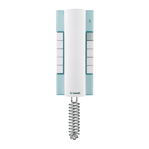
Videocitofono serie Bravo a cablaggio Comelbus
Bravo series door entry monitor for use with the Comelbus digital door entry system
Vidéophone série Bravo à câblage Comelbus
01-2006
FT CB 08
1
2
3
4
5
6
TECHNICAL
SHEET
FOGLIO
TECNICO FEUILLE
TECHNIQUE
GBIF
GROUP S.P.A.
FT CB 08 2
8
1
2
3
4
5
6
412
3
2
1
5
6
7
9
11
10
+
--
13
Descrizione monitor e informazioni utente.
Description of the monitor and user information.
Description du moniteur et informations utilisateur.
I
GB
F
Avvertenze:
• Effettuare l’installazione seguendo scrupolosamente le istruzioni fornite dal costruttore ed in conformità alle norme vigenti.
•Tutti gli apparecchi devono essere destinati esclusivamente all’uso per cui sono stati concepiti. Comelit Group S.p.A. declina ogni responsabilità per un
utilizzo improprio degli apparecchi, per modifiche effettuate da altri a qualunque titolo e scopo, per l’uso di accessori e materiali non originali.
•Tutti i prodotti sono conformi alle prescrizioni delle direttive CEE 73/23-89/336 e ciò è attestato dalla presenza della marcatura CE sugli stessi.
•Evitare di porre i fili di montante in prossimità di cavi di alimentazione (230/400V).
Instructions:
•Install the equipment by carefully following the instructions given by the manufacturer and in compliance with the legislation in force.
•All the equipment must only be used for the purpose it was built for. Comelit Group S.p.A. declines any responsibility for improper use of the apparatus,
for modifications made by others under any title or scope, and for the use of accessories and materials which are not the original ones.
• All the products comply with the requirements of the EEC 73/23-89/336 directives. This is proved by the CE mark on the products.
• Do not run the riser wires in proximity of the power supply cables (230/400V).
Instructions
•Effectuer l’installation en suivant scrupuleusement les instructions fournies par le constructeur et conformément aux normes en vigueur.
• Tous les appareils doivent être strictement destinés à l’emploi pour lequel ils ont été conçus. Comelit Group S.p.A. décline toute responsabilité en cas de
mauvais usage des appareils, pour des modifications effectuées par d’autres personnes pour n’importe quelle raison et pour l’ utilisation d’accessoires non
fournis par nous.
• Tous les produits sont conformes aux prescriptions demandées par les normes CEE 73/23-89/336. Cela est attesté par la présence du marque CE sur les
produits.
• Eviter de placer les fils de montant à proximité des câbles d’alimentation (230/400 V).
I
GB
F
FT CB 08
3FT CB 08
I Monitor Videocitofonici Comelit della serie Bravo Art. 5701 (Monitor in bianco e
nero) e Art. 5702 (Monitor a colori), sono compatibili con i Monitor delle serie
precedenti: Eurocom, Videocom, Diva. La staffa di fissaggio (Art. 5708) completa
il Monitor e determina il sistema di cablaggio Comelbus.
1. Selettore suoneria/servizio Privacy a 3 posizioni:
Posizione sinistra: Suoneria volume massimo.
Posizione centrale: Suoneria volume medio.
Posizione destra : Attivazione funzione Privacy.
(Per servizio Privacy si intende l’esclusione della chiamata dal posto esterno
o centralino; l’attivazione della funzione Privacy è evidenziata dalla comparsa
di un indicatore rosso a lato del selettore).
2. Led di segnalazione (disponibile di serie).
3. Pulsante Apriporta .
4. Pulsante 1 disponibile di serie (riferimento in morsettiera COM CPS).
5. Pulsante 2 disponibile di serie (riferimento in morsettiera C2 P2).
6. Pulsanti opzionali per attivazione funzioni supplementari (1)
7. Pulsanti o Led opzionali per attivazione/visualizzazione funzioni
supplementari (2)
8. Schermo per visualizzazione immagine da posto esterno.
9. Cartoncino intercambiabile e personalizzabile tramite Kit opzionale.
10.
Manopola regolazione luminosità (ruotare in senso orario per aumentare la
luminosità).
11. Gancio di fissaggio.
12. Etichetta memo-pulsanti su cui è possibile riportare la funzione dei pulsanti
del Monitor (da applicare sul Monitor sotto la cornetta come indicato in figura).
L’etichetta adesiva è allegata ai Monitor Art. 5701 e Art. 5702 nel manuale
utente FT BRAVO 01.
13. Cornetta Monitor (Sollevare la cornetta per iniziare la comunicazione).
(1) Pulsanti disponibili con scheda opzionale Art. 5733.
(2) Pulsanti disponibili con scheda opzionale Art. 5733.
Led di visualizzazione disponibili con scheda opzionale Art. 5734.
The Comelit Video door entry Monitors in the Bravo series Art. 5701 (Black and
white Monitor) and Art 5702 (Colour Monitor), are compatible with the Monitors of
the previous series: Eurocom, Videocom and Diva. The fixing bracket (Art. 5708)
completes the Monitor and determines the Comelbus cabling system.
1. 3-position selector for Call tone/Privacy service.
Left-hand position: Call tone at maximum volume.
Central position: Call tone at medium volume.
Right-hand position : Activation of Privacy service.
(Privacy service means exclusion of the call from the external unit or from the
porter switchboard; Activation of the Privacy function is shown by a red
indicator appearing on the left-hand side of the selector).
2. Signalling LED (available as standard).
3. Door-opening pushbutton .
4. Pushbutton 1 available as standard (reference in terminal board COM CPS).
5. Pushbutton 2 available as standard (reference in terminal board P2 C2).
6. Optional pushbuttons to activate additional functions (1)
7. Optional pushbuttons or LEDs to activate/display additional functions (2).
8. Monitor Screen.
9. Masking Templates which can be interchanged and personalised using an
optional Kit.
10. Brightness adjustment knob (turn clockwise to increase brightness).
11. Fixing bracket.
12. Pushbutton memo label where the Monitor pushbutton functions can be
indicated (to be applied to the Monitor under the handset as shown in the
figure). The adhesive label is enclosed with Monitors Art. 5701 and Art. 5702
in the FT BRAVO 01 user manual.
13. Monitor handset (Lift the handset to start communication).
(1) Pushbuttons available with optional card Art. 5733.
(2) Pushbuttons available with optional card Art. 5733.
Display LEDs available with optional card Art. 5734.
Les moniteurs des visiophones Comelit de la série Bravo Art. 5701 (moniteur en
noir et blanc) et Art. 5702 (moniteur couleur) sont compatibles avec les moniteurs
des séries précédentes: Eurocom, Videocom et Diva. La bride de fixation (art.
5708) complète le moniteur et elle détermine le système de câblage Comelbus.
1. Sélecteur sonnerie/service Privacy à 3 positions.
Position à gauche: Sonnerie volume maximum.
Position centrale: Sonnerie volume moyen.
Position à droite : Activation du service Privacy.
(Le Service Privacy exclut l’appel de la plaque de rue ou du Hp-micro;
l’activation de la fonction Privacy est indiquée par l’éclairage d’une led rouge
sur le côté du sélecteur).
2. Led de signalisation (disponible de série).
3. Bouton Ouvre-porte .
4.
Bouton 1 disponible de série (connexion sur le bornier de raccordement COM CPS)
.
5. Bouton 2 disponible de série (bornes de raccordement C2 P2).
6. Boutons en option pour activation fonctions supplémentaires (1)
7. Boutons ou leds en option pour activation/affichage fonctions
supplémentaires (2).
8. Écran de visualisation du moniteur.
9. Carton interchangeable et personnalisable au moyen du kit en option.
10. Bouton de réglage de la luminosité (tourner dans le sens des aiguilles d’une
montre pour augmenter la luminosité).
11. Crochet de fixation.
12. Étiquette mémo-boutons sur laquelle on peut indiquer la fonction des boutons
du Moniteur (à appliquer au moniteur sous le récepteur, de la manière
indiquée dans la figure). L’étiquette autocollante est annexée aux moniteurs
Art. 5701 et Art. 5702 dans le manuel de l’utilisateur FT BRAVO 01.
13. Récepteur Moniteur (Soulever le récepteur pour commencer la
communication).
(1) Boutons disponible avec la carte en option Art. 5733.
(2) Boutons disponible avec la carte en option Art. 5733.
Leds de visualisation disponible avec la carte en option Art. 5734.
GB
IF
GROUP S.P.A.
FT CB 08 4
CV2
CV7
CV1
CV6
CV5
CV3
CV4
145
cm
CV2
CV7
CV1
CV6
CV5
CV3
CV4
1
2
3
4
5
6
10,2 11
14,4
8,1
1,4
1,4
CV2
CV7
CV1
CV6
CV5
CV3
CV4
1
2
3
4
5
6
CV2
CV7
CV1
CV6
CV5
CV3
CV4
1
2
3
4
5
6
1
2
Fig. 1 Fig. 2 Fig. 3
Fig. 4
1
2
3
4
5
6
3
2
1
Fig. 5
5
2
6
1
7
3
4
Fig. 6
FT CB 08
5FT CB 08
Fig. 1 Installazione Staffa Art. 5708 su scatola serie civile 503 (Art. 4517).
Fig. 2 Installazione a muro Staffa Art. 5708 con 4 viti a tassello. Utilizzabile
eventualmente anche con scatola serie civile 503 (Art. 4517) per
migliorare il fissaggio della staffa.
Fig. 3 Misure di ingombro del Monitor in relazione ai punti di fissaggio della
Staffa Art. 5708.
Fig. 4 Procedura di aggancio Monitor.
Fig. 5 Procedura per togliere il Monitor dalla staffa a cui è agganciato.
Fig. 6 1. Connettore Staffa-Monitor.
2. Morsetti di connessione impianto:
AL Morsetto ingresso comando allarme.
AP Morsetto di ingresso comando apriporta.
CAP Morsetto di ingresso chiamata da piano.
OUT1 Morsetto per uscita ausiliaria.
ALE Morsetto contatto allarme esterno.
PAN Morsetto contatto di panico.
CP2 Morsetto di ingresso chiamata a centralino secondario.
LED Morsetto di ingresso Led di segnalazione.
RFP Morsetto comando Relè scambio su chiamata digitale.
CFP Morsetto di ingresso chiamata porta tradizionale.
+24 Morsetto di alimentazione BUS.
LIN Morsetto di ingresso linea BUS.
4- Negativo Fonica.
3Morsetto di uscita microfono Monitor.
2Ingresso altoparlante Monitor.
SUscita ripetizione di chiamata.
+ - Ingresso di alimentazione Monitor positivo (+) e massa (-).
SH/V2 Schermo segnale video coassiale o V2 per segnale video
differenziale.
V/V1 Ingresso segnale video coassiale o V1 per segnale video
differenziale.
CPS COM Contatti NO (24V-100mA max) Pulsante 1 del Monitor.
(Vedi variante a pagina 14)
C2 P2 Contatti NO (24V-100mA max) Pulsante 2 del Monitor.
3. CV2_V1 Ponticello per la chiusura 75 ohm del segnale video, da
tagliare in caso di collegamento in cascata (sia nel caso di Segnale
video coassiale che differenziale).
CV2_V2 Ponticello per la chiusura 75 ohm del segnale video, da
tagliare in caso di collegamento in cascata (solo in caso di Segnale
video differenziale). Vedi variante a pagina 13).
4. CV1 CV3 Ponticelli da tagliare per liberare il Pulsante 1 (contatto NO
24V-100mA max).
5. JP4 - DL1 Jumper e Led di programmazione. In fase di programmazione
il led lampeggia.
6. CV4 Tagliare questo ponticello affinché su chiamata da posto esterno
o centralino, il Monitor suoni ripetutamente per un tempo massimo di
60 secondi se la cornetta non viene sollevata.
7. TM1 Trimmer di regolazione ampiezza segnale video.
Fig. 1 Installation of Bracket Art. 5708 on civil series box 503 (Art. 4517).
Fig. 2 Installation of Bracket Art. 5708 with 4 expansion screws. Can also be used
if necessary with civil series box 503 (Art. 4517) to improve Bracket fixing.
Fig. 3 Overall dimensions of the Monitor in relation to the fixing points of
Bracket Art. 5705.
Fig. 4 Procedure for mounting the Monitor.
Fig. 5 Procedure for removing the Monitor from the bracket it is hooked up to.
Fig. 6 1. Bracket-Monitor connector.
2. System connection terminals:
AL Alarm control input terminal.
AP Door-opening control input terminal.
CAP Local floor calling input terminal.
OUT1 Terminal for auxiliary output.
ALE External alarm contact terminal.
PAN Panic contact terminal.
CP2 Input terminal of call to secondary switchboard.
LED Signalling LED input terminal.
RFP Terminal for control of changeover Relay on digital call.
CFP Traditionalloval door call input terminal.
+24 BUS power supply Terminal.
LIN BUS line input terminal.
4- Sound negative.
3Monitor microphone output terminal.
2Monitor loudspeaker input.
SCall repetition output.
+ - Monitor power supply positive (+) and negative (-) input.
SH/V2 Coaxial screen video signal or V2 for differential video signal.
V/V1 Coaxial video signal input or V1 for differential video signal.
CPS COM NO Contacts (24V-100mA max) Pushbutton 1 of the
Monitor. See variant on page 14).
C2 P2 NO Contacts (24V-100mA max) Pushbutton 2 of the Monitor.
3. CV2_V1 Bridge for 75 ohm closing of the video signal, to be cut in the
case of cascade connection (both in the case of Coaxial and
differential video signal)
CV2_V2 Bridge for 75 ohm closing of the video signal, to be cut in the
case of cascade connection (only in the case of Differential video
signal). See variant on page 13..
4. CV1 CV3 Bridge to be cut to free Pushbutton 1 (NO contact 24V-
100mA max).
5. JP4 - DL1 Jumper and programming LED. During programming the
LED flashes.
6. CV4 Cut this bridge so that, on a call from the external unit or
switchboard, the Monitor rings repeatedly for a maximum time of 60
seconds if the handset is not picked up.
7. TM1 Video signal amplitude adjustment trimmer.
Fig. 1 Installation Bride art. 5708 sur boîtier série civile 503 (Art. 4517)
Fig. 2 Installation en saillie bride art. 5708 avec 4 vis tamponnées.
Éventuellement utilisable avec le boîtier série civile 503 (Art. 4517) pour
améliorer la fixation de la bride.
Fig. 3 Dimensions d’encombrement du moniteur par rapport aux points de
fixation de la bride Art. 5708.
Fig. 4 Procédure de fixation du moniteur.
Fig. 5 Procédure pour déposer le moniteur de la bride à laquelle il est fixé
Fig. 6 1. Connecteur Bride-Moniteur
2. Bornes de connexion installation
AL Borne d’entrée commande alarme
AP Borne d’entrée commande ouvre-porte
CAP Borne d’entrée appel palier
OUT1 Borne pour sortie auxiliaire.
ALE Borne contact alarme extérieure.
PAN Borne contact de panique.
CP2 Borne d’entrée appel au HP-micro secondaire.
LED Borne d’entrée led de signalisation.
RFP Borne de commande relais échange sur appel numérique.
CFP Borne d’entrée appel porte traditionnelle.
+24 Borne d’alimentation BUS.
LIN Borne d’entrée ligne BUS.
4- Négatif Phonie.
3Borne de sortie micro Moniteur.
2Entrée haut-parleur Moniteur.
SSortie répétition d’appel.
+ - Entrée d’alimentation Moniteur positif (+) et masse (-).
SH/V2 Écran signal vidéo coaxial ou V2 pour signal vidéo différentiel.
V/V1 Entrée signal vidéo coaxial ou V1 pour signal vidéo différentiel.
CPS COM Contacts NO (24V-100mA max) Bouton 1 du Moniteur.
Voir variante page 14).
C2 P2 Contacts NO (24V-100mA max) Bouton 2 du Moniteur.
3. CV2_V1 Pont pour la fermeture 75 Ohms du signal vidéo, à couper en
cas de connexion en cascade (aussi bien si le Signal Vidéo est coaxial
que différentiel).
CV2_V2 Pont pour la fermeture 75 Ohms du signal vidéo, à couper en
cas de connexion en cascade (seulement si le Signal Vidéo est
différentiel). Voir variante page 13.
4. CV1 CV3 Pont à couper pour dégager le Bouton 1 (contact NO 24V-
100mA max).
5. JP4 - DL1 Jumper et led de programmation. Durant la programmation
la led clignote.
6. CV4 Couper ce pontet pour que, lors de l’appel de la plaque de rue
ou du HP-micro, le moniteur retentisse à plusieurs reprises pendant
un délai maximum de 60 secondes, si on ne décroche pas le
récepteur.
7. TM1 Trimmer de réglage de l’amplitude du signal vidéo.
Staffa in programmazione Staffa non in programmazione
Bracket in programming mode Bracket not in programming mode
Bride en programmation Bride non en programmation
I
GB
F
GROUP S.P.A.
FT CB 08 6
PROGRAMMING BRACKET ART. 5708
Each Bracket must be programmed by the installer. There are two programming
procedures provided, depending whether the bracket is mounted without a monitor (A) or
already completed with monitor (B).
Step 1-A (to be carried out when just the bracket is mounted).
Move programming jumper JP4.The programming DL1 LED illuminates on bracket Art. 5708.
Step 1-B (to be carried out when the monitor is fitted).
At the same time and continuously, press the Pushbutton and Pushbutton 1 for at
least 5 seconds. The bracket automatically enters the programming mode and gives a
pulsed warning tone (tone for 0.4 sec., 2 second pause). It remains in the programming
mode for 60 seconds.
Step 2 (to be carried out on art. 3350, 3140/6D or 3170).
Insert the jumper between terminals PG and (-).
Follow the specific instructions for each digital module to access the programming
menu.
Step 3 (to be carried out on art. 3350, 3140/6D or 3170).
Enter the number to be assigned to the bracket Then press bell button .
Step 4-A (to be carried out in conjunction with Step 1A)*.
* If programming has been carried out correctly, the LED will flash to confirm the
operation. Put programming jumper JP4 of bracket Art. 5708 back into its initial position.
Step 4-B (to be carried out alternatively to the previous one in conjunction with Step 1-B).
After programming from 3350, 3140/6D or 3170, bracket art. 5708 emits a
confirmation tone and exits the automatic programming mode.
Step 5 (to be carried out on art. 3350, 3140/6D o 3170).
Remove the programming jumper between terminals PG and (-).
N.B.: during programming, articles 5708, 3350, 3140/6D and 3170 insert their own
audio. If you are working on the system, and if the monitor is complete, it is possible to
communicate between the call module and the monitor.
CHANGING MONITOR CALL TONES
Follow the procedure below to change the Monitor call tones:
1Keep the Pushbutton pressed until a confirmation tone is heard (this operation
is only possible with the system in the stand-by situation; otherwise the signalling
LED will flash to warn the user that this is not so).
2Press and release the Pushbutton:
Once: (1 confirmation tone is given) to change the tone of a call from the external unit.
Twice: (2 confirmation tones are given) to change the switchboard call tone.
Three times: (3 confirmation tones are given) to change the local floor call tone.
Any further pressing on the key repeats the sequence described above.
After the last time the Pushbutton is pressed, wait for a confirmation tone before
passing on to the following stage.
3Press and release the Pushbutton to scroll the various tones available in sequence.
If you want to hear the same tone several times, keep the Pushbutton pressed.
4Lift the handset and put it back down to confirm selection of the last bell heard and
to exit (at any time) from the Monitor call tone variation mode. On exiting from the
Monitor a confirmation tone will be given.
PROGRAMMAZIONE STAFFA ART. 5708
Ogni Staffa deve essere codificata dall'installatore. Sono previste due procedure di
programmazione a seconda che la staffa sia montata senza monitor (A) o già completa
del monitor (B).
Passo 1-A (da effettuarsi nel caso di sola staffa montata).
Spostare il jumper di programmazione JP4; si accende il led di programmazione DL1
sulla staffa Art. 5708.
Passo 1-B (da effettuarsi in alternativa al precedente nel caso di staffa già
montata con il monitor).
Premere contemporaneamente e in modo continuo per almeno 5 secondi il Pulsante
Apriporta e il Pulsante 1. La staffa entra in programmazione e genera un tono
impulsato di avviso (0,4 sec. di tono, 2 secondi di pausa). Rimane in programmazione
per 60 secondi.
Passo 2 (da effettuarsi sull’art. 3140/6D, 3170 o 3350).
Inserire il cavallotto fra i morsetti PG e (-).
Seguire le istruzioni specifiche di ogni modulo digitale per accedere al menu di
programmazione.
Passo 3 (da effettuarsi sull’art. 3140/6D, 3170 o 3350).
Digitare il numero che si vuole assegnare alla scheda più il tasto (campana).
Passo 4-A (da effettuarsi in corrispondenza del passo 1A)*.
* Se la programmazione è avvenuta correttamente il Led lampeggerà per confermare
l’operazione. Rimettere nella posizione iniziale il jumper JP4 di programmazione della
staffa Art. 5708.
Passo 4-B (da effettuarsi in alternativa al precedente in corrispondenza del passo 1-B).
Dopo la programmazione dal 3140/6D, 3170 o 3350 la staffa art. 5708 emette un tono
di conferma ed esce dalla programmazione in modo automatico.
Passo 5 (da effettuarsi sull’art. 3140/6D, 3170 o 3350).
Togliere il cavallotto di programmazione fra i morsetti PG e (-).
N.B.: durante la programmazione gli articoli 5708, 3140/6D, 3170 e 3350 inseriscono la
propria fonica. Se si sta lavorando sull’impianto, e se il monitor è completo, è possibile
comunicare tra il porter e il monitor.
VARIAZIONE SUONERIE MONITOR
Seguire la seguente procedura per variare le suonerie del Monitor:
1Tenere premuto il Pulsante fino a che non verrà emesso un suono di conferma
(l’operazione è possibile solo con l’impianto in situazione di riposo; in caso contrario
il led di segnalazione lampeggerà per avvisare l’utente).
2Premere e rilasciare il Pulsante :
1 volta (viene emesso un tono di conferma) per modificare la suoneria di chiamata
da posto esterno.
2 volte (vengono emessi 2 toni di conferma) per modificare la suoneria di chiamata
da centralino.
3 volte (vengono emessi 3 toni di conferma) per modificare la suoneria del
campanello di piano.
Ulteriori pressioni del Pulsante ripetono la sequenza appena descritta.
Dopo l’ultima pressione del Pulsante attendere un suono di conferma selezione
prima di passare alla fase seguente.
3Premere e rilasciare il Pulsante per scorrere in sequenza le varie suonerie
disponibili. Nel caso si voglia riascoltare più volte la stessa suoneria mantenere
premuto il Pulsante .
4Sollevare e riagganciare la cornetta per confermare la scelta dell’ultima suoneria
ascoltata e per uscire (in qualunque momento) dalla modalità di variazione suoneria
Monitor. All’uscita dalla modalità di variazione suoneria Monitor verrà emesso un
suono di conferma.
IGB
FT CB 08
7FT CB 08
PROGRAMMATION BRIDE ART. 5708
Toutes les cartes d’interface doivent être codées par l’installateur. Deux procédures de
programmation sont prévues selon si la bride est montée sans moniteur (A) ou avec le
moniteur (B).
Etape 1-A (à effectuer au cas où seulement la bride serait montée)
Déplacer le jumper de programmation JP4; une led de programmation DL1 s’éclaire sur
la bride Art. 5708.
Etape 1-B (à effectuer dans l’alternative à la précédente au cas où la bride serait
déjà montée avec le moniteur).
Appuyer en même temps et d’une manière continue pendant au moins 5 secondes sur
les touches et le Bouton 1. La bride entre en programmation et elle génère une
tonalité pulsée d’avertissement (0, 4 sec. de tonalité, 2 secondes de pause). Elle
demeure en programmation pendant 60 secondes.
Etape 2 (à effectuer sur l’art. 3350, 3140/6D ou 3170).
Introduire le cavalier entre les bornes PG et (-).
Pour accéder au menu de programmation, suivre les instructions spécifiques pour
chaque module numérique.
Etape 3 (à effectuer sur l’art. 3350, 3140/6D ou 3170).
Taper le numéro que l’on désire attribuer à la bride + touche (cloche).
Etape 4 (à effectuer en correspondance de l’étape 1A)*.
*
Si la programmation a eu lieu correctement, la led clignotera pour confirmer l’opération.
Replacer dans sa position initiale le jumper JP4 de programmation de la bride Art. 5708.
Etape 4-B (à effectuer en alternative à la précédente en correspondance de l’étape 1-B).
Après la programmation du 3350, 3140/6D ou du 3170, la bride art. 5708 émet une
totalité de confirmation et elle quitte la programmation en mode automatique.
Etape 5 (à effectuer sur l’art. 3350, 3140/6D ou 3170).
Retirer le cavalier de programmation entre les bornes PG et (-).
N.B. : Durant la programmation les articles 5708, 3350, 3140/6D et 3170 permettent de
maintenir la phonie. Si vous êtes en train de travailler sur l’installation et si le moniteur
est complet, la communication entre la "porte" et le moniteur est possible.
PROGRAMMATION SONNERIES MONITEUR
Pour varier la sonnerie du moniteur, suivre la procédure ci-dessous:
1Maintenir appuyé le Bouton jusqu’à ce qu’une tonalité de confirmation soit
audible (cette opération n’est possible que lorsque le système est en condition de
repos; dans le cas contraire, la led de signalisation clignote pour avertir l’utilisateur).
2Appuyer et relâcher le Bouton :
1 fois (émission d’une tonalité de confirmation) pour modifier la sonnerie d’appel de
la plaque de rue.
2 fois (émission de 2 tonalités de confirmation) pour modifier la sonnerie du Hp-micro.
3 fois (émission de 3 tonalités de confirmation) pour modifier la sonnerie de l’appel palier.
Appuyer ultérieurement sur la Bouton pour répéter en séquence les opérations
décrites ci-dessus.
Après le dernier appui sur le Bouton , attendre la tonalité de confirmation de la
sélection avant de passer à l’étape suivante.
3Appuyer sur le Bouton et le relâcher pour faire défiler en séquence les
différentes sonneries disponibles. Si vous désirez écouter plusieurs fois la même
sonnerie, maintenir appuyé le Bouton .
4Décrocher le récepteur et le raccrocher pour confirmer le choix de la sonnerie choisie.
Une tonalité de confirmation vous avertira que vous avez quitté le mode de
programmation de la sonnerie Moniteur.
F
GROUP S.P.A.
FT CB 08 8
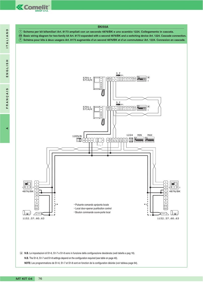
CBV/01BC
Impianto base con un ingresso Audio/Video digitale.
Basic system with one digital Audio/Video entrance.
Installation de base avec une entrée Audio/Vidéo numérique.
I
GB
F
Vedi variante CB/BB
See variant CB/BB
Voir variante CB/BB
FT CB 08
9FT CB 08
CBV/01BC/A
Impianto base con un ingresso Audio/Video digitale (segnale video differenziale).
Basic system with one digital Audio/Video entrance (differential video signal).
Installation de base avec une entrée Audio/Vidéo numérique (signal vidéo différentiel).
I
GB
F
Vedi variante CB/BB
See variant CB/BB
Voir variante CB/BB
GROUP S.P.A.
FT CB 08 10
Impianto 2 ingressi Audio/Video digitali.
System with 2 digital Audio/Video entrances.
Installation 2 entrées Audio/Vidéo numériques.
CBV/EN/184BC
I
GB
F
FT CB 08
11 FT CB 08
Vedi variante CB/BB
See variant CB/BB
Voir variante CB/BB
GROUP S.P.A.
FT CB 08 12
Collegamento in cascata segnale video coassiale.
Connection in cascade of coaxial video signal.
Connexion en cascade du signal vidéo coaxial.
CB/BD
I
GB
F
Collegamento in cascata segnale video differenziale.
Connection in cascade of differential video signal.
Connexion en cascade du signal vidéo différentiel.
I
GB
F
Vedi variante CB/BB
See variant CB/BB
Voir variante CB/BB
Vedi variante CB/BB
See variant CB/BB
Voir variante CB/BB
FT CB 08
13 FT CB 08
CB/BA
Collegamento monitor per impianti Comelbus in configurazione completa. Utilizzo ingresso CAP per chiamata fuoriporta (da piano).
Utilizzo ingresso comando led di segnalazione per usi vari.
Connection of monitor for Comelbus systems in the complete configuration. Use of CAP entrance for floor door call (from floor).
Application for various uses of Led.
Connexion moniteur pour installation Comelbus en configuration complète. Utilisation entrée CAP pour appel du palier.
Utilisation pour usages divers du Led.
I
GB
F
Utilizzo per usi vari del pulsante 1.
Use of various uses of pushbutton 1.
Utilisation pour usages divers du bouton 1.
CB/BB
I
GB
F
GROUP S.P.A.
FT CB 08 14
NOTE - NOTES - NOTE
FT CB 08
15 FT CB 08
NOTE - NOTES - NOTE
Comelit Group S.p.A. - Via Don Arrigoni 5 - 24020 Rovetta S. Lorenzo BG Italy - tel. (+39) 0346 750 011 - fax (+39) 0346 71436
www.comelit.it [email protected] [email protected] export.depar[email protected]
15, Rue Jean Zay
69800 Saint Priest
Tel 04 72 28 06 56
Fax 04 72 28 83 29
http://www.comelit.fr
E-mail: [email protected]
CERTIFICAZIONE DEI SISTEMI
QUALITA' DELLE AZIENDE
UNI EN - ISO 9001:2000
F
Aventurijn 220
3316LB Dordrecht
Tel 078 65 11 201
Fax: 078 61 70 955
http://www.comelit.nl
E-mail: [email protected]
NL
Chaussée de Ninove, 900
1703 Schepdaal (Dilbeek)
Ninoofsesteenweg, 900
1703 Schepdaal (Dilbeek)
Tel 02 411 50 99 - Fax 02 411 50 97
http://www.comelit.be
E-mail: [email protected]
B
1 Brownfields
Welwyn Garden City
HERTS - AL7 1AN
Tel 01707 377203
Fax 01707 377204
http://www.comelitgroup.co.uk
E-mail: [email protected]
UK SG
SINGAPORE
REPRESENTATIVE OFFICE
53 Meyer Road - Meyer Tower #19-00
Singapore 437878
Tel:+65-6440 5857
Fax: +65 6440 5136
E-mail: [email protected]
Josef Estivill 67/69
08027 Barcelona
Tel. 932 430 376
Fax 934 084 683
http://www.comelit.es
E-mail: [email protected]
E
FT/CB/08 – 1aedizione 01/2006 – cod. 22590283

Other manuals for Bravo Series

2

This manual suits for next models

1

Other Comelit Intercom System manuals

Comelit HFX-7004M User manual

Comelit

Comelit HFX-7004M User manual

Comelit Mini 6701 User manual

Comelit

Comelit Mini 6701 User manual

Comelit FT VCC 04 Instruction Manual

Comelit

Comelit FT VCC 04 Instruction Manual

Comelit HFX-700B User manual

Comelit

Comelit HFX-700B User manual

Comelit 8171IP User manual

Comelit

Comelit 8171IP User manual

Comelit 3311 User manual

Comelit

Comelit 3311 User manual

Comelit Mini 6721W User manual

Comelit

Comelit Mini 6721W User manual

Comelit 1440A User manual

Comelit

Comelit 1440A User manual

Comelit Mini 6721W User manual

Comelit

Comelit Mini 6721W User manual

Comelit 6602W User manual

Comelit

Comelit 6602W User manual

Comelit UT1010B User manual

Comelit

Comelit UT1010B User manual

Comelit UT2020 User manual

Comelit

Comelit UT2020 User manual

Comelit 2602U User manual

Comelit

Comelit 2602U User manual

Comelit 1414 User manual

Comelit

Comelit 1414 User manual

Comelit 6741W User manual

Comelit

Comelit 6741W User manual

Comelit 8171I User manual

Comelit

Comelit 8171I User manual

Comelit 6101Z User manual

Comelit

Comelit 6101Z User manual

Comelit People PL6721 User manual

Comelit

Comelit People PL6721 User manual

Comelit Visto ViP WiFi User manual

Comelit

Comelit Visto ViP WiFi User manual

Comelit KAE5061 Owner's manual

Comelit

Comelit KAE5061 Owner's manual

Comelit HFX-9500M User manual

Comelit

Comelit HFX-9500M User manual

Comelit 1998NV User manual

Comelit

Comelit 1998NV User manual

Comelit 4879KC User manual

Comelit

Comelit 4879KC User manual

Comelit UT1020VC Owner's manual

Comelit

Comelit UT1020VC Owner's manual

Popular Intercom System manuals by other brands

WRT Elite Series manual

WRT

WRT Elite Series manual

Amroad ID5101 user guide

Amroad

Amroad ID5101 user guide

ButterflyMX Key Locker installation guide

ButterflyMX

ButterflyMX Key Locker installation guide

urmet domus VOG 7 1760 Quick user guide

urmet domus

urmet domus VOG 7 1760 Quick user guide

CAME 001DC02ENIGMA installation manual

CAME

CAME 001DC02ENIGMA installation manual

Commax AP-3SG user manual

Commax

Commax AP-3SG user manual

Panasonic VL-GM001 Installation and operation guide

Panasonic

Panasonic VL-GM001 Installation and operation guide

Vimar ELVOX 8000 Series Installer's guide

Vimar

Vimar ELVOX 8000 Series Installer's guide

golmar Nexa 90 instruction manual

golmar

golmar Nexa 90 instruction manual

Velleman CAMSET33 manual

Velleman

Velleman CAMSET33 manual

Nywint DK4711 quick guide

Nywint

Nywint DK4711 quick guide

GEV CVB 88320 manual

GEV

GEV CVB 88320 manual

Dahua VTH2611L-WP user manual

Dahua

Dahua VTH2611L-WP user manual

Fanvil i10 Quick installation guide

Fanvil

Fanvil i10 Quick installation guide

PS Engineering PMA7000B Series System installation and operation manual

PS Engineering

PS Engineering PMA7000B Series System installation and operation manual

Grandstream Networks GDS370 Series user manual

Grandstream Networks

Grandstream Networks GDS370 Series user manual

hager REA1 X Series user guide

hager

hager REA1 X Series user guide

Aiphone TCS-MH instructions

Aiphone

Aiphone TCS-MH instructions

manuals.online logo
manuals.online logoBrands
  • About & Mission
  • Contact us
  • Privacy Policy
  • Terms and Conditions

Copyright 2025 Manuals.Online. All Rights Reserved.