manuals.online logo
Brands
  1. Home
  2. •
  3. Brands
  4. •
  5. HRS
  6. •
  7. Cables And Connectors
  8. •
  9. HRS BNC75 Series Manual

HRS BNC75 Series Manual

2022.01
RF-21038
The specification and contents are subject to change without notice. Please check the latest document.
Mounting / Soldering procedure
for BNC 12G connectors
Hirose electric RF engineering team
RF-21038
Jan./2022
Products :BNC(75)-PLR-PC(D)-12G-3
CL302-0088-0-00
2022.01
RF-21038
The specification and contents are subject to change without notice. Please check the latest document. 2
Mounting and soldering procedure
Positioning to a chassis and a PCB
※Before soldering, a connector should be properly positioned to its chassis and
PCB in order not to make any stress on the soldering area after soldering.
Order 1. Positioning ⇒2. Outer contact soldering ⇒3. Center contact soldering
A M2(mm) screw can be used for the
temporally fixing. No need to use this
screw depending on your situation.
No gap between a connector
and a PCB
1. Connector positioning for PCB ※Fluxing
Note
Far excessive amount of
flux left at the designated
area on the picture could
affect its high frequency
performance.
Fluxing area: 4 Soldering areas of outer contacts and a
soldering area of a center contact.
NOTE: A soldered connector must be used after cooled to the operating temperature.
2022.01
RF-21038
The specification and contents are subject to change without notice. Please check the latest document. 3
2. Outer contact soldering
Heat both a PCB pad and a connector contact
so that pour solder into a through hole properly.
GOOD A through
hole(TH) is
fulfilled with
solder. Defect
Lack of
solder
- Wave soldering condition
Preheat : max 100C / max 120sec
Solder : max 245C/ max 5sec
- Hand soldering condition
Preheat : max 100C / max 120sec
Solder iron : max 380C/ max 5sec
Note : reflow soldering can’t be
applied for this connector because of
outer shell swellings.
3. Center contact soldering
Around Dia0.3mm solder suits for center contact soldering.
Excessive soldering criteria
Solder should be in the pad area. Far
excessive solder could cause RF
performance.
Soldering at
bottom area
Soldering Criteria
Mounting and soldering procedure
Order 1. Positioning ⇒2. Outer contact soldering ⇒3. Center contact soldering
NOTE: A soldered connector must be used after cooled to the operating temperature.
Solder should be under the soldering
area. Far excessive solder could cause
RF performance.

This manual suits for next models

2

Other HRS Cables And Connectors manuals

HRS HELIX User manual

HRS

HRS HELIX User manual

HRS GT36A User manual

HRS

HRS GT36A User manual

HRS SignalBee DF13 Series User manual

HRS

HRS SignalBee DF13 Series User manual

HRS DF51-6EP-2C User manual

HRS

HRS DF51-6EP-2C User manual

HRS FH67 Series User manual

HRS

HRS FH67 Series User manual

HRS ZE05 Series User manual

HRS

HRS ZE05 Series User manual

HRS DF51 Series User manual

HRS

HRS DF51 Series User manual

HRS DF57 Series User manual

HRS

HRS DF57 Series User manual

HRS DF63 Series User manual

HRS

HRS DF63 Series User manual

HRS DF57H S-1.2C Series User manual

HRS

HRS DF57H S-1.2C Series User manual

HRS BM25 Series User manual

HRS

HRS BM25 Series User manual

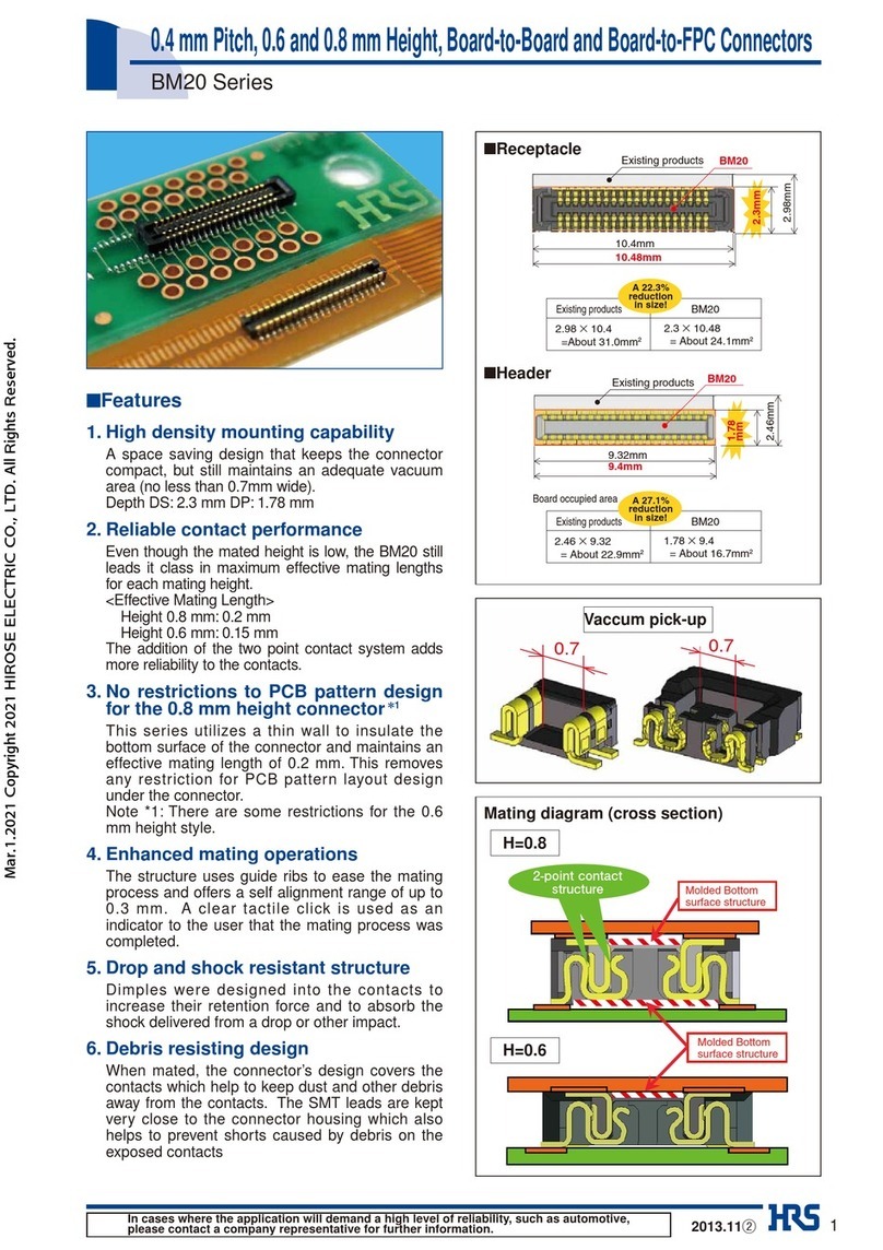
HRS BM20 Series User manual

HRS

HRS BM20 Series User manual

HRS Hirose IT3 Quick start guide

HRS

HRS Hirose IT3 Quick start guide

HRS DF62W Series User manual

HRS

HRS DF62W Series User manual

HRS GT50 Series User manual

HRS

HRS GT50 Series User manual

HRS FH12 Series User manual

HRS

HRS FH12 Series User manual

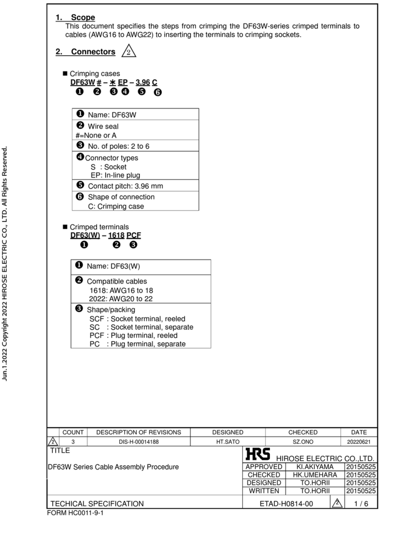
HRS DF63W Series Manual

HRS

HRS DF63W Series Manual

HRS FH29 Series User manual

HRS

HRS FH29 Series User manual

HRS EM30MSD Series User manual

HRS

HRS EM30MSD Series User manual
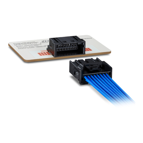
HRS DF62W EP 2.2C Series User manual

HRS

HRS DF62W EP 2.2C Series User manual

HRS ZH05 Series User manual

HRS

HRS ZH05 Series User manual

HRS GT36 User manual

HRS

HRS GT36 User manual

HRS DF40 Series User manual

HRS

HRS DF40 Series User manual

HRS HIF Series User manual

HRS

HRS HIF Series User manual
Popular Cables And Connectors manuals by other brands

LEGRAND 025626 manual

LEGRAND

LEGRAND 025626 manual

topmet OMNI10 AC2 quick start guide

topmet

topmet OMNI10 AC2 quick start guide

FONESTAR FO-552 quick start guide

FONESTAR

FONESTAR FO-552 quick start guide

Kramer 612T installation instructions

Kramer

Kramer 612T installation instructions

Philips SWV3442 Specifications

Philips

Philips SWV3442 Specifications

Allen-Bradley 2711-NC21 Installation instructions manual

Allen-Bradley

Allen-Bradley 2711-NC21 Installation instructions manual

Philips SWA2728W Specifications

Philips

Philips SWA2728W Specifications

ATEN VS0108HA user manual

ATEN

ATEN VS0108HA user manual

Multiplex ChannelPlus C-BCK installation manual

Multiplex

Multiplex ChannelPlus C-BCK installation manual

Allen-Bradley 1585BP installation instructions

Allen-Bradley

Allen-Bradley 1585BP installation instructions

Davis Instruments Car/Boat/RV Lighter Cord instruction manual

Davis Instruments

Davis Instruments Car/Boat/RV Lighter Cord instruction manual

Atlona AT-HDMI-210 Specifications

Atlona

Atlona AT-HDMI-210 Specifications

STODIA 22103322 operating manual

STODIA

STODIA 22103322 operating manual

Anslut 417-049 operating instructions

Anslut

Anslut 417-049 operating instructions

Panduit PCPA13R20 Series installation instructions

Panduit

Panduit PCPA13R20 Series installation instructions

KSH International WPC-832-Con user manual

KSH International

KSH International WPC-832-Con user manual

Sony XA-C40 operating instructions

Sony

Sony XA-C40 operating instructions

Philips SWV3555 Specifications

Philips

Philips SWV3555 Specifications

manuals.online logo
manuals.online logoBrands
  • About & Mission
  • Contact us
  • Privacy Policy
  • Terms and Conditions

Copyright 2025 Manuals.Online. All Rights Reserved.