User manual
OPTICAL LEVEL
CONDTROL Spektra 38
User manual
OPTICAL LEVEL
CONDTROL Spektra 38
User manual
OPTICAL LEVEL
CONDTROL Spektra 38
User manual
OPTICAL LEVEL
CONDTROL Spektra 38
User manual
OPTICAL LEVEL
CONDTROL Spektra 38
User manual
OPTICAL LEVEL
CONDTROL Spektra 38
User manual
OPTICAL LEVEL
CONDTROL Spektra 38
DELIVERY PACKAGE
1. Opcallevel–1pc.
2. 2-mmhexwrench-1pc.
3. Adjusngpin-1pc.
4. Plumb–1pc.
5. Usermanual–1pc.
6. Hardcase–1pc.
OPERATION
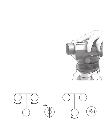
1. Instrument set-up and leveling
a) Set desired height of the tripod
and place it on the ground. Use the
aachment screw to ghtly x the
opcallevelonthetripod(Figure2).
b) Rotate the liing screws A, B, C to
install the bubble vial in the center.
By rotang the A and B screws
simultaneously,movethebubbletothe
right.RotaonofthescrewCwillmove
thebubbleback(Figure3).
CongratulaonsonyourpurchaseofopcallevelSpektra38CONDTROL.
Safetyinstruconsprovidedinthisusermanualshouldbecarefullyread
beforeyouusetheproductfortherstme.
SAFETY REGULATIONS
Aenon! Thisusermanualisanessenalpartofthisproduct.
Theusermanualshouldbereadcarefullybeforeyouusetheproductfor
therstme.Iftheproductisgiventosomeonefortemporaryuse,besure
toencloseusermanualtoit.
-Donotmisusetheproduct.
- It is prohibited to disassemble or repair the product yourself. Entrust
productrepairtoqualiedpersonnelanduseoriginalsparepartsonly.
-Storetheproductbeyondreachofchildrenandunauthorizedpeople.
- Do not use the product in explosive environment, close to ammable
materials.
FUNCTIONS/APPLICATIONS
OpcallevelSpektra38CONDTROLisaprofessionalmeasuringinstrument.
Itisequippedwithacompensatorwithamagnecdampingsystemwith
workingrange±15‘.Itallowstomakehigh-precisionmeasurementsquickly
andcorrectly.
Opcal level Spektra 38 has a 38X magnicaon telescope with coated
opcs,whichsignicantlyimprovesvisibilityandmakesaimingtoremote
objectseasier.Ithasahorizontallimbwith1°graduaonmarksandliing
screws,aswellasanopcalsightonthetelescopeforconvenienttarget
search.
PRODUCT DESCRIPTION
A
C
B A
C
B
2. Aiming and focusing
a)Grid:
Point the telescope on a bright surface or leveling sta,
using the sight. Rotate the eyepiece unl you achieve a
clearandbrightimageofthegrid.
b)Aiming:
Rotate the focusing screw forward to focus on the sta
standing at longer distance or back to focus on the sta
standingatcloserdistanceunlaclearimageappearson
the screen.Rotate the horizontal drive screw to posion
theimageofthestaatthecenteroftheeldofview.
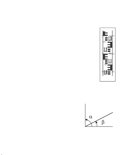
3. Measurements
a)Exceedence:
Aerpoinngonthestatakethereadingsofthemiddle
line,asshownonFigure4.(thereadingis1.195m).
b)Distance:
Take the readings of the upper and boom stadia lines.
Distancebetweentheinstrumentandthestawillbethe
following:
(Reading of the upper line – reading of the boom line) х100,
AsshownontheFigure4:
(1.352m-1.038m)х100=31.4m
с)Angle:
Point the vercal line of the grid to the
targetAandtaketheanglereadingαonthe
limb.PointtothetargetBandtaketheangle
readingβonthelimb.TheanglebetweenA
andBwillbe-α-β(Figure5).
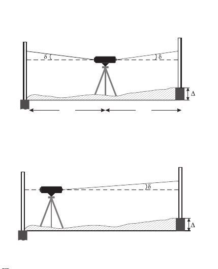
ACCURACY CHECK AND ADJUSTMENT
Despite the fact that all opticallevels with compensator are adjusted
atthefactory,itisnecessarytocarryoutaccuracycheckbeforeuse.
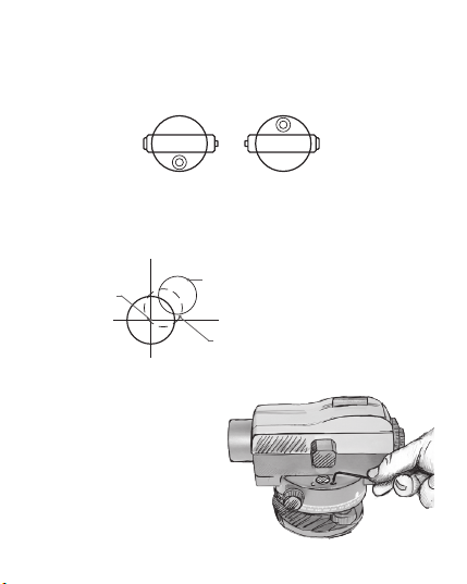
1. Checking the circular bubble vial
a) Adjust the lifting screws to center the bubble vial and rotate the
telescopeby180°.Thebubblevialshouldremaininthecenter(Figure6).
b) If the bubble vial is not in the center, it is necessary to perform
adjustment.
c)Rotatetheliftingscrewstomovethebubblevialhalfwaytothecenter
(Figure7).
d) Turn 2 adjusting screws to
adjustthepositionofthebubble
vial(Figure7).
e)RepeatstepsfromAtoDuntil
the bubble vial doesn’t deviate
fromthecenter(Figure8).
1.Objecvelens
2.Circularvialmirror
3.Eyepiececover
4.Eyepiece
5.Circularbubblevial
6.Horizontalcircle
7.Adjusngscrewsofcircularbubblevial
8.Liingscrews
9.Tripodmount5/8“(ontherearside)
10.Horizontaldrivescrews
11.Focusingscrew
12.Base
TECHNICAL SPECIFICATIONS
Standarddeviationfor1km
doubleline 1 mm
Image Erect
Magnification 38X
Objectiveaperture 38mm
Fieldofview 1°20´
Minimalviewingdistance 0,3m
StadiaRatio 100
LevelvialSensitivity 8'/2mm
HorizontalCircleGraduation 1°
Typeofcompensator magnetic
Range 15'
SettingAccuracy 0,5"
Protectionrate IP54
Dimensions 230x140x170mm
Weight 1.5kg
Thread 5/8"
Figure2
Figure3
Figure4
A
B0
Figure5
Figure6
Figure7
Figure8
1
2
3
4
5
76
8
9
10
11
8
Center
Deviation of the bubble vial
Move the bubble vial to position
marked by dashed line
(half of deviation)