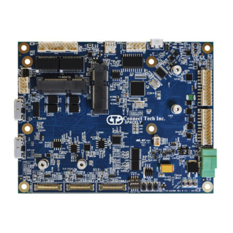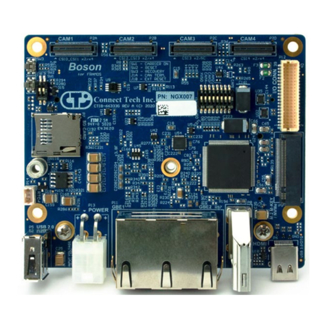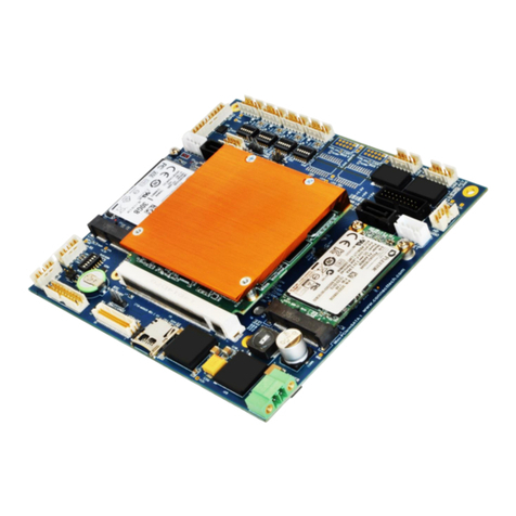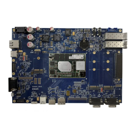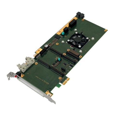
Rogue-X – NVIDIA® Jetson AGX Xavier™ Carrier
Users Guide
Document: CTIM-00082
Revision: 0.01
Page 2 of 40 Date: 2021-04-14
TABLE OF CONTENTS
Table of Contents .......................................................................................................................2
Preface.......................................................................................................................................4
Disclaimer ........................................................................................................................................ 4
Customer Support Overview ........................................................................................................... 4
Contact Information......................................................................................................................... 4
Limited Product Warranty ............................................................................................................... 5
Copyright Notice .............................................................................................................................. 5
Trademark Acknowledgment........................................................................................................... 5
ESD Warning .................................................................................................................................... 6
Revision History .........................................................................................................................6
Introduction...............................................................................................................................7
Product Features and Specifications ............................................................................................... 8
Part Numbers / Ordering Information ............................................................................................. 9
Product Overview.....................................................................................................................10
Block Diagram ................................................................................................................................10
Board (Top Side)............................................................................................................................. 11
Board (Back Side) ...........................................................................................................................12
Connector Summary & Locations ..................................................................................................13
Jumper Summary & Locations .......................................................................................................13
LED Summary .................................................................................................................................14
Detailed Feature Description ....................................................................................................15
LED Locations .................................................................................................................................15
Connector and Switch Locations - Module Side ............................................................................ 16
Jetson AGX Xavier™ Board-to-Board Carrier Connector......................................................17
M.2 M-Key – NVMe..............................................................................................................17
Fan Connector (5V) ..............................................................................................................18
CAN Bus TERM enable switch ..............................................................................................18
Ximea xiX Camera Connector (2 sites) .................................................................................19
Ximea IO Header .................................................................................................................. 21
Connector and Switch Locations – User Interface Side ................................................................. 22
USB UART Debug console – Micro USB-AB ..........................................................................23
USB 3.1/OTG Type C............................................................................................................. 23
USB 3.1 Type C ..................................................................................................................... 24
RTC Battery...........................................................................................................................24
MISC I/O Connector ............................................................................................................. 25
CAN Bus Connector .............................................................................................................. 26
CAMERA Expansion Connector ............................................................................................26
M.2 E-Key – WiFi and Bluetooth Expansion port .................................................................29
Fan Connector (12V) ............................................................................................................ 29
