§
)R CONTENTS
1fffl
iJlEJJJ
INSTRUCTION MANUAL
L
lYL~fm:fr-
BRIEF INTRODUCTION OF THE MACHINE
·························································1
2,
±~ti#;r~~
MAIN TECHNOLOGY SPECIFICATION
·········
······--·······
...............
······
······
······
1
3,
3Z*183:ffl:
INSTALLATION OF THE OIL TRAY
·····································································1
4,
3Z*tJL~
INSTALLATION OF THE HEAD
..............................
···
···
··················
···
···
...............
2
5,
3Z*ll*t~9&.it
INSTALLATION OF KNEE CONTROL DEVICE
·······················
.........................
2
6,
i)ff]~fl*t~*jt
ADJUST KNEE CONTROL DEVICE
....................................
················
...........
3
7,
LUBRICATION
······························
........................................................................
3
8,
i~$
RUN-IN OPERATION
···
······
······
·····················
······
······
···
···············
············
···
············4
9,
INSTALLATION OF THE NEEDLE
···
··················
······
......
············
······
···
··················5
SETTING THE BOBBIN CASE···
......
···················································
············5
_,,,-,,_
O'X
,~,~~-
WINDING THE BOBBIN THREAD
...............................................................
···5
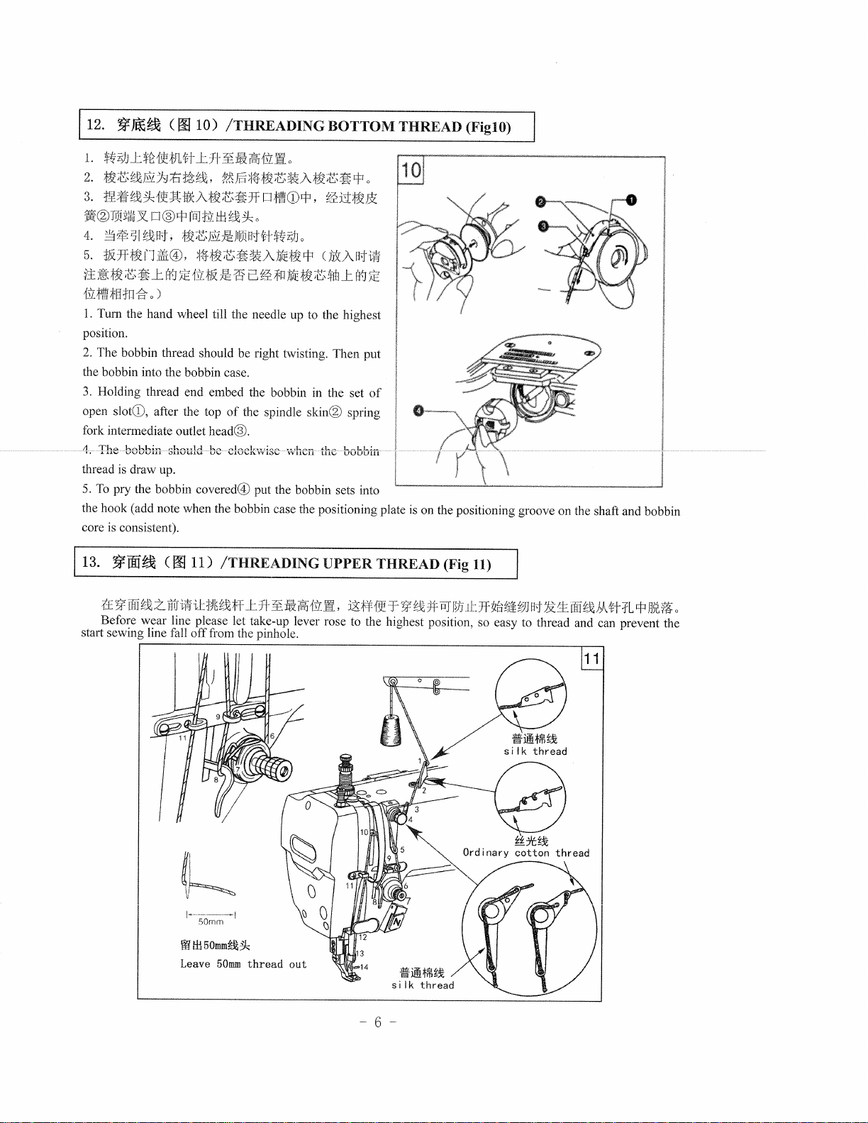
BOTTOM THREAD
·····················
••,•
······
······
···
···
···
···
···
············
······
···
···
···
······
···
···6
UPPER THREAD
··················································································
..............
6
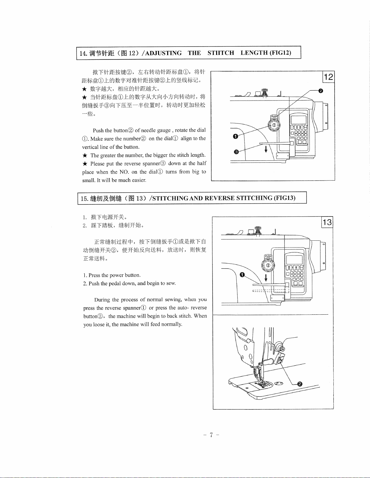
ADJUSTING THE STITCH LENGTH
··································································7
STITCHING AND REVERSE STITCHING
.........................................................
7
ADJUSTING THE THRESD TENSION
··········
..
···························
.....................
g
ADJUSTING THE PRESSURE OF THE PRESSER FOOT
··········
..........................
8
ADJUSTING THE LENGTH OF THE THREAD END
···················
...........
9
ADJUSTING THE TAKE-UP SPRING
............
············
···························
······
······9
ADJUSTING THE PRESSER FOOT HEIGHT
········
........................................
10
ADJUSTING THE PRESSER FOOT HEIGHT ···························...··········
.....
······
10
ADJUSTING THE DOG FEED HEIGHT
······
···
······
············
······
······
···
···
·········
10
ADJUSTING THE DOG FEED ANGLE ················..························
···
······
11
ADJUSTING THE STITCH AND REVERSE STITCH LENGTH ERROR
......
11
25,
t)ff]·tj·fi~t!'ii!H"J1Mt!
ADJUSTING THE LOOSEN THREAD DEVICE OF THE TENSION DISCS
······11
26,
ADJUSTING SYNCHRONIZATION OF THE NEEDLE AND FEED DOG
DEVICE···
12
::1;e;t;,;;·tts,,,r1
1
-1g.
HOOK LUBRICATON ADJUSTMENT
············
...............
···
·········
······
············
···
12
ADJUSTING SYNCHRONIZATION OF THE NEEDLE BAR HEIGHT AND
HOOK···l3
29,
ADJUSTING THE OIL PUMP LUBRICATION
................................................
13
30,
_t;ziHMJ;J8{]t)ff]+~·
ADJUSTING THE TOP-FEEDING MACHNISM
····························
...........
14
3L
13iMt[ljtx_f!:frtfLfz;JH"J'i)fi]1"j-
ADJUSTING WALKING FOOT AND PRESSURE FOOT
···············
......
14
32,
tiB:]t!],
1j\[Js]i;J],\'~HU+:l:8{]1)fi]ff
ADJUSTING THE LIFTING AMOUT OF THE FOOT
...............
15
1N::fs]t[]ltfrJ§}Tfwli'sJlt~B{]i)ff]ff
ADJUSTING THE CLEARANCE BETWEEN THE FOOT
······15
ADJUSTING THE THREAD TRIMMER DEVICE
·······················
.............
16~17
CLEANING
...............
············
······
···············
······
············
······
···
······
························
l8
From the library of Superior Sewing Machine & Supply LLC - www.supsew.com


 User manual")