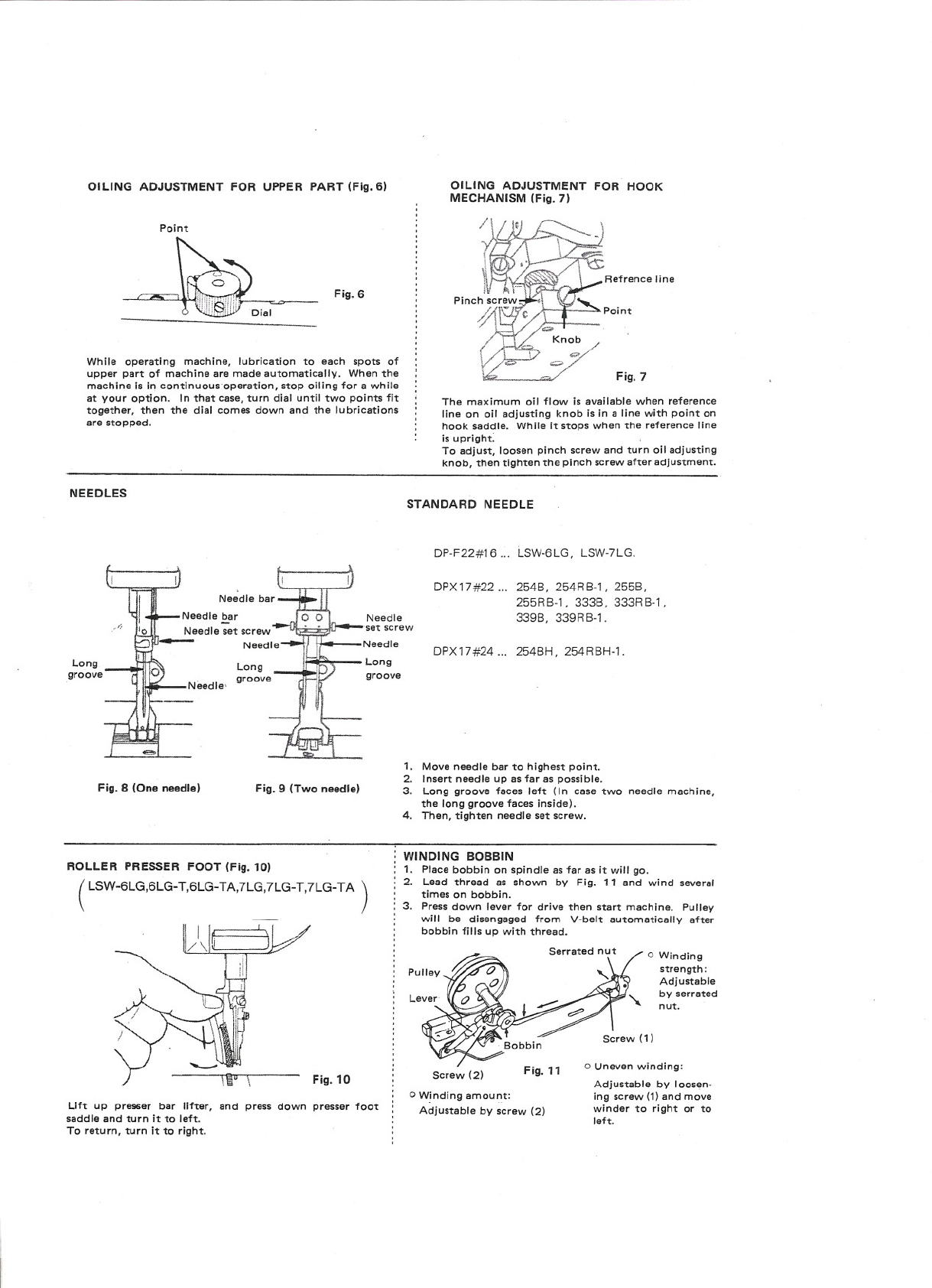
OILING ADJUSTMENT FOR UPPER PART (Fig. 6)
Point
Fig. 6
While operating machine, lubrication to each spots of
upper part of machine are made automatically. When the
machine Is In continuous. operation, stop oiling for a while
at your option. In that case, turn dial until two points fit
together, then the dial comes down and the lubrications
are stopped.
OILING ADJUSTMENT FOR HOOK
MECHANISM (Fig. 7)
Refrence line
Fig. 7
The maximum 011flow is available when reference
line on 011adjusting knob Is In a line with point on
hook saddle. While It stops when the reference line
is upright: .
To adjust, loosen pinch screw and turn 011adjusting
knob, then tighten the pinch screw after adjustment.
NEEDLES STANDARD NEEDLE
Long
groove
Fig. 8 (One needle) Fig. 9 (Two needle)
Needle
set screw
Needle
Long
groove
DP-F22#16... LSW-6LG, LSW-7LG.
DPX17#22... 254B, 254RB-l, 255B,
255RB-l, 333B, 333RB-l,
339B, 339RB-1.
DPX17#24... 254BH, 254RBH-1.
1. Move needle bar to highest point.
2. Insert needle up as far as possible.
3. Long groove faces left (In case two needle machine,
the long groova faces Inside).
4. Then, tighten needle sat screw.
ROLLER PRESSER FOOT (Fig. 10)
(LSW-6LG,6LG-T.6LG-TA.7LG,7LG-T,7LG-TA )
Fig. 10
Lift up prll96ar bar lifter, and press down presser foot
saddle and turn It to left.
To return, turn It to right.
WINDING BOBBIN
1. Place bobbin on spindle as far as It will go.
2. Laad thraad as shown by Fig. 11 and wind several
times on bobbin.
3. Press down lever for drive then start machine. Pulley
will be dlsangaged from V-belt automatically after
bobbin fills up with thread.
o Winding
strangth:
Adjustable
by serrated
nut.
Screw (2) Fig. 11 o Uneven winding:
Adjustable by loosen-
ing screw (1) and move
winder to right or to
left.
o W!ndlng amount:
Adjustable by scraw (2)


 User manual")


