manuals.online logo
Brands
  1. Home
  2. •
  3. Brands
  4. •
  5. novotechnik
  6. •
  7. Transducer
  8. •
  9. novotechnik TMI Series User manual

novotechnik TMI Series User manual

TMI Gebrauchsanleitung
TMI Manual
1General description 2
2Safety instructions 2
2.1 Intended conditions of use 2
2.2 Installation & startup 2
2.3 Check connections 2
2.4 Turning on the system 2
2.5 Check measured values 2
2.6 Check functionality 2
2.7 Failure malfunction 2
3Electrical data 3
4Instruction for installation 3
5 Wiring 3
6Mounting and installation 4
6.1 Flange 4
6.1.2 Thread M18x1,5 5
6.1.3 Thread 3/4"-16UNF 6
6.2 Position marker 7
7Electrical connection 8
7.1 Code 101/103 8
7.2 Code 102 8
7.3 Code 201/203/205 8
7.4 Pin configuration 9
8Output signals 10
8.1 Pulse interface 10
8.2 SSI interface 10
8.3 DyMoS interface 10
8.4 Analog output 11
8.5 Analog dual output option 11
9Special connectors on request 12
9.1 Code 103 12
9.2 Code 111 12
10 Teach-In function 13
11 Required accessories 14
12 Optional accessories 14
13 Ordering code 14
1Allgemeine Beschreibung 2
2Sicherheitshinweise 2
2.1 Bestimmungsgemäße Verwendung 2
2.2 Installation & Inbetriebnahme 2
2.3 Anschlüsse prüfen 2
2.4 Einschalten des Systems 2
2.5 Messwerte prüfen 2
2.6 Funktionsfähigkeit prüfen 2
2.7 Funktionsstörung 2
3Elektrische Daten 3
4Montagehinweis 3
5Anschlüsse 3
6Einbau und Installation 4
6.1 Flansch 4
6.1.2 Gewinde M18x1,5 5
6.1.3 Gewinde 3/4"-16UNF 6
6.2 Positionsgeber 7
7Elektrischer Anschluss 8
7.1 Code 101/103 8
7.2 Code 102 8
7.3 Code 201/203/205 8
7.4 Steckerbelegung 9
8Ausgangssignale 10
8.1 Impuls-Schnittstelle 10
8.2 SSI-Schnittstelle 10
8.3 DyMoS-Schnittstelle 10
8.4 Analoge Schnittstellen 11
8.5 Analog Option 2 Positionsgeber 11
9Spezifische Stecker auf Anfrage 12
9.1 Code 103 12
9.2 Code 111 12
10 Teach-In Funktion 13
11 Notwendiges Zubehör 14
12 Optionales Zubehör 14
13 Bestellcode 14
Artikelnummer / Item number: 516684/04 Änderungen vorbehalten / Subject to change without notice 2012/02 Seite / page 1
TMI Gebrauchsanleitung
TMI Manual
1General description
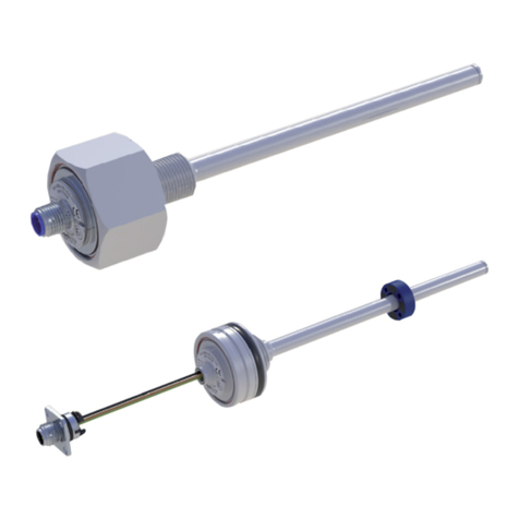
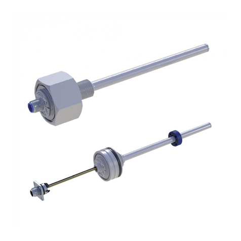
The TMI series is a magnetostricitve transducer for direct,
accurate measurement of travel in display- or feedback
applications.
2Safety instructions
Our products are regularly not approved for aeronautic or
aerospace applications and are not allowed to be used in
nuclear or military, in particular ABC-relevant applications.
For more information see our Terms and Conditions.
2.1 Intended use
The transducer is intended to be installed in a machine or
system. Together with a controller (e.g. PLC) it comprises a
position measuring system and may only be used for this
purpose.
Unauthorized modifications, improper usage or non-
observance of the instructions for installation will result in
the loss of warranty and liability claims.
2.2 Installation & startup
The transducer must be installed by qualified personnel in
consideration of all relevant safety regulations.
All necessary safety measures to protect personnel and
property in case of a transducer defect or failure must be
taken before startup.
2.3 Check connections
Improper connections and overvoltage can damage the
transducer.
Check the connections always carefully before turning-on
system.
Potential differences between supply voltage
GND and signal GND must be avoided.
With different potentials between supply voltage
GND and signal GND the transducer can be
destroyed!
2.4 Turning on the system
The system may execute uncontrolled movements
during first turning-on mainly when the transducer is
part of a control system whose parameters have not
yet been set. Therefore make sure that hereof no
dangers for personal and property can result.
2.5 Check measured values
After replacement of a transducer, it is advisable to verify
the output values for start- and end position of the position
marker in manual mode.
(Transducers are subject to modification or manufacturing
tolerances)
2.6 Check functionality
The functionality of the transducer and all its associated
components should be regularly checked and recorded.
2.7 Failure malfunction
If the transducer doesn‘t operate properly, it should be
taken out of service and protected against unauthorized
use.
1Allgemeine Beschreibung
Die Baureihe TMI ist ein magnetostriktiver Wegaufnehmer
für die direkte, genaue und absolute Messung von Wegen
bzw. Längen in der Steuerungs-, Regelungs- und
Messtechnik.
2 Sicherheitshinweise
Unsere Produkte sind regelmäßig nicht für Luft- und
Raumfahrtanwendungen zugelassen und dürfen nicht
in kerntechnischen oder militärischen, insbesondere
ABC-relevanten Applikationen verwendet werden.
Weitere Informationen s. unsere AGBs.
2.1 Bestimmungsgemäße Verwendung
Der Wegaufnehmer wird zu seiner Verwendung in eine
Maschine oder Anlage eingebaut. Er bildet zusammen mit
einer Steuerung (z.B. SPS) ein Wegmesssystem und darf
auch nur für diese Aufgabe eingesetzt werden.
Unbefugte Eingriffe, nicht bestimmungsgemäße
Verwendung oder Nichtbeachtung der Montagehinweise
führen zum Verlust von Gewährleistungs-, Garantie- und
Haftungsansprüchen.
2.2 Installation & Inbetriebnahme
Der Wegaufnehmer ist nur von Fachpersonal und unter
Berücksichtigung aller geltenden Sicherheitsvorschriften
in Betrieb zu nehmen.
Alle Maßnahmen zum Schutz von Personen und Sachen
bei einem Defekt des Wegaufnehmers müssen vor der
Inbetriebnahme getroffen werden.
2.3 Anschlüsse prüfen
Falsche Verbindungen und Überspannung können zur
Beschädigung des Wegaufnehmers führen.
Prüfen Sie deshalb vor dem Einschalten die Anschlüsse
immer sorgfältig.
Potentialdifferenzen zwischen Versorgung GND
und Signal GND sind zu vermeiden.
Durch Potentialdifferenzen zwischen Versorgung
GND und Signal GND kann der Wegaufnehmer
zerstört werden!
2.4 Einschalten des Systems
Das System kann beim Einschalten unkontrollierte
Bewegungen ausführen, vor allem wenn der
Wegaufnehmer Teil eines Regelsystems ist,
dessen Parameter noch nicht eingestellt sind.
Stellen Sie daher sicher, dass hiervon keine
Gefahren für Personen und Sachen ausgehen
können.
2.5 Messwerte prüfen
Nach dem Austausch eines Wegaufnehmers wird
empfohlen, die Ausgangswerte in der Anfangs- und
Endstellung des Positionsgebers im Handbetrieb zu
überprüfen. (Änderungen oder fertigungsbedingte
Streuungen vorbehalten)
2.6 Funktionsfähigkeit prüfen
Die Funktionsfähigkeit des Wegaufnehmers und aller
damit verbundenen Komponenten sind regelmäßig zu
überprüfen und zu protokollieren.
2.7 Funktionsstörung
Wenn der Wegaufnehmer nicht ordnungsgemäß arbeitet,
ist es außer Betrieb zu nehmen und gegen unbefugte
Benutzung zu sichern.
Artikelnummer / Item number: 516684/04 Änderungen vorbehalten / Subject to change without notice 2012/02 Seite / page 2
TMI Gebrauchsanleitung
TMI Manual
4Montagehinweis
Für die direkte Hubmessung im Zylinder wird der
Positionsgeber mit 2 Schrauben M3 oder M4 (je nach
Positionsgeber ) direkt auf dem Kolbenboden montiert.
Alternativ kann der Positionsgeber auch durch einen
Schraubring oder eine Einpressverbindung fixiert werden.
Für die Aufnahme des magnetischen Positionsgebers ist
möglichst nichtmagnetisches Material (z.B. Edelstahl,
Messing, Aluminium) zu verwenden. Gegebenenfalls ist
eine nichtmagnetische Distanzscheibe (min. 5 mm stark)
zwischen Positionsgeber und Kolbenboden zu montieren.
Der Positionsgeber darf nicht auf dem Stab schleifen.
Wird der Schraubflansch in einen Zylinder aus
magnetisierbarem Material eingebaut, dann ist unbedingt
darauf zu achten, dass der Abstand zwischen
Positionsgeber in der Nullpunktstellung und dem Zylinder
min. 15 mm axial beträgt!
Bei den Varianten mit mehreren Positionsgebern muss
der Abstand zwischen den Positionsgebern jeweils min.
100 mm betragen!
Starke elektrische oder magnetische Felder in
unmittelbarer Nähe des Wegaufnehmers können
zu fehlerhaften Signalen führen.
Der Sensor wird mit Hilfe des Sechskantflansches (SW46)
eingeschraubt. Das Anschraubmoment darf 50Nm nicht
überschreiten!
Die Bohrung in der Kolbenstange ist abhängig vom Druck
und der Verfahrgeschwindigkeit auszulegen. Der
empfohlene Bohrungsdurchmesser beträgt Dk ≥12,7 mm.
Der mitgelieferte O-Ring dichtet den Druckbereich des
Zylinders am Einschraubloch ab. Die Flanschauflagefläche
muss vollständig an der entsprechenden Auflagefläche des
Zylinders aufliegen.
Bei waagrechter Montage von Wegaufnehmern mit einem
elektrisch definierten Bereich über 1000 mm empfiehlt es
sich, den TMI-Stab am Ende abzustützen.
Das Ende des TMI-Stabes ist vor Verschleiß zu schützen.
Der Bereich für den Kabelabgang muss ausreichend
dimensioniert werden, der Mindestbiegeradius ist
einzuhalten und scharfe Kanten sind zu vermeiden!
5Anschlüsse
Beim elektrischen Anschluss unbedingt zu beachten:
Anlage (Versorgung GND) und Schaltschrank (Signal GND)
müssen auf gleichem Potential liegen.
Um die elektromagnetische Verträglichkeit (EMV) zu
gewährleisten, sind nachfolgende Hinweise unbedingt zu
beachten:
• Wegaufnehmer und Steuerung müssen mit einem
geschirmten Kabel verbunden werden.
• Schirmung: Geflecht aus Kupfer-Einzeldrähten,
85% Bedeckung.
• Auf der Seite der Steuerung muss der Kabelschirm
geerdet, d.h. mit dem Schutzleiter verbunden werden.
Anschlusskabel darf nicht auf über 30m
verlängert werden!
4Instruction for installation
For direct stroke measuring in a cylinder the position marker
has to be fixed with 2 screws M3 or M4 (depending on the
position marker) directly on the cylinder‘s piston bottom.
Alternatively the position marker can also be fixed by a
threaded ring or by an press-fit-connection. For the mounting
of the position marker non-magnetic material (e.g. stainless
steel, brass, aluminum) has to be used preferably.
If necessary a non-magnetic spacer with min. 5 mm thickness
has to be mount between position marker and cylinder‘s
piston bottom. The position marker may not drag on the rod.
When the screw flange will be mounted in a cylinder of
magnetizable material, it‘s important to have axially a
electrical spacing of min. 15 mm between position marker in
setting to zero point and cylinder!
For the versions with several position markers the distance
between the position markers must be min. 100 mm!
Strong electrical or magnetic fields in the
immediate vicinity of the transducer may lead to
faulty signals.
The sensor has to be screwed in via the hexagon flange
(SW46). The maximum tightening torque must never
exceed 50 Nm when fastening down the sensor head!
The bore in the piston rod has to be laid out dependent on
the pressure and the velocity of the movement.
The recommended bore diameter amounts to Dk ≥12,7 mm.
The provided O-ring seals the pressure area of the cylinder at
the screw plug hole. The contact surface of the flange must
rest completely against the mounting surface of the cylinder.
For horizontal mounting of transducer with a defined
electrical range longer than 1000 mm the TMI rod should be
supported or attached at ist end.
The end of the TMI rod has to be protected against wear.
For the area of the cable please take care that enough space
is available, the minimum bending radius has been observed
and sharp edges have be avoided.
5 Wiring
Note the following when making electrical connection:
System (supply voltage GND) and control cabinet (signal
GND) must be at the same potential.
To ensure the electromagnetic compatibility (EMC), the
following instructions must be strictly followed:
• Transducer and controller must be connected by using a
shielded cable.
• Shielding: Copper filament braided, 85% coverage.
• On the controller side the cable shield must be grounded,
i.e. be connected with the protective earth conducter.
Cable connection may not extended over 30m!
3Elektrische Daten / Electrical data
Versorgungsspannung / Supply voltage: 24 VDC (siehe auch Datenblatt / see also data sheet)
Stromaufnahme / Current draw: ≤100 mA typisch / typical
Artikelnummer / Item number: 516684/04 Änderungen vorbehalten / Subject to change without notice 2012/02 Seite / page 3
TMI Gebrauchsanleitung
TMI Manual
Artikelnummer / Item number: 516684/04 Änderungen vorbehalten / Subject to change without notice 2012/02 Seite / page 4
Zubehör / accessories
Positionsgeber Z-TMI-P02 oder Z-TMI-P14
postion marker Z-TMI-P02 or Z-TMI-P14
24,5 8
M16x0,75
13,5 70 ±130 L60
10,5
0,5
∅10
elektrischer Nullpunkt
electrical zero point
6Einbau / Installation
6.1 Flansch / Flange
G
Code 002 M18x1,5
Code 003 3/4"-16UNF
O-Ring
o-ring seal
Einzelheit X, Maßstab 2:1
Detail X, scale 2:1
∅25
G
0,5
Zubehör / accessories
Positionsgeber Z-TMI-P02 oder Z-TMI-P14
postion marker Z-TMI-P02 or Z-TMI-P14
elektrischer Nullpunkt
electrical zero point
13,5
8
60
L
70 ±151
24,510,5
M16x0,75
∅10
G
Code 004 M18x1,5
Code 005 3/4"-16UNF
O-Ring
o-ring seal
Einzelheit X, Maßstab 2:1
Detail X, scale 2:1
G
SW 46
53 -1,5
SW 46
53 -1,5
TMI Gebrauchsanleitung
TMI Manual
Artikelnummer / Item number: 516684/04 Änderungen vorbehalten / Subject to change without notice 2012/02 Seite / page 5
Einzelheit X, nichtmagnetisierbarer Werkstoff
Detail X, non-magnetizable material
min.22
Z-TMI-P02 /
Z-TMI-P14
S
M18x1,5
O-Ring
o-ring seal
∅15,4x2,1
N
elektrischer Nullpunkt
electrical zero point
∅Dk siehe / see 4
∅Dk
A
O-Ring
o-ring seal
∅15,4x2,1
Zylinder
cylinder
Kolbenstange mit Kolben
piston rod with piston
min. Biegeradius 50mm für
NT-Standardkabel (∅6 ±0,2)
min. bending radius 50mm for
NT-standard cable (∅6 ±0,2)
Zubehör / accessories
Positionsgeber Z-TMI-P02 oder Z-TMI-P14
position marker Z-TMI-P02 or Z-TMI-P14
S
M18x1,5
O-Ring
o-ring seal
∅15,4x2,1
Z-TMI-P02 /
Z-TMI-P14
Einzelheit X, magnetisierbarer Werkstoff
Detail X, magnetizable material
elektrischer Nullpunkt
electrical zero point
min.5
nichtmagnetisierbare Distanz-
scheibe,
non-magnetizable spacer
min.15
N S
Code 002 30 ∅25
Code 004 51 -
N S
C o de 0 02 3 0 ∅25
C o de 0 04 5 1 -
Einschraubbohrung nach ISO 6149
(ohne O-Ring dargestellt)
screw plug hole per ISO 6149
(shown without o-ring seal)
M18x1,5
Einzelheit Y
Detail Y 2,4 +0,4
0,1
A
A
A
0,2
∅19,8 +0,1
6.1.2 Gewinde / Thread M18x1,5
TMI Gebrauchsanleitung
TMI Manual
Artikelnummer / Item number: 516684/04 Änderungen vorbehalten / Subject to change without notice 2012/02 Seite / page 6
∅Dk siehe / see 4
∅Dk
A
O-Ring
o-ring seal
∅15,3x2,4
Zylinder
cylinder
Kolbenstange mit Kolben
piston rod with piston
min. Biegeradius 50mm für
NT-Standardkabel (∅6 ±0,2)
min. bending radius 50mm for
NT-standard cable (∅6 ±0,2)
Zubehör / accessories
Positionsgeber Z-TMI-P02 oder Z-TMI-P14
position marker Z-TMI-P02 or Z-TMI-P14
N S
Code 003 30 ∅25
Code 005 51 -
N
elektrischer Nullpunkt
electrical zero point
Einzelheit X, nichtmagnetisierbarer Werkstoff
Detail X, non-magnetizable material
O-Ring
o-ring seal
∅15,3x2,4
S
3/4“-16UNF
min.22
Z-TMI-P02 /
Z-TMI-P14
N S
C o de 0 02 3 0 ∅25
C o de 0 04 5 1 -
Einschraubbohrung nach SAE J475
(ohne O-Ring dargestellt)
screw plug hole per SAE J475
(shown without o-ring seal)
3/4"-16UNF
Einzelheit Y
Detail Y 2,6
0,1
A
A
A
0,2
∅20,6 +0,1
Z-TMI-P02 /
Z-TMI-P14
3/4“-16UNF
O-Ring
o-ring seal
∅15,3x2,4
Einzelheit X, magnetisierbarer Werkstoff
Detail X, magnetizable material
min.15 min.5
elektrischer Nullpunkt
electrical zero point
nichtmagnetisierbare Distanz-
scheibe,
non-magnetizable spacer
S
6.1.3 Gewinde / Thread 3/4"-16UNF
TMI Gebrauchsanleitung
TMI Manual
Artikelnummer / Item number: 516684/04 Änderungen vorbehalten / Subject to change without notice 2012/02
6.2 Positionsgeber / Position marker
Z-TMI-P02
18,5
8
∅25
∅3,2
∅12,5
Z-TMI-P10 (Füllstandsmessung / level measuring)
Z-TMI-P11 (Füllstandsmessung / level measuring)
∅32,5
53
6,6
1,4
∅32,5
Innen/Inside-∅11,7
Innen/Inside-∅11,7
0,8 0,8
50,8
∅51,1
22,5
3,2
8
∅32
∅13
∅4,3
∅4,3
∅8
24
Z-TMI-P14 8
Seite / page 7
TMI Gebrauchsanleitung
TMI Manual
Artikelnummer / Item number: 516684/04 Änderungen vorbehalten / Subject to change without notice 2012/02 Seite / page 8
13,5
M16x0,75
7Elektrischer Anschluss / Electrical connection
7.1 Code 101 / 103
7.2 Code 102
7.3 Code 201 / 203 / 205
TMI Gebrauchsanleitung
TMI Manual
Artikelnummer / Item number: 516684/04 Änderungen vorbehalten / Subject to change without notice 2012/02
7.4 Steckerbelegung / Pin configuration
( Sicht auf den Flanschstecker / front view to the flange connector)
Flanschstecker 8-pol. / 8 pin flange connector
IEC130-9, DIN 45326
Beispiel Teileschlüssel / example ordering code: TMI-____-___-___-101
Zubehör / accessories: Kupplungsdose / straight connector EEM 33-84; IP67; Art.-Nr. / P/N 005627
Winkeldose / angled connector EEM 33-85; IP67; Art.-Nr. / P/N 005628
Flanschstecker 8-pol. / 8 pin flange connector
M12x1, DIN EN 50044
Beispiel Teileschlüssel / example ordering code: TMI-____-___-___-102
Zubehör / accessories: Kupplungsdose / straight connector EEM 33-86; IP67; Art.-Nr. / P/N 005629
Winkeldose / angled connector EEM 33-87; IP67; Art.-Nr. / P/N 005630
Flanschstecker 6-pol. / 6 pin flange connector
IEC130-9, DIN 45326
Beispiel Teileschlüssel / example ordering code: TMI-____-___-___-103
Zubehör / accessories: Kupplungsdose / straight connector EEM 33-82; IP67; Art.-Nr. / P/N 005639
Winkeldose / angled connector EEM 33-94; IP67; Art.-Nr. / P/N 005648
Spezifische Stecker auf Anfrage / Special connectors on request :
( Sicht auf den Flanschstecker / front view to the flange connector)
Weitere spezifische Stecker auf Anfrage / Additional special connectors on request :
Teileschlüssel / ordering code: TMI-____-___-___-111
Abmessungen siehe / dimensions see TMI-____-___-___-103
Seite / page 9
TMI Gebrauchsanleitung
TMI Manual
Artikelnummer / Item number: 516684/04 Änderungen vorbehalten / Subject to change without notice 2012/02
8 Ausgangssignale / Output Signals
8.1 Impuls-Schnittstelle / Pulse interface
Beispiel Teileschlüssel: TMI-____-___-1__-___
Example ordering code : TMI-____-___-1__-___
START/STOP
START/STOP
START/STOP
START/STOP
INIT
INIT
tmess = d
Stecker /
Plug
Code 101,102
Kabel / Cable
Code 201, 203, 205
Dose m. Kabel /
Connector w. Cable
EEM33-86, EEM33-87
Signal
PIN 1 YE gelb / yellow WH weiss / white +INIT
PIN 2 GY grau / grey
BN braun /
brown
+Start/Stop
PIN 3 PK rosa / pink GN grün / green -INIT
PIN 4 RD rot / red YE gelb / yellow offen / open
PIN 5 GN grün / green GY grau / grey -Start/Stop
PIN 6 BU blau / blue PK rosa / pink Versorgung GND /
supply voltage GND
PIN 7
BN braun /
brown
BU blau / blue +24 VDC
PIN 8 WH weiss / white RD rot / red offen / open
8.2 SSI-Schnittstelle / SSI Interface
Beispiel Teileschlüssel: TMI-____-___-2__-___
Example ordering code : TMI-____-___-2__-___
Stecker / Plug
Code 101,102
Kabel / Cable
Code 201, 203, 205
Dose m. Kabel /
Connector w. Cable
EEM33-86, EEM33-87
Signal
PIN 1 YE gelb / yellow WH weiss / white +Clk
PIN 2 GY grau / grey
BN braun /
brown
+Data
PIN 3 PK rosa / pink GN grün / green -Clk
PIN 4 RD rot / red YE gelb / yellow offen / open
PIN 5 GN grün / green GY grau / grey -Data
PIN 6 BU blau / blue PK rosa / pink Versorgung GND /
supply voltage GND
PIN 7
BN braun /
brown
BU blau / blue +24 VDC
PIN 8 WH weiss / white RD rot / red offen / open
Konfektionierte Kabel können abweichende Farbbelegung aufweisen!
Customized cable may show different color coding!
Konfektionierte Kabel können abweichende Farbbelegung aufweisen!
Customized cable may show different color coding!
8.3 DyMoS-Schnittstelle / DyMoS Interface
Beispiel Teileschlüssel: TMI-____-___-3__-___
Example ordering code : TMI-____-___-3__-___
Stecker / Plug
Code 101,102
Kabel / Cable
Code 201, 203, 205
Doser m. Kabel /
Connector w. Cable
EEM33-86, EEM33-87
Signal
PIN 1 YE gelb / yellow WH weiss / white +Clk
PIN 2 GY grau / grey BN braun / brown +Data1
PIN 3 PK rosa / pink GN grün / green -Clk
PIN 4 RD rot / red YE gelb / yellow -Data2
PIN 5 GN grün / green GY grau / grey -Data1
PIN 6 BU blau / blue PK rosa / pink Versorgung GND /
supply voltage GND
PIN 7 BN braun / brown BU blau / blue +24 VDC
PIN 8 WH weiss / white RD rot / red +Data2
Konfektionierte Kabel können abweichende Farbbelegung aufweisen!
Customized cable may show different color coding!
Seite / page 10
TMI Gebrauchsanleitung
TMI Manual
Artikelnummer / Item number: 516684/04 Änderungen vorbehalten / Subject to change without notice 2012/02
8.4 Analoge Schnittstellen / Analog Output
Beispiel Teileschlüssel: TMI-____-___-4__-___
Example ordering code : TMI-____-___-4__-___
Stecker / Plug
Code 101,102
Kabel / Cable
Code 201, 203, 205
Dose m. Kabel /
Connector w. Cable
EEM33-86, EEM33-87
Signal
PIN 1 YE gelb / yellow WH weiss / white 0(4)...20 mA
PIN 2 GY grau / grey BN braun / brown
Signal GND /
signal GND
PIN 3 PK rosa / pink GN grün / green 10...0 VDC
PIN 4 RD rot / red YE gelb / yellow DIAG*
PIN 5 GN grün / green GY grau / grey 0...10 VDC
PIN 6 BU blau / blue PK rosa / pink Versorgung GND /
supply voltage GND
PIN 7 BN braun / brown
BU blau / blue +24 VDC
PIN 8 WH weiss / white RD rot / red PROG*
=
8.5 Analoge Schnittstellen / Analog Output
Option 2 Positionsgeber / Dual Output Option
Nur Teileschlüssel: TMI-____-___-412-___
Only ordering code : TMI-____-___-412-___
Stecker / Plug
Code 101,102
Kabel / Cable
Code 201, 203, 205
Dose m. Kabel /
Connector w. Cable
EEM33-86, EEM33-87
Signal
PIN 1 YE gelb / yellow WH weiss / white offen / open
PIN 2 GY grau / grey BN braun / brown
Signal GND /
signal GND
PIN 3 PK rosa / pink GN grün / green 0...10 VDC (Pos.1)
PIN 4 RD rot / red YE gelb / yellow DIAG*
PIN 5 GN grün / green GY grau / grey 0...10 VDC (Pos.2)
PIN 6 BU blau / blue PK rosa / pink Versorgung GND /
supply voltage GND
PIN 7 BN braun / brown
BU blau / blue +24 VDC
PIN 8 WH weiss / white RD rot / red PROG*
=
Konfektionierte Kabel können abweichende Farbbelegung aufweisen!
Customized cable may show different color coding!
*) Nur für Teach-In-Funktion anschließen (siehe auch Seite 12).
*) Connect only for Teach-In function (see also page 12).
Konfektionierte Kabel können abweichende Farbbelegung aufweisen!
Customized cable may show different color coding!
*) Nur für Teach-In-Funktion anschließen (siehe auch Seite 12).
*) Connect only for Teach-In function (see also page 12).
Seite / page 11
TMI Gebrauchsanleitung
TMI Manual
Artikelnummer / Item number: 516684/04 Änderungen vorbehalten / Subject to change without notice 2012/02
9Spezifische Stecker auf Anfrage / Special connectors on request
9.1 Flanschstecker 6-pol. / 6 pin flange connector
IEC130-9, DIN 45326
Beispiel Teileschlüssel: TMI-____-___-___-103
Example ordering code : TMI-____-___-___-103
Stecker / Plug Signal
0...10 VDC
Signal
0(4)...20 mA
Signal
SSI
Signal
Start/Stop
PIN 1 0...10 VDC 0(4)...20 mA - Data - Start/Stop
PIN 2 Signal GND /
signal GND
Signal GND /
signal GND
+ Data + Start/Stop
PIN 3 10...0 VDC + Clk + INIT
PIN 4 Versorgung GND /
supply voltage GND
Versorgung GND /
supply voltage GND
- Clk - INIT
PIN 5 +24 VDC +24 VDC +24 VDC +24 VDC
PIN 6 Versorgung GND /
supply voltage GND
Versorgung GND /
supply voltage GND
Versorgung GND /
supply voltage GND
Versorgung GND /
supply voltage GND
9.2 Flanschstecker 6-pol. / 6 pin flange connector
IEC130-9, DIN 45326
Beispiel Teileschlüssel: TLM - _ _ _ _ - _ _ _ - _ _ _ - 111
Example ordering code : TLM - _ _ _ _ - _ _ _ - _ _ _ - 111
Stecker / Plug Signal
0...10 VDC Signal
0(4)...20 mA
PIN 1 0...10 VDC 0(4)...20 mA
PIN 2 Signal GND /
signal GND
Signal GND /
signal GND
PIN 3 DIAG* DIAG*
PIN 4 PROG* PROG*
PIN 5 +24 VDC +24 VDC
PIN 6 Versorgung GND /
supply voltage GND
Versorgung GND /
supply voltage GND
=
*) Nur für Teach-In-Funktion anschließen (siehe auch Seite 11).
*) Connect only for Teach-In function (see also page 11).
Seite / page 12
TMI Gebrauchsanleitung
TMI Manual
Artikelnummer / Item number: 516684/04 Änderungen vorbehalten / Subject to change without notice 2012/02
10 Teach-In Funktion für analoge Varianten
10.1 Beschreibung
Beim TMI mit Analogschnittstellen kann die Start- und
Endposition für bis zu zwei Positionsgeber nachträglich über
zwei Steckerpins justiert werden, um den(die)
Verstellbereich(e) anwendungsspezifisch neu festzulegen.
Der Ausgangsbereich (0..10 V / 10..0 V / 0..20 mA / usw.)
kann dann abhängig vom tatsächlichen Verfahrweg beliebig
definiert werden.
Nach der Umprogrammierung bleibt die Linearitätskorrektur
aktiv.
10.2 Programmierung
Positionsgeber in die zu programmierende Startposition(en)
bringen. Der Programmiermodus wird aktiviert, wenn für mind.
3 s ein High-Pegel an Pin 8 anliegt. Eine High-Low Flanke an
Pin 4 mit einer anschließenden Wartezeit von mind. 3 s setzt
die Startposition(en). Dann wird/werden der/die
Positionsgeber auf die Endposition gesetzt.
Eine weitere High-Low Flanke mit einer Wartezeit von mind. 3
s setzt die Endposition(en). Der Low-Pegel an Pin 4
wird zurückgenommen und danach Pin 8 in den Ruhezustand
versetzt. Mit der gültigen Übernahme der Endposition(en) wird
der interne Programmiervorgang gestartet.
Bei einem System mit zwei Positionsgebern werden immer
beide Positionen gleichzeitig übernommen.
Ist der Programmierablauf nicht innerhalb 60 s
abgeschlossen, d.h. die Zeit zwischen der steigenden Flanke
an Pin 8 (PROG) und der Übernahme der Endposition(en) ist
> 60 s, dann werden die gesetzten Start-/Endpunkte ignoriert
und nicht in den EEPROM übernommen.
Bedingungen für eine erfolgreiche Programmierung:
- Timing muss eingehalten werden
- Die Endposition(en) muss/müssen größer als die
Startposition(en) sein
- Es darf kein Fehlerfall vorhanden sein, d.h. bei einem
System mit 2 Magneten müssen beide Magnete
gleichzeitig vorhanden sein.
Im inaktiven Zustand liegt PROG auf 0 V (interner Pull-Down)
und DIAG auf 24 V (interner Pull-Up).
10.3 Zurücksetzen in den Auslieferungszustand
Das Zurücksetzen in den ursprünglichen Zustand (Teach-In
Mode deaktiviert) wird nach dem selben Ablauf wie die
Programmierung durchgeführt. Dabei muss entweder
- die Endposition(en) muss/müssen) kleiner oder gleich der
StartPosition(en) sein oder
- ein Fehlerfall erzeugt werden (Programmierablauf bei
fehlendem Magneten durchführen).
10 Teach-in function for analog models
10.1 Description
The start and end position on TMI transducers with analog
interfaces can be adjusted for application specific purposes.
The output range (0..10 V / 10..0 V / 0..20 mA / etc.) can be
completely redefined. Up to two position markers can be
recalibrated at the same time via two connector pins and a
simple programming procedure.
After reprogramming the specified linearity is still guaranteed.
10.2 Programming
The position marker(s) has to be placed at the desired new
start position(s). The programming mode will be activated
when high level is applied at connector pin 8 (PROG) for at
least 3 seconds. After that a high to low transition at pin 4
(DIAG) with a minimum duration of 3 seconds will set the start
position(s). Then the position marker(s) has to be placed at
the desired end position(s). The next high to low transition
with a low level of at least 3 seconds will set the end
position(s). Now the low level at pin 4 and then the high level
at pin 8 has to be taken back.
If a system with two position markers is used, always both
positions are reprogrammed at the same time.
If the programming procedure is not completed within 60
seconds, i.e. the time between the rising edge at pin 8
(PROG) and the take over of the end position exceeds 60
seconds, the start/end position is ignored and not
programmed into the transducer's EEPROM.
Conditions for successive programming:
- the timing has to meet the conditions
- the end position(s) must be greater than the start position(s)
- an error condition must not be present, e.g. if a system with
two magnets is used, both magnets have to be functional
In inactive state the PROG pin is at 0 V (internal pull-down
resistor) and the DIAG pin is at 24 V (internal pull-up).
So the two pins do not have to be connected when
programming is not required.
10.3 Reset to original state
The transducer can be reset into the original delivery state
(teach-in deactivated) using the same procedure than
programming with one of the following exceptions:
- the end position(s) must be lower or equal than the start
position(s) or
- an error condition is met (programming procedure with
missing magnet is executed).
Seite / page 13
take over the
start position(s) into RAM
take over the
end position(s) and save new values
TMI Gebrauchsanleitung
TMI Manual
Artikelnummer / Item number: 516684/04 Änderungen vorbehalten / Subject to change without notice 2012/02
TMI-____-___-___-___
Elektrischer Messbereich /
Electrical measuring range
Mechanische Ausführung /
Mechanical configuration Elektrische Schnittstelle /
Electrical interface
Elektrischer Anschluss/
Electrical connection
11 Notwendiges Zubehör
• Ring-Positionsgeber Z-TMI-P02 (Art.Nr. 005652)
• Ring-Positionsgeber Z-TMI-P14 (Art.Nr. 005657)
• Schwimmender Positionsgeber Z-TMI-P10 (Art.Nr. 005662)
• Schwimmender Positionsgeber Z-TMI-P11 (Art.Nr. 005663)
12 Optionales Zubehör
• Kupplungsdose IEC 130-9:
6-pol., EEM 33-82 (Art.Nr. 005639)
8-pol., EEM 33-84 (Art.Nr. 005627)
• Winkeldose IEC 130-9:
6-pol., EEM 33-94 (Art.Nr. 005648)
8-pol., EEM 33-85 (Art.Nr. 005628)
• PUR-Kabel mit 8-pol. Kupplungsdose,
M12x1, 8x0,25 mm², geschirmt:
2m Länge, EEM 33-86 (Art.Nr. 005629)
5m Länge, EEM 33-90 (Art.Nr. 005635)
10m Länge, EEM 33-92 (Art.Nr. 005637)
• PUR-Kabel mit 8-pol. Winkeldose,
M12x1, 8x0,25 mm², geschirmt:
2m Länge, EEM 33-87 (Art.Nr. 005630)
5m Länge, EEM 33-91 (Art.Nr. 005636)
10m Länge, EEM 33-93 (Art.Nr. 005638)
• Kupplungsdose M12x1, 5-pol., EEM 33-73
(Art.Nr. 005645)
• Winkeldose M12x1, 5-pol., EEM 33-75
(Art.Nr. 005646)
13 Bestellcode / Ordering code
11 Accessories (order separately)
• Ring position marker Z-TMI-P02 (P/N 005652)
• Ring position marker Z-TMI-P14 (P/N 005657)
• Float position marker Z-TMI-P10 (P/N 005662)
• Float position marker Z-TMI-P11 (P/N 005663)
12 Optional accessories
• Straight connector IEC130-9:
6-pin, EEM 33-82 (Part No. 005639)
8-pin, EEM 33-84 (Part No. 005627)
• Angled connector IEC 130-9:
6-pin, EEM 33-94 (Part No. 005648)
8-pin, EEM 33-85 (Part No. 005628)
• PUR-cable with 8-pin female connector,
M12x1, 8x0,25 mm², shielded:
2m length, EEM 33-86 (Part No. 005629)
5m length, EEM 33-90 (Part No. 005635)
10m length, EEM 33-92 (Part No. 005637)
• PUR-cable with 8-pin female angled connector,
M12x1, 8x0,25 mm², shielded:
2m length, EEM 33-87 (Part No. 005630)
5m length, EEM 33-91 (Part No. 005636)
10m length, EEM 33-93 (Part No. 005638)
• Straight connector, M12x1, 5-pin, EEM 33-73
(Part No. 005645)
• Angled connector M12x1; 5-pin, EEM 33-75
(Part No. 005646)
Seite / page 14

Other novotechnik Transducer manuals

novotechnik RSC-2800 User manual

novotechnik

novotechnik RSC-2800 User manual

novotechnik TP1 Series User manual

novotechnik

novotechnik TP1 Series User manual

novotechnik PTP Series User manual

novotechnik

novotechnik PTP Series User manual

novotechnik TLM 102 Series User manual

novotechnik

novotechnik TLM 102 Series User manual

novotechnik LS1 Series User manual

novotechnik

novotechnik LS1 Series User manual

novotechnik TH1 CANopen User manual

novotechnik

novotechnik TH1 CANopen User manual

novotechnik RFC-4800 CAN User manual

novotechnik

novotechnik RFC-4800 CAN User manual

novotechnik LWG Series User manual

novotechnik

novotechnik LWG Series User manual

novotechnik TH1 Series User manual

novotechnik

novotechnik TH1 Series User manual

novotechnik RSM-2800 User manual

novotechnik

novotechnik RSM-2800 User manual

novotechnik T Series User manual

novotechnik

novotechnik T Series User manual

novotechnik TIM Series User manual

novotechnik

novotechnik TIM Series User manual

novotechnik TH1 Series User manual

novotechnik

novotechnik TH1 Series User manual

novotechnik TM1 Series User manual

novotechnik

novotechnik TM1 Series User manual

novotechnik TX2 Series User manual

novotechnik

novotechnik TX2 Series User manual

novotechnik TIM Series User manual

novotechnik

novotechnik TIM Series User manual

novotechnik TLH User manual

novotechnik

novotechnik TLH User manual

novotechnik TEX Series User manual

novotechnik

novotechnik TEX Series User manual

novotechnik RSM-2800 User manual

novotechnik

novotechnik RSM-2800 User manual

novotechnik TM1 Series User manual

novotechnik

novotechnik TM1 Series User manual

novotechnik Z-TF1-PO1 User manual

novotechnik

novotechnik Z-TF1-PO1 User manual

novotechnik LWX Series User manual

novotechnik

novotechnik LWX Series User manual

Popular Transducer manuals by other brands

Electro-Voice DH1012 Specification sheet

Electro-Voice

Electro-Voice DH1012 Specification sheet

Airmar P79S Owner's guide & installation instructions

Airmar

Airmar P79S Owner's guide & installation instructions

Tecsis P3230 instruction manual

Tecsis

Tecsis P3230 instruction manual

Garmin gWind Wireless 2 installation instructions

Garmin

Garmin gWind Wireless 2 installation instructions

HBM T5 Mounting instructions

HBM

HBM T5 Mounting instructions

SIAP+MICROS t018 TTP User manual and maintenance

SIAP+MICROS

SIAP+MICROS t018 TTP User manual and maintenance

Iskra MT 511 user manual

Iskra

Iskra MT 511 user manual

Electro-Voice 3-Inch High Frequency Neodymium Transducer... Technical specifications

Electro-Voice

Electro-Voice 3-Inch High Frequency Neodymium Transducer... Technical specifications

Fishman SBT-C installation guide

Fishman

Fishman SBT-C installation guide

Airmar TM256 Owner's guide & installation instructions

Airmar

Airmar TM256 Owner's guide & installation instructions

Furuno SS542 Owner's guide & installation instructions

Furuno

Furuno SS542 Owner's guide & installation instructions

Minebea TMOFB-NM Series instruction manual

Minebea

Minebea TMOFB-NM Series instruction manual

C-ducer CP Series User handbook

C-ducer

C-ducer CP Series User handbook

KYOWA ASH-A-10 instruction manual

KYOWA

KYOWA ASH-A-10 instruction manual

Lumel P18D User Manual & Quick Start

Lumel

Lumel P18D User Manual & Quick Start

Camille Bauer SINEAX F 535 operating instructions

Camille Bauer

Camille Bauer SINEAX F 535 operating instructions

CARLO GAVAZZI SPT-90 operating instructions

CARLO GAVAZZI

CARLO GAVAZZI SPT-90 operating instructions

Mianyang Weibo Electronic WBV414U05 user manual

Mianyang Weibo Electronic

Mianyang Weibo Electronic WBV414U05 user manual

manuals.online logo
manuals.online logoBrands
  • About & Mission
  • Contact us
  • Privacy Policy
  • Terms and Conditions

Copyright 2025 Manuals.Online. All Rights Reserved.