manuals.online logo
Brands
  1. Home
  2. •
  3. Brands
  4. •
  5. Controlli
  6. •
  7. Controllers
  8. •
  9. Controlli W554C User manual

Controlli W554C User manual

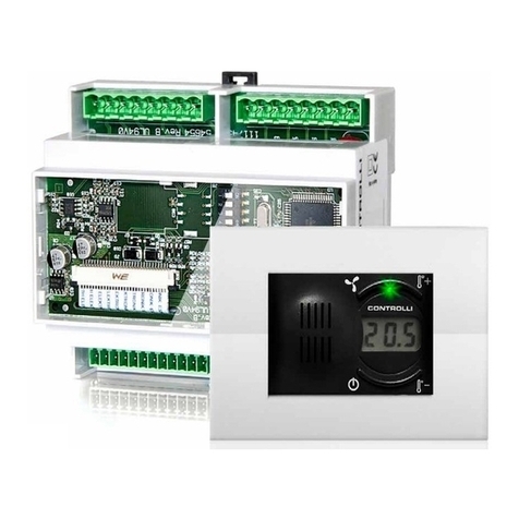
W554C
Multi-function DDC controller
1st Issue 06/11 1 DBL366E
ISO 9000
CONTROLLI
16010 SANT’OLCESE Genova - Italy
Tel.: +39 01073061 Fax: +39 0107306870/871
E-mail: [email protected] Web: www.controlli.eu
Model Description
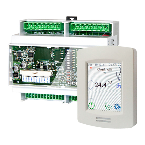
W554C Application-specic controller without display,
without RS-485 serial unit
W554C-D Application-specic controller with display,
without RS-485 serial unit
W554C-DS Application-specic controller with display,
with RS-485 serial unit
W554C-S Application-specic controller without display,
with RS-485 serial unit
GENERAL DESCRIPTION
CARATTERISTICHE TECNICHE
DDC controller for thermoventilation, tank and service water
control or swimming-pool generic loop.
The remote STA6XL sensors can be used in environment.
The controller can be connected by RS485 serial port and Mod-
Bus protocol (S version only).
Dimensions 4DIN
Max consumption 6VA / 4W
Power supply 2-24 Vac/24Vdc ± 10 % 50/60 Hz
RS485 S models only
Housing
resin plastic body PC+ABS UL94 V-0, polycarbonate
glass, thermoplastic resin buttons
Room temperature
operating -10T55°C.
storage -20T85°C
Room humidity
operating/storage 0…90% R.H.
Use Functioning device (non-safety) to in-
tegrate
Action type 1.B - 1.Y
Insulation material PTI PTI 250V (device built with III class
material)
Overvoltage category II class
Rated impulse voltage 2500V
Fire resistance degree D
Software class A
W554C-XX
W560-EXP
STA61L
ACCESSORIES
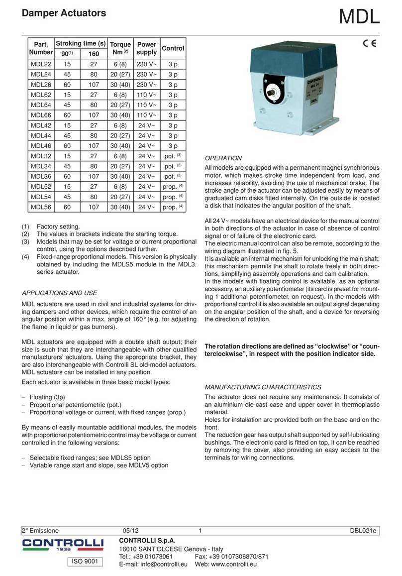
W560-EXP I/O Expansion module
W560-RT Remote Display
INPUTS/OUTPUTS
Inputs marked with * are related to congurable options and
they should be connected only if these features are enabled
and congured (see manual).
The inputs marked with ° are completely optional.
1st Issue 06/11 2 DBL366E
1: AHU. 1 coil (heating).
Set point room temperature control with minimum limit on sup-
ply. 2-stage electric coil (optional).
Room humidity control by modulating damper positioning.
TANK. Set point proportional control of tank water, with tank
water max. temperature limit (optional).
2:1 + Service water. Proportional control of set point water tem-
perature.
3:1 + Generic Loop. Set point proportional control with 0-10V
sensor or resistive sensor input. DIR/INV action set by LCD.
The controllers are able to manage the following applications; they are activated by setting the “tPCO” conguration parameter
on the display.
APPLICATION AND USE
MOUNTING
Mounting on DIN rail.
Avoid to mount the device in damp and dirty areas; it is suitable for using in environment with ordinary or normal pollution. Make
sure to leave enough space around the cooling slots of the device.
ELECTRICAL CONNECTIONS
Warning! Make the electrical connections only when the device is switched off. For the terminal rate see the label on the hous-
ing.
Do not exceed the max allowed current; in case of surplus loads, use a meter with appropriate power. Make sure that the power
supply conforms to the one required by the instrument.
The temperature sensors are not polarity-sensitive and can be extended using an ordinary bipolar cable (it is necessary to under-
line that the extension of the sensor may affect the instrument use as regards the EMC electromagnetic compatibility: the wiring
must be carried out with care).
The active sensors are characterised by a specic polarity which must be respected. It is necessary to ensure that the signal
cables (temperature/pressure sensors, digital inputs, TTL serial, RS-485 serial) are routed separately from hazardous voltage
cables. Controlli sensor use is recommended; get in touch with Sales Department for code availability.
1st Issue 06/11 3 DBL366E
B
L
A
C
K
B
L
U
E
R
E
D
W560-RT
USE TERMS - ALLOWED USE
For safety reasons the instrument must be installed and used according to the instructions provided and in particular, in normal
conditions, dangerous voltage parts must not be accessible.
The device must be adequately protected from water and dust according to the application and must also be accessible only using
tools (except for the front part).
The device is suitable for inserting into a device for home use and/or a similar one in HVAC applications and it has been tested in
relation to the safety aspects on the basis of harmonized European standards.
UNALLOWED USE
Any other different use is forbidden.
Please note that the provided relay contacts are functional and they can be damaged: possible protection devices foreseen by the
rules in force or dictated by common sense for obvious safety reasons, should be carried out outside the instrument.
WIRING DIAGRAMS
Legend
5 Vdc 5Vdc 20mA max auxiliary power supply
12 Vdc 12Vdc auxiliary power supply
N Neutral
GND Ground
LAN Remote keyboard W560-RT • room sensor
STA60L • W560-EXP expansion connection:
1 = BLACK / GND; 2 = BLUE / SIGNAL
3 = RED / +12Vdc
RS-485 RS-485 serial unit (S models only)
TTL Standard
1st Issue 06/11 4 DBL366E
ISO 9000
Automatic control systems for:
air conditioning/heating/industrial thermal process
The performances stated on this sheet can be modied without any prior notice due to design improvements.
DIMENSIONS (mm)
W554C / W560-EXP
W560-RT
Bianco
+
RS-485
LAN (LINK BUS)
Omnia PRO
Red 1
21 3 Supply
0V
12Vca1
Pay full attention
to the polarity
Cable supplied with sensor
Lenght: 2 mt
8762 Belden cable
Controller max lenght: 20 mt
SENSOR
STA61L
Red
Black
Blue
12Vac
Red
Supply
Nero
BELDEN CABLE
From the
previous
group
BLACK(-)
LIGHT (+)
8762
and terminal board:max 5cm
Contr. N°1
CONTROLLI
Lenght between supplied cable
Omnia PRO
LAN (LINK BUS)
RS-485
- + G
W h i t e
Black
Grey
Supply
-
Nero
Red
Supply
32
Blu
Rosso
12Vac
Supply Red
CONTROLLI
Contr. N°2
Supply
G
Grigio
8762
BELDEN CABLE
LIGHT (+)
BLACK(-)
To the following
group
It is necessary a
proper transfomer
and terminal board:max 5cm
Lenght between supplied cable
Cable supplied with sensor
Lenght: 2 mt
8762 Belden cable
Controller max lenght: 20 mt
Pay full attention
to the polarity
SENSOR
STA61L
CONNECTION SCHEME

This manual suits for next models

3

Other Controlli Controllers manuals

Controlli MVE522 User manual

Controlli

Controlli MVE522 User manual

Controlli MVH56E User manual

Controlli

Controlli MVH56E User manual

Controlli MVH.FC User manual

Controlli

Controlli MVH.FC User manual

Controlli NR9003 User manual

Controlli

Controlli NR9003 User manual

Controlli MVHFA User manual

Controlli

Controlli MVHFA User manual

Controlli MVC503R-MB User manual

Controlli

Controlli MVC503R-MB User manual

Controlli MVE522-65 User manual

Controlli

Controlli MVE522-65 User manual

Controlli MVC503R User manual

Controlli

Controlli MVC503R User manual

Controlli MVE5 Series User manual

Controlli

Controlli MVE5 Series User manual
Controlli Energon User manual

Controlli

Controlli Energon User manual

Controlli MVE204S User manual

Controlli

Controlli MVE204S User manual

Controlli MVE5 R Series User manual

Controlli

Controlli MVE5 R Series User manual

Controlli MVE2XX User manual

Controlli

Controlli MVE2XX User manual

Controlli MVHFA User manual

Controlli

Controlli MVHFA User manual

Controlli MVH56E User manual

Controlli

Controlli MVH56E User manual

Controlli NR9003 User manual

Controlli

Controlli NR9003 User manual

Controlli MVH56EA User manual

Controlli

Controlli MVH56EA User manual

Controlli MVE2 Series User manual

Controlli

Controlli MVE2 Series User manual

Controlli MVH56E User manual

Controlli

Controlli MVH56E User manual

Controlli MVC503R-MB User manual

Controlli

Controlli MVC503R-MB User manual

Controlli MVH56EX User manual

Controlli

Controlli MVH56EX User manual

Controlli NC7311 User manual

Controlli

Controlli NC7311 User manual

Controlli MVT5 Series User manual

Controlli

Controlli MVT5 Series User manual
Controlli DuraDrive MX40-7 User manual

Controlli

Controlli DuraDrive MX40-7 User manual

Popular Controllers manuals by other brands

GOK EN61-DS.2 Assembly and operating manual

GOK

GOK EN61-DS.2 Assembly and operating manual

Honeywell EXCEL 10 W7753A installation instructions

Honeywell

Honeywell EXCEL 10 W7753A installation instructions

LAE AT1-5 manual

LAE

LAE AT1-5 manual

AMX AXP-PLV Dimensional drawing

AMX

AMX AXP-PLV Dimensional drawing

Samson TROVIS 5724-3 Mounting and operating instructions

Samson

Samson TROVIS 5724-3 Mounting and operating instructions

GHL LEDControl4 V2 manual

GHL

GHL LEDControl4 V2 manual

Taconova RK 56 instructions

Taconova

Taconova RK 56 instructions

ELGO Electric SERIES P8721-000-P manual

ELGO Electric

ELGO Electric SERIES P8721-000-P manual

Bard LV1000-100 INSTALLATION SUPPORT MATERIALS

Bard

Bard LV1000-100 INSTALLATION SUPPORT MATERIALS

ACTUATECH GD2880 instruction manual

ACTUATECH

ACTUATECH GD2880 instruction manual

SOMFY ZWAVE to RTS INTERFACE Specifications, Installation & Operating Instructions

SOMFY

SOMFY ZWAVE to RTS INTERFACE Specifications, Installation & Operating Instructions

Danfoss AME 610 instructions

Danfoss

Danfoss AME 610 instructions

AMDAR BERMAD BR735D-UPS quick start guide

AMDAR

AMDAR BERMAD BR735D-UPS quick start guide

AUMA PROFOX PF-M25X manual

AUMA

AUMA PROFOX PF-M25X manual

Interlogix TruPortal TP-ADD-1DIP quick reference

Interlogix

Interlogix TruPortal TP-ADD-1DIP quick reference

Nexen WEB CONTROL 912730 user manual

Nexen

Nexen WEB CONTROL 912730 user manual

Doli EDC 60 Assembly instructions

Doli

Doli EDC 60 Assembly instructions

Inovance H3U Series user guide

Inovance

Inovance H3U Series user guide

manuals.online logo
manuals.online logoBrands
  • About & Mission
  • Contact us
  • Privacy Policy
  • Terms and Conditions

Copyright 2025 Manuals.Online. All Rights Reserved.