Operating Instructions
4. Functional Description
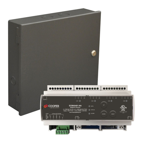
CSC354CPR is a 4-way sounder circuit controller with an
internal power supply and battery back-up. The CSC354CPR
sits on the addressable loop of the CIE and takes one
address, which is assigned by the panel during the
auto-learn cycle (see CIE installation manual for more
details). The loop interface has integral short circuit
isolators.
The internal power supply handles the voltage and current
demands of the unit (including the sounder circuits) and
self-monitors for Mains failure, Battery fault, Battery
Impedance fault and Charger fault. Each of these fault
conditions are indicated on the unit by the Fault LED and
a buzzer. The controller will also send the fault status to
the CIE via the loop protocol. The internal battery back-up
provides up to 30 hours stand-by with a 30 minute
alarm and is kept charged up by the PSU. When there is
power present (battery or mains) the Power LED will be
illuminated.
The sounder circuits allow for conventional sounders,
beacons and/or sounder/beacons to be fitted to the unit.
All sounder circuits are monitored for open and short
circuit conditions which are indicated on the unit by the
Fault LED and a buzzer (additional LEDs are provided
inside the enclosure to identify which sounder circuit is in
fault). The controller will also send the fault status to the CIE
via the loop protocol. The last device on each circuit must
be terminated with the end-of-line resistors provided to
facilitate the fault monitoring.
The sounder circuits can be activated by either shorting
the Class Change input or by command from the CIE via
the loop protocol, which result in 24VDC being supplied to
the sounder circuits. The Fire LED will only illuminate when
the sounders have been activated by command from the
CIE. When the class change is shorted and the system is
not in the Fire condition then the sounder circuits can be
deactivated by removing the short. When the system is
in the Fire condition then the sounder circuits can only be
deactivated by command from the CIE.
4. Funktionsbeschreibung
Am CSC354CPR stehen 4 überwachte Ansteueraus-
gänge für konventionelle Signalgeber zur Verfügung,
die Leitungsüberwachung erfolgt im Gegenpolprinzip
mittels Stromimpuls 24V/35mA. Jeder Ausgang darf
bei Ansteuerung mit max. 800mA belastet werden und
verfügt über eine elektronische PTC-Sicherung von 1,1A.
Die Gesamtlast aller 4 Ausgänge darf jedoch 1,6A nicht
überschreiten.
Das CSC354CPR verfügt über ein Netzteil ZPCB2209CPD,
dies stellt die Energieversorgung der Signalgeber im
Ansteuerungsfall zur Verfügung. Weiterhin werden im Gerät
2 Akkus 12V/4Ah eingebaut und vom NT überwacht und
geladen.
Die Signalübertragung auf der Ringleitung wird von der
BMZ aus gesteuert und mit Energie versorgt. Auch
nach Ausfall beider Spannungsquellen im CSC354CPR
kann weiterhin mit der BMZ kommuniziert werden.
Das Netzteil generiert die Störmeldungen Netzausfall,
Ladestörung und Akkustörung. Diese werden an die BMZ als
Sammelstörmeldung übermittelt „Stö. Netzteil Analogwert
160“. Werden die Ansteuersignale für Ausgang 1-4 über den
Ring geschickt, steuert das CSC345 die entsprechenden
Relais an. Zusätzlich wird die Spannung der Ringleitung
überwacht. Wird der Ring spannungslos, bevor das
Ansteuersignal zurückgenommen wurde, bleiben die
Ausgänge aktiv, um eine Alarmierung gemäß MLAR/LAR
sicherstellen zu können. Setzt der Ring das Ansteuersignal
Ausgang 1-4 zurück durch Aus Akustik, Abschaltung der
Signalgeber via FBF oder BMZ Reset, folgen die Ausgänge
entsprechend.
www.acornfiresecurity.com
www.acornfiresecurity.com
