S225-10-10
1-4
Procedure A: One Bypass Switch and
Two Disconnect Switches
1. Verify from regulator nameplate that control circuit
is connected for proper regulated system voltage.
2. Set power switch to OFF and control switch to OFF.
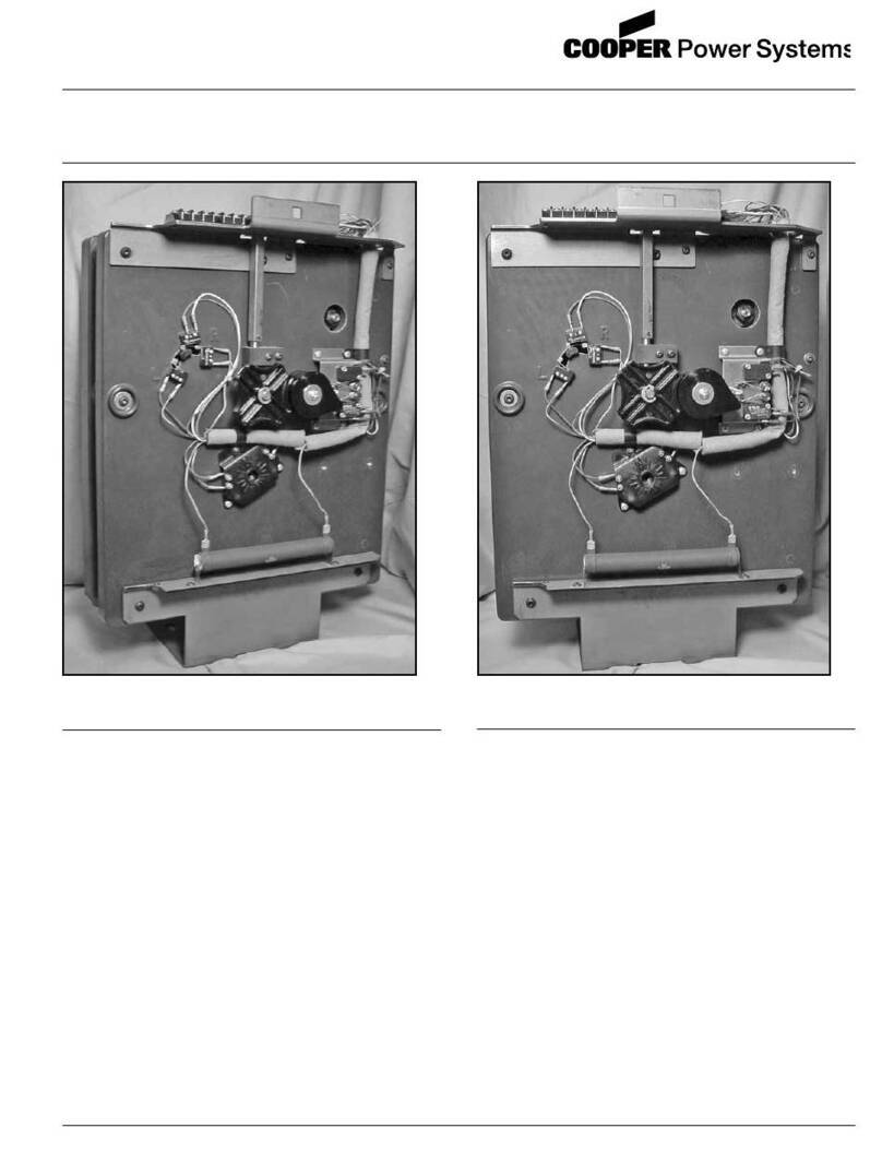
3. Knife switches on back panel should be set with V1
(potential switch) (and V6if present) closed (pushed
in), and C (CT shorting switch) open (pulled out).
See Figure 1-6.
4. Close source-load (SL) disconnect switch if
available.
5. Close source (S) disconnect switch.
6. Set power switch to INTERNAL and control switch
to MANUAL.
7. Lift raise-lower switch to operate tap changer two
or three steps, then depress raise-lower switch
to return tap changer to the neutral position.
(These steps verify that the mechanism is
functional.) When on neutral, neutral light will
glow continuously and position indicator will
point to zero.
8. With regulator in neutral position, set control switch
to OFF, set power switch to OFF, open V1knife
switch (and V6if present), and remove 6 A motor
fuse.
9. Close load (L) disconnect switch.
10. Open bypass switch. The regulator is now
energized.
11. Replace 6 A motor fuse, close V1knife switch and
set power switch to INTERNAL.
12. Go to Setting the Control for Service, following.
Procedure B: Regulator Bypass-
Disconnect Switch
1. Verify from regulator nameplate that control circuit
is connected for proper regulated system voltage.
2. Set control switch to MANUAL and power switch to
EXTERNAL.
3. Knife switches on back panel should be set with V1
(potential switch) (and V6if present) open (pulled
out), and C (CT shorting switch) closed (pushed in).
See Figure 1-6.
4. Apply 120 V (or other voltage as indicated by the
decal) to external source terminals, if available. If
not, proceed to Step 7, below.
5. Lift raise-lower switch to operate tap changer two or
three steps, then depress raise-lower switch to
return tap changer to neutral position. (These steps
verify that the mechanism is functional.) When on
neutral, neutral light will glow continuously and
position indicator will point to zero.
6. Remove the voltage from external source terminals.
7. With regulator in the neutral position, set control
switch to OFF, set power switch to OFF, and
remove 6 A motor fuse.
8. Close source-load (SL) disconnect switch. (Delta
applications only.)
9. Close regulator bypass-disconnect switch. The
regulator is now energized.
10. Replace 6 A motor fuse, close V1knife switch (and
V6if present), open C knife switch, and set power
switch to INTERNAL.
11. Go to Setting the Control for Service, following.
Setting the Control for Service
There are more than 50 parameters on the control which
are user-selectable. Many of these values pertain to the
operation of the advanced features that are not needed
for normal regulator operations. A full detailed
description of each of the features is given in the Control
Advanced Features section, along with set-up
instructions.
The control must be energized to perform the
programming. This can be accomplished by applying
120 V (or other voltage as indicated by the decal) to the
external source terminals and placing the power switch
in the external position. Alternately, the regulator may be
energized at line potential, and the power switch placed
in the internal position. When power is applied to the
control, all segments of the display will light, followed by
a PASS indication. If the FAIL message is encountered,
see Diagnostics, on page 2-5.
Accessing the Control
Before gaining access to change the control settings, the
proper security level must be activated. This is
accomplished by entering a security code at the
Function Code 99 location. Depress the following
keys on the keypad:
FUNCTION, 99, ENTER
12121, ENTER
The proper level of security to change operational
settings has now been activated.
All programming of the control is done through the
keypad or communication ports.
For quick set-up of Cooper Power Systems regulators,
see Table 1-1, page 1-5. For complete set-up, see
Table1-2, page 1-6 for a detailed checklist for control
programming. The only two parameters this checklist
does not address are voltage and current calibration,
Function Codes 47 and 48.
