Creda SPA 200c User manual

16
IMPORTANT WARNINGS!
DONOT SWITCH THE APPLIANCE ON IF YOU SUSPECT IT OF BEING FROZEN.
WAIT UNTIL YOU ARE SURE IT HAS THAWED OUT.
DONOT OPERATE THE APPLIANCE IF WATER DISCHARGES FROM THE PRESSURE RELIEF
VALVE.MAINTENANCE IS REQUIREDBEFORE THE APPLIANCECAN BE SAFELY USED.
THIS APPLIANCE IS NOT INTENDEDFOR USE BY PERSONS (INCLUDINGCHILDREN AND
THE INFIRM) WITH REDUCEDPHYSICAL, SENSORYOR MENTAL CAPABILITIES,
OR LACKOFEXPERIENCE AND KNOWLEDGE,UNLESS THEY HAVE BEENGIVEN
SUPERVISION ORINSTRUCTION CONCERNINGUSE OF THE APPLIANCE
BY APERSONRESPONSIBLE FOR THEIR SAFETY.
CHILDRENSHOULD BE SUPERVISED TOENSURE THAT THEY
DO NOT PLAY WITH THE APPLIANCE.
1. Ensure the electricity and water are turned on to the unit.
2. Press the start / stop button “B”.
This willturn the shower on, the water will flow and the
neon indicator lightwill illuminate. Itisrecommended that
you do notwholly enter the waterflow during this period.
3. Knob “A” controls the power selection.
Select“High”,“Medium (Med)”or “Cold”
The “smallbar” indicates knob setting.
4. If the water is not at your desired showering
temperature, turn knob “C” asmallamount until
you reach the desired showering temperature.
Turn clockwise for cooler or Turn anti-clockwise for warmer.
5. When you havefinished showering, press the start / stop button “B” again.
The water will stop flowing and the neon indicator willgo out.
10.5kWModelsOnly-Waterwill continuetoflow forapproximately 7 seconds beforeswitchingoff.
6. Switch offthe electricitysupply at the ceiling switch or local isolator.
Notes
•Wait 20 seconds forthe temperature to stabilise after each adjustment.
•The neon indicator light illuminates when the heaters are on and,if the shower has
been recently used, it may take up to 20 seconds to come on
.
During this time the water may go from very hotto cold before stabilising.
•The position of knob “C” will be approximately the same each time the shower is
used,varying onlywith incoming water temperature or pressure changes
(e.g. you will only need to change from summer towinter).
•During normal operation, if an overheated water temperature is sensed then the
heater will switch off and the neonindicator light will go out.
Water willcontinue to flow and cool down before the heater switches back on again.
We offeratechnical advisory service on thetelephone to installers and
othercustomerswith problemsin the field. RING 08443727766 (UKONLY)
(A3) Leaflet No. 567-2151-61b
HOWTOUSE YOUR SPA200C SHOWER (SUMMARY)
IMPORTANT:
This bookletshould be left with theuser
afterinstallation and demonstration
CREDA SPA200C RANGE
ELECTRICSHOWER
InstallationandUser Guide

2
Section
Introduction
.. .. . . . . . . .. . . . .. . . . .. .. ... .. ... .. .. ... .. ... .
Important Safety Information . .. .. .. .. .. . . . .. . . . .. . . . .. ... .. ..
Howto install your SPA200C Shower . . . .. ... .. ... .. ... .. .. ... .. .
Cold Water Inlet Pipe Configuration. .. .. .. . . . .. . . . .. . . . . . .. . . . ..
Assemblyof Accessories . . .. .. ... .. . .. .. ... .. ... .. .. ... .. ... .
Howto use your SPA200C Shower (Detailed) . . . . .. .. . . . .. . . . . . . . . .
Howto maintainyour SPA200C Shower . . ... .. ... .. . ... .. .. ... .. .
Additional Accessories and CommonParts .. ... .. ... ... . . . .. ... .. .
What to do if things gowrong (1)SelfHelp . . . . . . . . . . .. . . . .. .. . .. .
Creda After Sales Service . . .. .. ... . . . . . . .. . . . .. . . . .. .. ... .. ..
What to do if things gowrong (2) Professional Service . .. ... .. . . . .. ..
Howyour SPA200C Shower Works . . . .. .. .. ... .. ... .. ... .. ... .. .
Guarantee and Contact Details . .. .. . . . . . . .. . . . .. . .. .. ... .. ... .
Howto use your SPA200C Shower (Summary) ... . ... ... ... .. ... .. .
Page
3
3
4
6
9
10
11
11
12
12
13
14
15
16
CONTENTS
15
Full details of termsand conditions areavailable on request from:-
APPLIEDENERGYPRODUCTS LIMITED
MORLEY WAY, PETERBOROUGH PE2 9JJ
TEL: +44 (0) 844 372 7761
FAX: +44 (0) 844 372 7762
Website: www.creda-showers.co.uk
GUARANTEE ANDCONTACT DETAILS

14
1. Water isheatedinstantaneously as it flows
over the heating elements in the copper
cylinder (Diagram 8).
2. The heaters are onlyswitched on when
sufficientwaterisflowing.
Thisis done automaticallywith a switch
which works on water pressure and is
indicated by the neon indicator illuminating.
3. The wateris turnedon and offby the
solenoid valve (and Timer PCB on 10.5kW
models) built into the shower.
Thisis switched on when button “B”is
pressed.
4. The flow of water is automatically held at
the levelset by the user even though the
supply pressure may vary (see “Effect of
Other Water Devices on IncomingWater
Supply”).
5. Ifthe water supplyfalls below a set limit,
the pressure switch willoperate and switch off the power to the elements. This isindicated by
neon indicator going out (see “Effect ofOther Water Devices on Incoming Water Supply”).
6. As a furthersafeguard,a thermal cut-out switches the power off if the water temperature
climbs above the set limit.
Thiscut-out, which gives an audible click,may also operate due to residualheat when the shower
isswitched off. It willreset itself ifwaterisrun through the showerfor 10 to 20 seconds.
7. The pressure reliefdeviceis to safeguard against abnormal pressure conditions,and provides a
levelof appliance protection should an excessive build ofpressure occur withinthe shower.
Effect of Seasonal Incoming Water Temperature Changes
The required watertemperature isachieved by adjusting the rate ofwaterflow.
Diagram 9 shows the principle involved inrelating temperature riseto flow rate.
The higher the water rate the lower the temperature and viceversa.
The temperature of the watersupplied from the mains can vary considerably
throughout the yearfrom5 to 20°C.
This meansthat in the winter,flow rate will be less than in the summer to
achieve thesame outlet t
emperature.
In summer the “Medium(Med)” power setting maygive adequate hotwater.
In some winter conditions,it may be necessary to select the innerorouter spray pattern onlyof
your showerhandset. Thiswill ensurecorrect operation of the shower with a slightly lower flow rate.
Effect of Other Water Devices on Incoming Water Supply
Your shower is designed to stabilise temperature changes caused by water pressure
fluctuations. These can result fromtoiletsbeing flushedor taps being turned on and off.
When thishappens your showering temperature will be held within a controlled band,provided that
the minimumpressure required bythe shower is maintained.
Your shower requires aminimum running
pressure of 69kPa (0.7 bar,10 psi).
At pressures above 69kPa (0.7 bar, 10 psi)it willminimise temperaturefluctuationsas detailed
above. Ifthewater pressure fallsbelow 69kPa (0.7 bar, 10 psi) itislikely that the pressure switch
will turn offthe power to the heating elements,resulting inacold shower.
HOWYOUR SPA200C SHOWER WORKS
3
INTRODUCTION
If you experience any difficulty with the installation or operation of your new
shower, then please refer to the “What to do if things go wrong” section in this
manualbefore contacting us.
Thank you for purchasing a quality Creda SPA200C Shower manufacturedin England.
To enjoy yournew shower atits best,please take time to read this manual thoroughly to
familiarise yourself with all instructions, BEFORE beginning installation.
Having done so, keep this manual handy for future reference.
Your shower is designed to stabilise temperature changescaused by waterpressure fluctua
tions.
These canresultfrom toiletsbeing flushed or taps being turned on and off.
When thishappens your showering temperature will be held within a controlled band,provided that
the minimumpressure required by the shower is maintained (see “Effect ofOtherWater Devices”).
1. Your shower has been designed for convenience, economy and safety of use, provided that it is
installed,used and maintained in good working order and in accordance with our instructionsand
recommendations.
2. All wiring and installation must be supervised by a suitably qualified person.
3. THISAPPLIANCE MUSTBE EARTHED.
4. The installation mustbein accordance with the current edition of BS.7671 (the “IEE Wiring
Regulations”) and “Part P”ofthe “Building Regulations” inforce at the time ofinstallation.
Installations outside of England and Wales must also conform to any local regulations ineffect.
This appliance is intended tobe permanently connected to the fixedelectrical wiring ofthe mains
supplywith itsown dedicated supply.
5. This appliance must NOT be fittedwhere it may be subjected to freezing conditions.
6. DO NOT switchthe appliance on if you suspect it ofbeing frozen.
Wait untilyou are sure it has thawed out.
7. DO NOT fitany sort oftap orcontrol on the appliance outlet. The appliance isdesigned to have
an open outlet and should onlybe used with “Creda” recommended fittings.
8. Take care toavoid restricting the outlet of the pressure relief device.
Ifwater is discharged fromthepressure reliefdevice, maintenance will be required before the
appliance can be safely used.
9. Isolate the mainselectrical and water supply before removing the frontcoverofthe appliance.
IMPORTANTSAFETYINFORMATION

4
WARNING: ALLWIRING AND INSTALLATION MUST BE
SUPERVISEDBYASUITABLY QUALIFIED PERSON.
WARNING: DO NOT INSTALL THIS SHOWER WHEREITMAY BE
SUBJECTED TO FREEZING CONDITIONS
We recommend that the installation is done in the following sequence.
a. Fixing the shower tothe wall b. Plumbing c. Electricalconnections
a. FIXING THE SHOWER TOTHE WALL
1. Position the riser rail at a convenient height for majority ofusers as
detailed in Diagram 1 and mark itsposition.
2. Position the heatersothat the top of the unit is horizontaland level
with, or a maximum of 0.6 metres (2ft) below the topofthe
riser rail. Choose a flat piece ofwall to avoid the possibility of
distorting the backplate,as this may make the frontcover apoor fit.
3. Adjust theposition toget themost convenient arrangement taking
the following into account.
•The heatermust notbe mounted in the direct spray from the handset.
•The handset must not be ableto come into contactwith used water in the cubicle,bath or
basin. Ifit can, then a vacuum breaker mustbe fitted (availablefrom us ifrequired).
4. Fix the riserrail with screws provided.
The fixing holes at the base ofthe brackets willbe disclosed by removing the plastic fronts.
See Diagram 5 and instructions supplied with accessories forfurther details.
5. If you have not yet done so, remove the front cover assembly by undoing the retaining screws at
the topand bottom ofthe unit and lifting the cover off.
6. Your shower unit notonly accepts services from the top, bottom or rear.
It also accepts services from the leftorright hand side ofthe unit.
Decide the position of
the electricalcable into the unit.
If top entryis chosen, cut away the wallsin the backplate as shown in Diagram 2a.
If bottomentry is chosen, cut away
the wallsin the detachablebotto
m
section as shown in Diagram 2b.
The detachable bottom section is
securedtothe backplate by 2 screws.
7. Decidethe position of entry ofthe
cold water pipe into the unit.
Iftop entryis chosen,
cut away the backplateas shown in
Diagram 2a.
If bottomentry is chosen, cut away the
wallsin the detachablebottomsection
as shown inDiagram 2b.
If rear, please read the section on plumbing.
To aid installation,you may find it convenient to move the flexiblepressurerelief valve outlet
assemblyby removing the two securing screws.
If you do,please ensure that they are fullytightened on re-assembly(see Diagram 2b).
HOWTOINSTALL YOUR SPA200C SHOWER
13
WHAT TO DO IF THINGS GO WRONG (2)
PROFESSIONAL SERVICE
If the previous “Self Help” checks fail to restore the performance,you shouldseek professionalhelp.
The person who installed the shower is probablythe bestone to investigate andcorrect itand is
certainly the person tocontact if you have had a problem in the guarantee period.
The following additional checklistis provided for the benefit ofthe qualified service person.
WARNING:
SWITCHOFF THE ELECTRICITYATTHE LOCAL ISOLATOR
BEFORE REMOVING THE COVER TO MAKECHECKS
WatertooHOT Waterflowrestrictedby blockage in filterofsolenoidvalve.
Replace the solenoidvalve.
WatertooCOLD Check circuitthrough thermal cut-out.
Check circuitthrough microswitches on the pressureswitch & power selector.
Check eachelement circuit (andphasedshut-downrelayon 10.5kWmodel).
Check tightnessofelectrical connections.
No control over
water flow Check control knobiscorrectly engagedonto the stabiliser valve drive gear.
Undo headworksof stabiliser valve.
Check stabiliserisin place andremove any debrisin valvethen re-assemble.
Waterdischarges
from pressure
reliefvalve
Check for cause ofhigh pressureandremove it.
Blockage on outlete.g. blockedshowerhandset.
Replace the pressurereliefdisc(not coveredbyguarantee).
Waterdoesnot
flowwhen button
“B”ispressed.
Check circuitthroughsolenoidcoil (andtimerPCB on 10.5kW model).
Check circuitthroughpushbuttonswitch. If items are defectivethen replace.
Power supplynot reaching shower.

12
CREDA AFTER SALES SERVICE
SELFHELP
If the showeris not working satisfactorily,make the following checks before calling outthe installer
.
Any one oftheseadjustmentscould restore the performance.
Theshower cycles
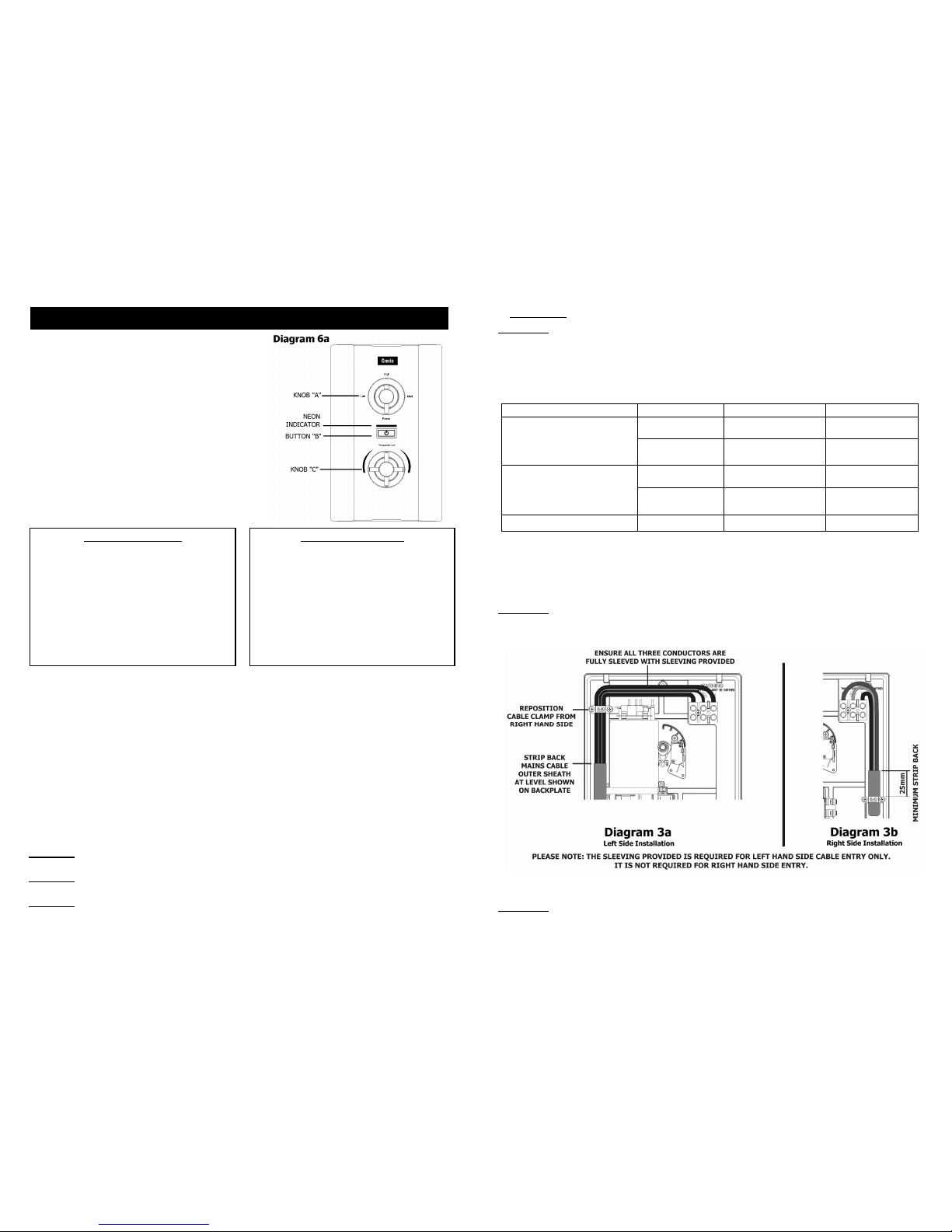
from HOTtoCOLD The shower temperature isset toohotcausingthe thermal cut-out (safety
device)tooperate.
Turn knob“C”clockwise
toincrease water flow.
Slowlyincreasethe watertemperature by turning knob“C” anti-clockwise until a
comfortable showeringtemperature hasbeenreached.
You MUSTWAIT approximately20 secondsforeach adjustment toaffect the
watertemperature.
“Medium (Med)” settingmay needtobe selected.
WatertooHOT Increasewater flowbyadjustingknob “C” clockwise.
“Medium (Med)” settingmay needtobe selected.
Increasepressure towatersupplye.g.fullyopen service valve orstopcock.
Check hoseisnot kinked restrictingthe water flow andclean handset.
WatertooCOLD Check powerisonbyneonindicator beingilluminated.
Decrease waterflowbyadjustingknob“C” anti-clockwise.
“High” settingmayneed tobe selected.
Select inner orouter only handsetspray pattern.
Spray pattern poor Clean the showerhandset.
Watertakeslonger
toheat up Thermal cut-out hasoperatedafterprevious use andtheneon indicator has
gone out (automaticallyresetswhen unitcoolsdown)
“High” settingmayneed tobe selected.
Watergoescold
whileusing
shower
Check neon indicatorisilluminated.
Check waterpressure has notfallen sofarasto letpressure switch cut out,
e.g. Anothertapdrawing wateroff.
Raiseposition of shower handset.
Broken parts Please contactoursparesdepartmenton 0844 3727750 (UK only).
Fittinginstructionsare providedwith most spares
Watercontinues to
flow when button
“B” pressed tostop
Thisisnormal for 10.5kW modelsonly(Othermodelscontact “AfterSales”)
The shower includesa shutdown feature thatmeansthe water will continue to
flowfor upto7 seconds after“ (stop)”hasbeen selected.
We offer a technicaladvisory service on the telephone to installers and othercustomers with
problems inthe field.
RING 0844372 7766 (UKONLY)
Some spare parts (see Page 11) can be supplied againstCreditor Debit cards.
RING 0844372 7750 (UKONLY)
Remember to quote the exact type ofshower, as written on the front ofthe showerand on this
leaflet.
The modeland serial number arelocated on the bottom face ofthe shower.
Make a note of those numbershere, and be sure to quote them ifyou callfor advice.
Model Number: 53-67___ __ __/ Serial Number: __ __ ___ _ _ __
Note: You may be charged for aservice call if you do nothave the serialnumber.
WHAT TO DO IF THINGS GO WRONG (1)
5
8. Yourshowerisprovidedwith3 fixing
positionsin the backplate (seeDiagram 8).
The top-fixinghole is a “key-hole” slot,
andshouldbe markedand drilledfirst.
Tighten topscrew with headprotruding
about 10mm from thewall andhookthe
backplate overthe screw head.
Thisallowsforcorrectand accurate
alignment of yourshower before marking
andfixingthe bottompositions.
You maynot wish totighten upboth screws at this
stage asthe holesareelongatedtoallowfor adjustment after otherconnectionshave taken place.
b. PLUMBING (For yourconveniencea coldwater inletconfiguration diagramisshown on page 6)
WARNING: ENSURE THAT THE MAINS WATER SUPPLY MEETS THE REQUIREMENTS BELOW
BEFORE CONTINUINGWITH INSTALLATION.
The heater must be connectedtothe mains cold water supply.
Thismust have a minimumrunningpressure of69kPa (0.7bar, 10 psi)
anda maximum pressure of690kPa(7.0 bar, 100 psi).
WARNING: BEFORE CONNECTINGTHE PIPE WORK TO THESHOWER,
ENSURE THAT THE PIPE WORK IS FULLY FLUSHED OUT.
1. Unscrew the “RedCap”from the showeroutletpipe anddiscard it in a suitable manner.
It has been usedtoseal the showerduringtransit, and is nolongerrequired.
2. It is recommendedthat a WRAS (Water RegulationsAdvisory Scheme) listedisolatingvalveisfitted
tothe incomingmainscoldwaterbefore the shower unit. Thiswill allow the unit tobe serviced or
exchangedwithouthavingtoturn offthe mains water at the waterstop valve.
3. The heater can be fedfrom a header tankprovided thishasa minimum headof7 metres (23ft).
4.
The coldwaterinlet connectionsuppliedis a plain Ø15mm straightshank/shaft.
Thisconnectorwill accept eithera Ø15mmcompressionelbowor a Ø15mm“push-onelbow”.
Ø15mm copper, stainless steelor suitable plasticpipeshould beused.
Foryour convenience,acold waterinletconfiguration diagramisshownonpage 6
.
Ifrearentryisrequired, treatastopentrywithan additional “Yorkshire”elbow (solderedtype) for
fitting intotherearchannel.
Toaid installation, youmayfind itconvenienttomovetheflexiblepressurereliefvalveoutlet
assemblybyremoving thetwosecuring screws (SeeDiagram2b).
Inmultipleinstallations,correctpipeworksizes shouldbecalculatedtomaintain adequateflowto
eachshower.
5. It is permissible to use a WRAS (WaterRegulationsAdvisory Scheme)approved sealant sparingly
whilstavoidingexcess findingits way intothe showeroperatingparts.
6. With isolating valve connected, flush the pipework through to remove any particles etc,
before makingthe final connectiontothe shower.
Blockage in the waterways(particularly the handset andsolenoidvalve)will prevent the heater
workingproperly. Note: You maybe chargedfor a service call ifitisdue toincorrect installation.
7. The showerisdesignedtohavean open outletandshouldonly be used with “Creda” recommended
fittings.
Do not connect thehandset until afterthe front coveranddetachable bottom section are fitted.
WARNING: DO NOT FIT A TAP ON THE SHOWER OUTLET.
WARNING: TAKE CARE TO AVOID RESTRICTING THE OUTLET OF THE
PRESSURE RELIEF VALVE.

6
Please note that standard compression fittings are shown.
Push-Fit connections or a combination of the two are also suitable.
To aid installation,you may find it convenient tomove the flexiblepressure relief valve outlet
assembly by removing the two securing screws.
If you do,please ensure that they are fullytightened on re-
assembly(see Diagram 2b).
COLD WATER INLET PIPE CONFIGURATION
11
HOWTO MAINTAIN YOUR SPA200C SHOWER
Itis recommended that the shower unit and hoseetc. becleaned usinga softclothand thatthe use of
abrasive or solvent based cleaning fluid be avoided,especially on any platedfinishes.
We recommend that before anycleaning, the isolating switchbe turned off, thus avoiding accidentally
switching on the shower.
WARNING: YOU MUST REGULARLY INSPECTTHE SHOWER HOSE FOR WEAR AND DAMAGE.
REPLACE IF NECESSARY, OR EVERY TWO YEARS, WITH AN APPROVEDPART.
WARNING: IN ORDER TO MAINTAINTHE PERFORMANCE OF YOUR SHOWER,
YOUMUSTREGULARLY CLEAN THESHOWER HANDSET.
All water contains particles of lime-scale, which buildup in the showerhandsetand unitreducingthe
performance.
Itis therefore importanttoclean the shower handset by simply rubbing the rubber nozzles,or soaking in
proprietarylime-scale remover and rinsing thoroughly before use (actual shower handsetnot necessarily
shown).
NOTE: After use itisnormal for some water todripfrom the shower handset for a
few moments.This inhibits lime-scale build-upover prolonged use.
Please Note:- Thefitting of Spare Parts must be supervisedby asuitablyqualifiedperson.
White 2.0m ShowerHose CatNo. 83792578 Front Cover Assy CatNo. 93550811
Chrome 1.25m Shower Hose CatNo. 93797641 Thermal Cut-Out50/88°C CatNo. 93597871
WRAS Listed Water PRV Washer CatNo. 93795817
Isolating Valve CatNo. 93792452 Cylinder “O”-Ring CatNo. 93795809
Chrome Standard Accs CatNo. 83595317 Solenoid Valve CatNo. 93590355
Chrome Multi-Mode Accs CatNo. 83595318 Backplate Lower Section CatNo. 93590356
Chrome Premium Accs CatNo. 83595319 PRV OutletBody Assy CatNo. 93590357
Chrome CurvedAccessories CatNo. 83595320 Flexible Outlet Pipe c/w Clip CatNo. 93590358
Curtain and Rail Pack CatNo. 83792812 TankClip CatNo. 93590715
Curtain and Rail Packwith Handset CatNo. 93597862
Non-Slip Mat CatNo. 83792811 HeightAdjuster CatNo. 93597861
ADDITIONAL ACCESSORIESCOMMON SPAREPARTS
Additional accessoriesand spareparts can besuppliedagainstany
Credit or Debit cards from Creda Sales Hotline 0844 372 7750

10
IF WATER ISTOO COLD
Turn knob “C” anti-clockwise “1/8”ofaturn
and continue turning anti-clockwiseuntil youget
the water temperature ofyour liking.
Wait 20 seconds aftereach adjustment for the
water temperature tostabilise.
The finaladjustmentmaybe in any positon.
If after turning fullyanti-clockwisewater is still
toocold,setshower pattern onshower handsetto
outer or innerpattern only.
IF WATER ISTOO HOT
Turn knob “C” clockwise “1/8” of a turn and
continue turningclockwise until yougetthe water
temperature of your liking.
Wait 20 seconds after eachadjustmentfor the
water temperature tostabilise.
The finaladjustmentmay be in any position.
If after turning fully clockwise,wateris stilltoo
hot, adjust knob“A” to “Medium (Med)”setting
and re-adjustasabove.
Water flow willbe reduced on thissetting.
1. Ensure the electricity and water are turnedon tothe unit.
2. Your shower has2control knobs(see Diagram 6a).
Knob“A” controls the 3 power settings.
The mostpopular is“High”.
There arealso options fora “Medium (Med)”
or “Cold” shower (see notes 7 and 8).
Knob “C”controls the temperature of the water.
Forthis example turn knob “A” to “High”
and set knob “C”to the “mid-position”as shown in
Diagram6a.
3. Press button “B”.
The water willflow and the neon indicator will illuminate.
4. Allowabout20 seconds for the temperature of thewater to stabilise.
Itis recommended that you do not whollye
nterthe watersprayduring
thisperiod,especially if the shower hasjustbeen used.
5. Once a temperaturesetting toyour liking hasbeen achieved, knob “C”will rarely needadjusting.
You musthowever take into account required adjustmentsfor variations of incoming mains water
temperature between summer andwinter (see “Effectof Seasonal IncomingWater Temperature
Changes” see page 13).
6. When you have finished showering, pressbutton “B” only.
You have no needto adjust knobs“Aor C”.
The water willstop flowing and the neon indicator will go out.
10.5kW Variants Only - Waterwill continue toflow forapproximately 7 secondsbeforeswitchingoff.
Switch off the electricity at the ceiling switch or local isolator.
7. The “Medium (Med)” setting of knob “A”reduces the power used by the shower givinga cooler shower or
the option of reduced water flow.
This option is mainly usedfor summer usageand if thisisused then knob “C”mustbe re-adjusted.
8. The “Cold”setting of knob “A”will supply water without any heating.
9. Your shower is designed to stabilise temperature changescausedbywater pressure fluctuations
(see “Effect of Other Water Devices on Incoming Water Supply”see page 13).
WARNING: DONOT SWITCH THE SHOWER ON IF YOU SUSPECT ITOFBEING FROZEN.
WAIT UNTIL YOUARESUREIT HAS THAWED OUT.
WARNING: DONOT OPERATE THE SHOWER IF WATER IS DISCHARGEDFROMTHE PRESSURE RELIEF
VALVE. MAINTENANCEIS REQUIRED BEFORETHESHOWERCAN BE USED.
WARNING: CONSIDERATION SHOULD BE GIVEN TO SUPERVISINGTHEYOUNG, ELDERLY AND THE
INFIRM WHILST THEY USE THIS SHOWER.
HOWTOUSE YOUR SPA200C SHOWER (DETAILED)
7
c) ELECTRICAL
WARNING: THIS SHOWER MUST BE EARTHED.
The electrical installation mustbe in accordance withthe current BS.7671 (IEEWiringRegulations)
and“Part P” ofthe BuildingRegulationsand/orlocal regulations.
1. The shower unit isdesignedfora single phase AC electrical supply.
Please checkthe ratingplateon theunit toseewhatdetailsapplytoyour shower.
AS A GUIDEONLY (*Onlyappliesif external earth impedance isless than 0.35 Ohms)
Rating Cable Sizes
Fuse / MCB
Cable Length
6.0mm²
10.0mm² 40A Type B MCB 27m Max.
45m Max.
8.5 / 7.8kW240 / 230V 6.0mm²
10.0mm² 45A BS.1361 fuse 12mMax.*
21mMax.*
6.0mm²
10.0mm² 40A Type B MCB 27m Max.
45m Max.
9.5 / 8.7kW240 / 230V 6.0mm²
10.0mm² 45A BS.1361 fuse 12mMax.*
21mMax.*
10.5 / 9.6kW 240 / 230V 10.0mm² 45A BS.1361 fuse 12mMax.*
Remember toupgrade the cable ifit runsin thermal insulation in a loft, orfora longer distance.
2. A meansfor disconnection in all polesmust be incorporatedin the fixedwiringin accordance with
the wiringrules. Werecommenda ceilingswitch mountedin a convenientposition.
3. Ifyou have decidedtoconnect the cable on the left handside thenpleaseremoveandusethe
cable clampthat wasprovidedalongthe rightside (see Diagram 3).
WARNING: IFLEFT HAND SIDE CABLE ENTRY IS USED, THE MAINS CABLE OUTER SHEATH
MUST BE STRIPPED BACK TO THE LEVEL MARKEDONTHE BACKPLATE,ANDALL
THREE CONDUCTORS MUST BE FULLY SLEEVED WITH THE SLEEVING PROVIDED
BETWEEN THEREAND THE TERMINAL BLOCK (SEE DIAGRAM3a).
4. Connect cable toterminal blockmakingsurethat all theretainingscrewsare VERY TIGHT and that
no cable insulation istrappedunderthe screws.
WARNING: FAILURETO COMPLY WITH THESE INSTRUCTIONS COULDRESULT IN FAILURE
OF THE TERMINAL BLOCK.

8
5. Re-fit the detachable bottomsection with the two screws if it wasremoved.
6. Re-Fitthe front cover (see Diagram 4), andsecure byreplacingthetop andbottomfasteningscrews.
a. Ensure the top control knob isalignedtothe“High” positionasshown (Diagram 4a).
b. Ensure the control knob isaligned asshown (Diagram4b).
c. Inthe main bodyof theshower ensurethe “raisedpip”of the “camshaft”, positionedto accept the
top control knob, is setto 12 o’clock(Diagram4a).
d. Inthe main bodyof the showerensurethe “bottomgearwheel”, positionedtoaccept the bottom
control knobisturnedfullyanti-clockwiseasshown (Diagram4b).
e. Checkthat the top control knob hasbeen correctly alignedby ensuring thatall three settings can
be selected.
f. Checkthat the bottom control knob hasbeen correctlyalignedbyturningclockwiseandensuring
that the knob turnsapproximately one full turn andwhenturnedbackfully anti-clockwise returns
to the original point.
7. Fitthe shower hose, and operate the showerfirst withoutthe handset to flush out particles,
fit the handset andthen operatethe showerason page 10 or16and check:
a. Watergetstoa satisfactorytemperature andwaterflow can be adjustedby control knob “B”.
b. Powerselection operates in all 3 positions, giving a changein watertemperature.
c. Check again for leaks and thatthe holesin the showerhandset arenotblocked.
8. Demonstrate the showers operation to all users.
9
ASSEMBLYOF ACCESSORIES
Diagram 5 - Riser Railand Soap Dish Fitting Instructions
(Refer totheseparatefitting instructionsheet packedwith the accessoriesformore details)
1. Establish height ofriserrail tosuit userrequirements.
Thisshouldbe amaximumof 0.6metres(2ft)above the level of the heater, see (a)below.
2. Remove covers fromthe wall brackets(b).
3. Positionthe lowerbracket andmarkthe wall for the screwfixing(c).
Thendrill andplugthe wall andfixthe lowerbracket without the rail locationnotch.
4. Fit therail intothe lowerbracket.
Place theremaining bracket with the rail location notch on topof theriser rail, makingsurethat the
rail slot islocatedintothe notch.
Ensure thehole position isvertically alignedandmark the wall (d).
Remove the rail andbracket, then drill andplugthewall.
5. Assemble the heightadjuster(e).
6. Compressthe heightadjuster assemblyandslideonto the rail.
Fit thehoseretainingring andthen the soapdish on the bottomofthe rail (f).
Lock the soapdish intoposition bytighteningthe locknut.
7. Replacethe rail assemblyintothe lowerbracket.
Refitthe topbracket, ensuringthe slotin the rail islocatedintothebracketnotch andfix tothewall.
Slidecoversontoboth brackets.
NOTE: The adjustableslidergripstheconical nut on the shower hose (g).
Table of contents
Other Creda Plumbing Product manuals

Creda
Creda Florida Spa User manual

Creda
Creda JETSPA CONTEMPORARY User manual

Creda
Creda 570 User manual

Creda
Creda BRISBANE 8.5 kW User manual

Creda
Creda AquaNoir User manual

Creda
Creda Shower SPA User manual

Creda
Creda PW E4ZC Manual

Creda
Creda Aquawave White User manual

Creda
Creda Aquathermo 53 series User manual

Creda
Creda Thermostatic Power Shower User manual