manuals.online logo
Brands
  1. Home
  2. •
  3. Brands
  4. •
  5. Creda
  6. •
  7. Plumbing Product
  8. •
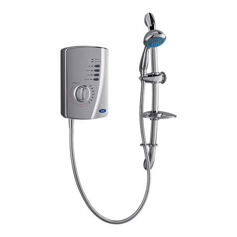
  9. Creda Florida Spa User manual

Creda Florida Spa User manual

8
(Leaflet No. 559.2323.61b)
Full details of terms and conditions are available on request from: -
APPLIED ENERGY PRODUCTS LIMITED
MORLEY WAY, PETERBOROUGHPE2 9JJ
TEL +44 (0) 844 372 7761 /FAX:+44 (0) 844 372 7762
Website: www.creda-showers.co.uk
We offer a technical advisoryservice onthe telephone to installers and other customers
with problems in thefield. RING 0844 372 7766 (UK ONLY)
SHOWER HANDBOOK
IMPORTANT:
This bookletshouldbeleft with the user
after installation and demonstration.
2
Contents
Information for the user Page
Howtouse yourCreda Shower . . . . . . . . .. . 2
Howyour Creda ShowerWorks . . . . . .. . .. .3
What to do if things go wrong . .. . . . . . . . . . 4
Howtomaintain yourCreda Shower . . . . . . 4
AdditionalAccessories / Spare Parts. . .. .. .7
Information for the installer
Fixing the Showerto the wall. . . . . .. . . . . . 5
Plumbing . .. . . . . . .. .. . . . . . . .. . . . . . . . . 6
Electrical .. . . .. .. . . . . . . .. . . . . . . . . . . .. 6
Guarantee . . . . . . ... . .. . . . .. .. . . . . . . . . 8
Thank youfor choosing a quality Creda productmanufactured in Peterborough, England
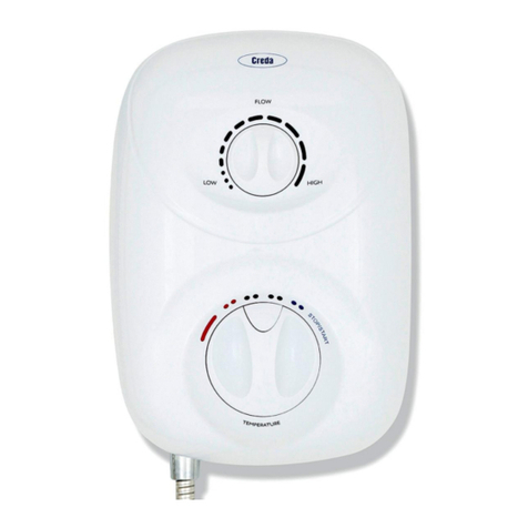
Howto use your Creda Shower
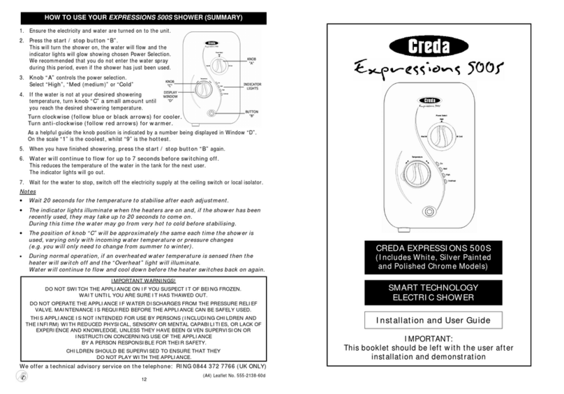
1. Ensure the electricityand water are turned on to the unit.
2. Your showerhas 3 powersettings selected by turning knob “A”.
The most popularis “FULL HEAT” indicated by “ ” and for your convenience thiscanbe obtained in2positions so
youarealways only one step awayfrommaximumpower.
There are also options for a“HALF HEAT” or “COLD” shower(see notes 8 and 9).
For this example turn knob “A” to“FULL HEAT” (either willdo) and set knob“C” to “6 o’clock” on thescale.
3. Press button“B”. Water will flow, 3 lights will illuminate to indicate that the selected powerrating is “FULL HEAT”.
4. Allow about 20 seconds forthe temperature of the water to stabilise. It is recommended that you do not wholly
enterthe water spray during thisperiod, even if the showerhas just been used.
5a. If the water is toohot, thenincrease the flow of waterby turning knob “C”clockwise to “7 o’clock” on the scale.
Wait20 seconds for the temperature of the waterto stabilise.
Repeat turning clockwise ifnecessaryuntil yougetthe water temperature of yourliking.
5b. If the water is too cold, turn knob “C” anti-clockwise to “5 o’clock” on the scale and continue as necessaryuntil
you get the watertemperature of your liking.The final adjustment maybe anywhere on the sc ale.
5c. Basically turning knob “C” anti-clockwise increases the watertemperature,
whilst turning clockwise decreases the water temperature.
6. Once a temperature setting to your liking has been achieved, knob “C” will rarely need adjusting,
eg: adjustfor variations of incoming mains watertemperaturebetween summerand winter.
7. When you have finished showering,push button “B” only.You have no needto adjust knobs “A” or “C”.
Switch off the electricityatthe ceiling switch or local isolator.
8. The “HALF HEAT ”setting of knob “A” reduces the power used by the shower giving a cooler showerorthe option
of reduced water flow. This option is mainly for summer usage andif this is used then knob “C”must be
re-adjusted. On this setting 2 lights willilluminate to indicate thatthe selected power rating is “HALF HEAT”
9. The “COLD” settingindicated by“ ” of knob “A” will supplywater without anyheating, and only1light will
illuminate to indicate this.
10. Your showeris designed to stabilise temperature changes caused bywater pressure fluctuations. These can
result fromtoilets being flushed or taps being turned on and off. When this happens your showering temperature will
be held within a controlled band, providedthatthe minimumpressure required bythe shower is maintained.
11. Your showerrequires a minimumoperating pressure of 69kPa (0.7 bar, 10 psi). At pressures above 69kPa
(0.7 bar, 10 psi) it will minimizes temperature fluctuations as detailed above in note 10. If the water pressure falls
below 69kPa (0.7 bar, 10 psi) it is likely that the pressure switch will turn off the powerto the h eating elements,
resulting in a cold shower. The 2 middle power indication lights willflicker and go out and the “OVERHEAT” light
may come on to indicate this has happened.
12. During normal operation ifan overheated watertemperature is sensed bythe showerthen the thermal cut-out will
switch offtheheating elements. The“OVERHEAT” light will illuminate to provide a visual indication that this has
taken place. Water will continue to flowand as the water temperature fallsthe heating elements will be turn ed back
on. Ifthe “OVERHEAT” light continues tocycle then turn knob “A” to the “HALF HEAT ” power setting (knob “C”
will need adjusting). If the showeris operatedafterit has recentlybeen used the “OVERHEAT”light mayilluminate
for a fewseconds. This indicates that there is still some hotwater left in the shower.
Either, wait a fewmoments for the light to go out or turn knob “C”clockwise.
13. Note that knob “C” IS NOT ATAP and does not turn the wateroff.
WARNING:DO NOTSWITCH THE SHOWER ON IF YOU SUSPECTITOFBEING FROZEN.
WAIT UNTILYOU ARESURE IT HASTHAWEDOUT
7
4. WARNING:THIS APPLIANCE MUST BE EARTHED
5. Fit the cornersection back into the backplate
6. Fit the front coverbackinto position making sure the
knobs are aligned correctly with the flowvalve and
power selector(see diagram10).
Start by locating the “tang”around the recess for the
outletpipe, and then “roll” the front cover over the
knobs and onto the top of the backplate.
Secure the top and bottomfastening screws.
7. Operate the showerfirst without the handset to flush
out particles, fitthe handsetand then operate the
shower as on page 2 and check:
a. Thatthewater gets to a satisfactorytemperature.
b. Waterflow can be adjusted byknob “C”.
c. Power selection does give a change in water
temperature and power lights illuminate.
d. Check again for leaks
e. Thatthe holes in the spray plate arenot blocked
8. DEMONSTRATEOPERATIONTOUSER
Additional Accessories / Spare Parts
White 2 metre Shower Hose Catalogue No. 83-593529
1 metre RiserRail Catalogue No. 83-593530
Extended Shower Control Lever
(Interchangeable with Control Knob) Catalogue No. 83-590710
WRAS listed Water Isolating Valve Catalogue No. 93-792452
Curtain and Rail Pack Catalogue No. 83-792802
Curtain and Rail Pack with Non-Slip Mat Catalogue No. 83-792801
Spare1.25mlong Chrome Shower Hose Catalogue No. 93-797641
Spare parts/accessories can besupplied against any Credit or Debit cards from Sales Hotline 0844 372 7750
This appliance is not intended for use by persons (includingchildren and the infirm) with reduced physical,
sensory or mental capabilities, or lack of experienceandknowledge, unless they have been given supervision
or instruction concerning use of the appliance by a person responsible for their safety.
Children should be supervised toensurethat they do not play with the appliance.
6
b. Plumbing
The heatermust be connected to the mains cold water supply. This musthave a minimumrunning pressure of 69kPa
(0.7 bar, 10 psi) and amaximum pressure of 690kPa (7.0 bar, 100 psi).
Before connectingthe pipe work to the shower, ensure that pipe work is flushedout.
1. Itis recommended that a WRAS(WaterRegulations AdvisoryScheme) listed isolating valve is fitted to the incoming
mains cold waterbefore the shower unit.
This will allow theunit to be serviced or exchanged wi thout having to turn off the water at the waterstop valve.
2. The heatercan befedfrom a header tankprovided this has a minimumhead of 7 metres (23ft).
3. Ø15mmcopper or stainless steel pipe should be used.
To avoid cross threading, DO NOT REMOVE the brass nutfromthe elbow when positioning the pipe.
Iftop entryisrequired, turn the elbow 180° into the required position.
Ifrear entry is required,treat as top entry with an additional“Yorkshire”elbow (soldered type) for fitting into the rear
channel.
In multiple installations, correct pipe work sizes shouldbe calculated to maintain adequa teflow to each shower.
4. Itis permissible to use a WRAS(WaterRegulations AdvisoryScheme) approved sealant sparingly whilst avoiding
excess finding its way intothe shower operating parts.
5. With isolating valve connected, flush the pipe work throughto remove anyparticlesetc,before making the final
connection to the shower. Blockage in the water ways(particularlythe handset and solenoid valve) will prevent the
heater working properly. Note: You may be charged for a service callifit isdue to incorrect installation.
6. The showerisdesigned to have an open outlet andshould onlybeused with ”Creda” recommended fittings.
Donotconnect the handsetuntil after the showerfront cover and cornersection are fitted.
WARNING:DO NOTFIT A TAP
ONTHE SHOWER OUTLET.
TAKECARE TOAVOID RESTRICTING THE OUTLET OF THE PRESSURE RELIEF DEVICE
c) Electrical
The electrical installation must be inaccordance with the current BS.7671 (IEEWiring Regulations), and Part “P”of the
Building Regulations.
1. The showerisdesigned fora single phase AC electrical supply. Check the unit rating plate to see which applies.
(* Only applies if external earth impedance is less than 0.35 Ohms)
Rating CableSizes
Fuse /MCB
Cable Length
4.0mm²
6.0mm²
32A Type B MCB 21mMax.
35mMax.
7.2 /6.6kW 240 / 230V
.6.0mm²
10.0mm²
40A Type B MCB 27mMax.
45mMax.
6.0mm²
10.0mm²
40A Type B MCB 27mMax.
45mMax.
8.5 / 7.8kW 240 / 230V
and
9.5 / 8.7kW 240 / 230V 6.0mm²
10.0mm²
45A BS.1361 fuse 12mMax.*
21mMax.*
10.5 / 9.6kW 240 / 230V 10.0mm² 45A BS.1361 fuse 12mMax.*
Remember to upgrade the cable if it runs in thermal insulation in a loft, or for a longerdistance.
2. A means for disconnection in allpoles mustbe incorporated in the fixed wiring in accordance with the wiring rules.
We recommend a ceiling switch mountedin a convenient position.
3. Cutbackcable as in diagram9. Connectcable to terminalblock
making sure that all the retaining screws are VERY TIGHT and
that no cable insulation is trapped underthe screws.
3
Howyour Creda Shower Works
Yourshower is designedfor convenience, economy and safetyof use.
1. Waterisheated instantaneouslyas it flows over the heating elements in the copper cylinder(diagram2)
2. The required water temperature is achieved by adjusting the rate of water flow. Diagram3
shows the principle involved in relating temperature rise to flow rate.The higherthewater
rate the lower the temperature rise and vice versa. The temperature of the watersupplied
fromthe mains can varyconsiderablythroughouttheyear from5 to 20°C. This means
that in the winter, flow ratewill be less than in the summer to achieve the same outlet
temperature.In summerthe “HALFHEAT”power setting maygive adequate hot water.
3. The heaters are onlyswitched onwhen sufficientwateris flowing.
This is done automaticallywith a switch which works on waterpressure and is indicated by2 or 3 lights illuminating
depending on knob “A” power selection.
4. The water is turnedon andoff bythe solenoid valve built into the shower. This is switchedonbybutton “B ”.
5. The flowof water is automaticallyheld at thelevel set by the usereventhough the supplypressuremayvary
(See “Howto use your shower”note 10).
6. If the water supplyfalls belowa set limit, the pressureswitch will operate and switch offthe power to the elements.
This is indicated bythe middle power setting lights flickering and going out (see “How to use your shower”note 11).
7. As a further safeguard, a thermal cut-out switches the power offif the watertemperature climbs above the set limit
and the “OVERHEAT” light will come on.
This cut-out, which gives an audible click,mayalso operate due to residual heat when the shower is switched off.
It will reset itselfif water is run through the shower for 10 to 20 seconds, and the “OVERHEAT” lightwill go out.
8. The pressure relief device is to safeguard against abnormal pressure conditions, and provides a level ofappliance
protection should an excessive build up ofpressure occur within the shower.
INORDERTOMAINTAINTHE PERFORMANCEOFYOURSHOWER,
YOU MUST CLEAN THE SHOWERHEAD REGULARLY.
All water contains particles of lime-scale, which build up in theshowerhead and unit reducing the performance.
It is thereforeimportant to clean the showerhead by simply rubbing the rubber nozzles, or soaking in a proprietary
lime-scale removerand rinsing thoroughly before use.
NOTE: After use itis normal for some watertodrip fromthe showerhead for a few moments.
This inhibits lime-scale build-up overprolonged use.
4
What todo ifthings go wrong
SELF HELP
Ifthe shower is not working satisfactorily
, make the following checks before calling outthe contractor.
Any one of theseadjustments could restore theperformance.
a) Theshower cycles
from HOT to COLD The shower temperature is set too hot causing the thermal cut-out (safety device) to operate.
Turn the temperature knob fully clockwiseto increase the water fl
ow.
“HALF HEAT ” setting mayneed tobe selected.
Slowlyincrease the water temperature byturning knob anti-clockwise until a comfortable
showering temperaturehas been reached.
YouMUST WAIT approximately 20 seconds for eachadjustment to affect the water temperature.
b) Water too HOT Increase water flow byadjusting the temperaturecontrolclockwise.
Clean showerhead holes. Select outer or combination spraypattern.
Switch power to “HALF HEAT ” setting.
Increase pressure to water supply e.g. fully open service valve or stop cock.
Checkhose isnot kinkedrestricting the water flow.
c)Water too COLD Decrease water flow byadjusting the temperaturecontrol anti-clockwise.
Switch power to “FULL HEAT ” setting.
d) Spray pattern poor Clean showerhead and flush heater.
e) Water takeslonger
toheat up Thermal cut-out hasoperated after previous use (“OVERHEAT” light is on).
Will automaticallyreset when unit cools down.
Switch power to “FULL HEAT ” setting.
f) Water goes coldwhile
using shower Checkpower settinglights areon.
Checkwater pressure hasnot fallen so far as to let pressure switch cut out,
e.g. Another tap drawing water off.
Raise position of handset.
g) Broken parts Please contact our spares department on 0844 372 7750. Fitting instructions are provided
PROFESSIONALSERVICE
Ifthe above checks fail to restore the performance, you should seekprofessional help.
The person who installedtheshower is probably thebest oneto investigateand correct it, and is certainly theperson to contactif you
have had a problem in the guaranteeperiod.
The following additional checklist is provided for the benefit of thequalified service person.
WARNING: SWITCH OFF THE ELECTRICITY ATTHEISOLATOR BEFOREREMOVING THECOVER TO MAKE CHECKS
a) Water too HOT Water flow restricted by blockage infilter of solenoid valve. Switch off water, looseninlet
connection to solenoid, remove filter in solenoid withlongnosed pliers andflushclean.
b) Water too COLD Checkcircuit throughthermal cut-out.
Checkcircuit throughmicroswitches on the pressure switch.
Checkeach element circuit.
Checktightness of electrical connections.
c) No control over water
flow Undo headworksof stabiliser valve.
Checkstabiliser is inplaceand remove anydebris in valve.
d) Water discharges
from pressure
relief valve
Checkfor causeof high pressure and remove it.
Blockage onoutlet e.g. blocked showerhead.
Replace the pressure relief disc (notcovered byguarantee).
e) Water does not flow
when button “B” is
pressed.
Checkcircuit throughsolenoidcoil. Ifdefective then replace.
Checkcircuit throughmicroswitches. If defective then replace.
Power supplynot reachingshower.
After Sales Service
We offera technical advisoryservice on the telephoneto contractors
and other customers with problems in the field. RING 0844 372 7766
Spare parts can be supplied against Credit or Debit cards. RING 0844 372 7750
Remember to quote the exact type of shower,as written on the frontface.
The model and serial number are located on the bottomface of the shower.
Make a note of those numbers, and quote themif you call for advice.
Model No: 53-………………….. / Serial No:………………………
Note: You may be charged for a service call ifyou do not havea serial number.
Howto maintain yourShower
It is recommend thatthe shower unit, riser rail,hose etc. be cleaned using
a soft cloth and thattheuse of abrasive or solvent based cleaning fluid be
avoided, especiallyon anyplated finishes.
We recommend that before anycleaning, the isolating switch be turned off,
thus avoiding accidentally switching on the shower.
The showerhead should beperiodically cleaned as detailed on page 3.
YOU MUST REGULARLYINSPECT THE SHOWER HOSEFOR WEAR AND DAMAGE.
REPLACE IF NECESSARY, OR EVERY TWO YEARS, WITH OURAPPROVED PART. 5
Installation Instructions
ALL WIRINGAND INSTALLATION MUST BE SUPERVISED BYAQUALIFIED ELECTRICIAN
WARNING:DO NOTINSTALL THIS SHOWERINAROOMWHEREIT MAY BESUBJECT TO FREEZING.
We recommend that theinstallation is done in the followingsequence.
a. Fixing the showerto the wall
b. Plumbing
c. Electrical connections
a. Fixing the shower to thewall
1. Position theriser rail at a convenient height for majorityof usersas detailed in diagram6 and markits position.
2. Position the heaterso that the top oftheunit is horizontal and level with,
or up to 0.6 metres (2ft) maximum below the topof the riser rail.
Choose aflat piece of wall to avoid the possibilityof distorting the backplate thus
making the front cover a poor fit.
3. Adjust the position to get the most convenient arrangement taking the following
into account.
•The possible need to use the handsetover the sink for hair washing etc.
•The heater must notbe mounted in the directspray from the handset.
•The handset must not be able to comeinto contact with used water in the
cubicle, bath orbasin. If it can, even afterthe hose has been retained by the
hose retainer (see diagram11), then a vacuumbreaker must be fitted.
Itshould be noted that these devices are liable to minor leakage so they
must be positioned so that anydrips arenotdetrimental.
4. Fix the riser rail with screws provided.
The fixing holes at the base ofthe brackets will be disclosed byremoving the
plastic fronts. Assemble as shown in diagram11.
5. Decide the position of the electricalcable to the unit.
Iftop or bottom entryis chosen (according to diagram5), cut awaythe
walls in the backplate as shown in diagram7.
6. Decide the position of entry of the cold waterpipeinto the unit.
Iftop,cutaway the backplate.
Ifrear, please read thesection on plumbing.
Ifbottom,remove the frontcover (complete with knobs) and cut awaythe
detachable corner sectionas shown,
7. Ifyou have not yet done so, remove the front cover(complete with knobs)
of the unit by undoing the retaining screws at the top and bottomof the
unit and lifting the cover off.
Your showeris provided with 2 fixing positions in the backplate (see
diagram5).
The top-fixing hole is a “key-hole” slot (another key-hole is provided for
alternate fixing), and should be marked and drilled first.
Tighten top screw with head protruding about10mmfromthe wall and
hook the backplate over the screw head.
This allows for correct and accurate alignmentof yourshower before
marking and fixing the bottomposition.
You may not wish totighten up both screws at this stage as the holes are elongated toallowfor adjustmentafter
otherconnections have taken place.
Other Creda Plumbing Product manuals

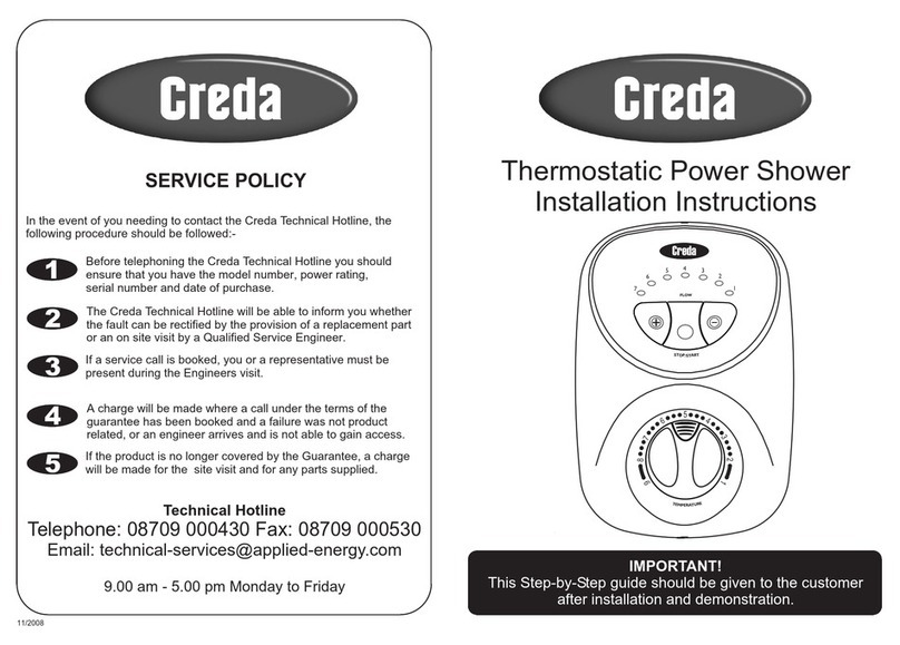
Creda Thermostatic Power Shower User manual

Creda

Creda Thermostatic Power Shower User manual

Creda EXPRESSIONS 500S User manual

Creda

Creda EXPRESSIONS 500S User manual

Creda Power Shower User manual

Creda

Creda Power Shower User manual

Creda AQUABLUE User manual

Creda

Creda AQUABLUE User manual

Creda PW E4ZC Manual

Creda

Creda PW E4ZC Manual

Creda 550C User manual

Creda

Creda 550C User manual

Creda Pumped User manual

Creda

Creda Pumped User manual

Creda AquaNoir User manual

Creda

Creda AquaNoir User manual

Creda JETSPA CONTEMPORARY User manual

Creda

Creda JETSPA CONTEMPORARY User manual

Creda Spa300c User manual

Creda

Creda Spa300c User manual

Creda Spa100 User manual

Creda

Creda Spa100 User manual

Creda 570 User manual

Creda

Creda 570 User manual

Creda FLORIDA PLUS User manual

Creda

Creda FLORIDA PLUS User manual

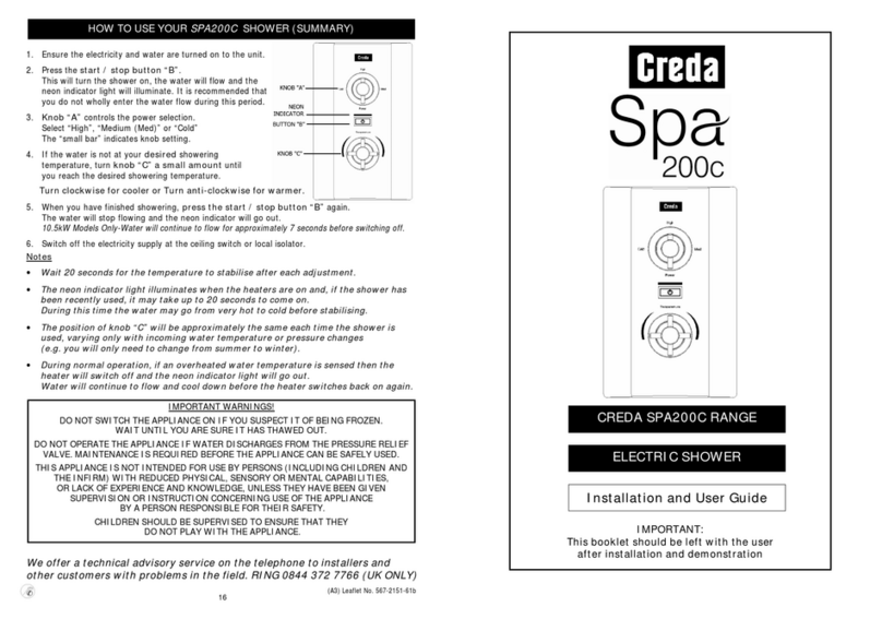
Creda SPA 200c User manual

Creda

Creda SPA 200c User manual

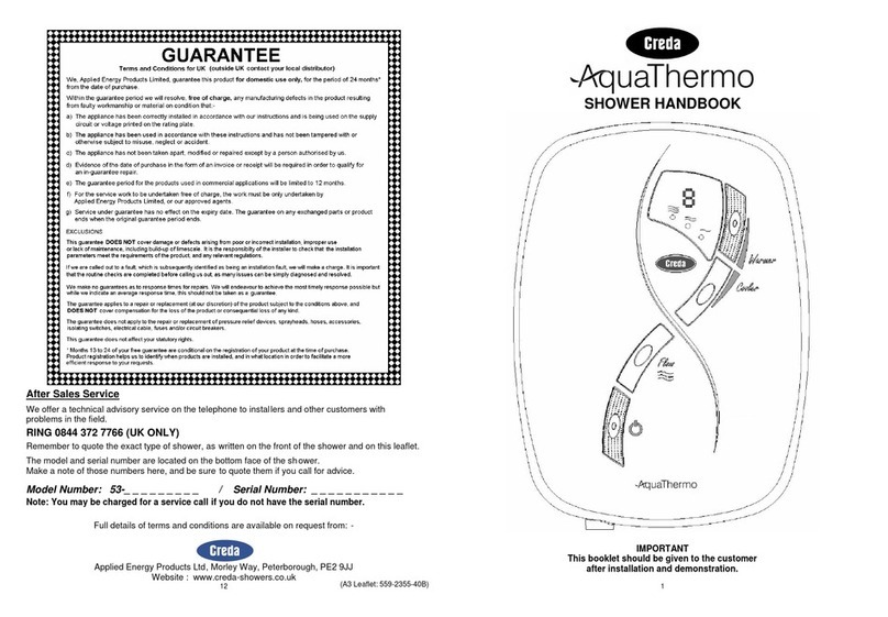
Creda Aquathermo 53 series User manual

Creda

Creda Aquathermo 53 series User manual

Creda Shower SPA User manual

Creda

Creda Shower SPA User manual

Creda BRISBANE 8.5 kW User manual

Creda

Creda BRISBANE 8.5 kW User manual

Creda Aquawave White User manual

Creda

Creda Aquawave White User manual

Popular Plumbing Product manuals by other brands

Toto NEOREST TBXM1A V300 installation guide

Toto

Toto NEOREST TBXM1A V300 installation guide

Halsey Taylor SCWT8A-CB-Q owner's manual

Halsey Taylor

Halsey Taylor SCWT8A-CB-Q owner's manual

Moen Show House TS883 Series owner's manual

Moen

Moen Show House TS883 Series owner's manual

Hans Grohe iBox Universal Plus Rough 01850181 Installation/User Instructions/Warranty

Hans Grohe

Hans Grohe iBox Universal Plus Rough 01850181 Installation/User Instructions/Warranty

Kebo F-5121-3 manual

Kebo

Kebo F-5121-3 manual

PEERLESS P99196LF manual

PEERLESS

PEERLESS P99196LF manual

saunalife Garden Series manual

saunalife

saunalife Garden Series manual

Kalia BF1220 CITE installation instructions

Kalia

Kalia BF1220 CITE installation instructions

Sapho KU211 user manual

Sapho

Sapho KU211 user manual

Armstrong 200 Series instructions

Armstrong

Armstrong 200 Series instructions

abi 14404 quick start guide

abi

abi 14404 quick start guide

Oras Medipro Installation and maintenance guide

Oras

Oras Medipro Installation and maintenance guide

KOLO Technic installation manual

KOLO

KOLO Technic installation manual

Bristan GLL RAPSNK4 C Installation instructions and user guide

Bristan

Bristan GLL RAPSNK4 C Installation instructions and user guide

Helvex Elegance 8124 installation guide

Helvex

Helvex Elegance 8124 installation guide

Kohler K1044435 Service Kit Instructions

Kohler

Kohler K1044435 Service Kit Instructions

BELLOSTA ELITE 9000 Installation instruction

BELLOSTA

BELLOSTA ELITE 9000 Installation instruction

Schon 65710N-B8401 Installation and care guide

Schon

Schon 65710N-B8401 Installation and care guide

manuals.online logo
manuals.online logoBrands
  • About & Mission
  • Contact us
  • Privacy Policy
  • Terms and Conditions

Copyright 2025 Manuals.Online. All Rights Reserved.