manuals.online logo
Brands
  1. Home
  2. •
  3. Brands
  4. •
  5. Creda
  6. •
  7. Plumbing Product
  8. •
  9. Creda Spa100 User manual

Creda Spa100 User manual

12
HOW TOUSE YOUR SPA100 SHOWER (SUMMARY)
IMPORTANT WARNINGS!
DO NOTSWITCHTHEAPPLIANCE ON IF YOU SUSPECT ITOF BEING FROZEN.
WAIT UNTIL YOU ARE SURE IT HAS THAWED OUT.
DO NOTOPERATE THE APPLIANCEIFWATER DISCHARGES FROM THEPRESSURE RELIEF
VALVE. MAINTENANCEIS REQUIRED BEFORE THE APPLIANCECAN BE SAFELY USED.
THIS APPLIANCEIS NOTINTENDEDFOR USE BY PERSONS (INCLUDING CHILDREN
AND
THE INFIRM)WITHREDUCED PHYSICAL, SENSORY OR MENTALCAPABILITIES,
ORLACKOF EXPERIENCE AND KNOWLEDGE, UNLESS THEY HAVE BEEN GIVEN SUPERVISION
ORINSTRUCTION CONCERNINGUSE OF THEAPPLIANCE
BY APERSON RESPONSIBLEFOR THEIR SAFETY.
CHILDREN SHOULD BESUPERVISED TO ENSURE THATTHEY
DO NOT PLAY WITH THE APPLIANCE.
1. Ensure theelectricity andwater are turned on to the unit.
2. Turn outer knob“A” clockwise to the “PowerSelect”
position of your choice.
= High Power
= Medium Power
= Cold Shower
The water will flow, andthe neon indicator light will glow.
It is recommended that you do notenter the water spray
during this period, even if the shower has justbeen used.
3. Turn inner knob “B” a small amount until you reach
the desired showering temperature.
Turn anti-clockwise(follow blue arrows) for cooler.
Turn clockwise (follow red arrows) for warmer.
4. When you have finished showering, turn outer knob “A” anti-clockwise to the “ ” position.
(Youhaveno need to adjust inner knob “B”).
5. Waterwillcontinue to flow for up to 3 seconds beforeswitching off.
This reduces the temperature of the water in the tank for the next user.
The neon indicator light will go out.
6. Switch offthe electricitysupply at the ceiling switch orlocal isolator.
Notes
•Wait 20 seconds for the temperature to stabiliseafter each adjustment.
•The neon indicates when the heaters are on and, if the shower has been recently used, it
may take up to 20 secondsto come on.
During this time the water may go from very hot to cold before stabilising.
Also, please note that the neon indicator doesnotlight when the shower isset to the
“ “ cold power setting.
•The position ofinner knob “B” will be approximately the same each time the shower is
used, varyingonly with incomingwater temperature or pressure changes
(e.g. you will only need to change from summer to winter).
•During normal operation, if an overheated water temperature is sensed then the heater
will switch off and the neon indicator will go out.
Water will continue to flow and cool down before the heater switches back on again.
We offer a technical advisory service on thetelephone: RING 0844 372 7766 (UKONLY)
(A4) LeafletNo. 555-2136-61b
IMPORTANT:
This booklet should be leftwith the user after
installation and demonstration
CREDA SPA100
SMART TECHNOLOGY
ELECTRIC SHOWER
Installation and User Guide
2
INTRODUCTION
If you experience any difficulty with theinstallation or operation of your new
shower, then please refer to the “What to do if things go wrong” section in this
manual beforecontacting us.
Thank you for purchasing a quality Creda SPA100 Electric Shower manufacturedin England.
To enjoy yournew showerat its best, pleasetake timeto readthis manualthoroughly to
familiariseyourself with all instructions,BEFORE beginning installation.
The Creda SPA100 is an electric shower incorporating our “Smart Technology” and a unique dual
control combining on/off, power select and flow/temperature control.
Your shower is designed to stabilise temperature
changes caused by water pressure fluctuations.
These can resultfrom toilets being flushed ortaps being turned on and off.
When this happens your showering temperature will be held within a controlled band,provided that
the minimum pressure required by the shower is maintained (see “Effect of Other Water Devices”).
1. Your shower has beendesigned for convenience, economy and safety of use, provided that it is
installed, used and maintained in good working order and in accordance withour instructions and
recommendations.
2. Allwiring and installation must besupervised by a suitably qualified person.
3. THISAPPLIANCE MUST BE EARTHED.
4. The installation must be in accordance with the current edition of BS.7671 (the“IEE Wiring
Regulations”) and “Part P” of the “Building Regulations” in force at the timeof installation.
Installations outside England and Wales must also conform to any local regulations in effect.
This appliance is intended to be permanently connected to thefixedelectrical wiringof the mains
supply with its own dedicatedsupply.
5. This appliancemust NOT be fitted where it maybesubjected to freezing conditions
6. DO NOT switch the appliance on if you suspect itof being frozen.
Wait until you are sure it has thawedout.
7. DO NOT fit any sort of tap or control on the applianceoutlet. The appliance is designed to have
an open outlet and should only be used with “Creda” recommended fittings.
8. Take careto avoid restrictingthe outlet of the pressure relief device. If water is discharged from
thepressure relief device,maintenance will be required before the appliance can be safely used.
9. Isolate themains electrical and water supplybefore removing thefront coverof theappliance.
Section
Introduction
.. . . .. .. . ... .. .. .. .. .. ... .. .. .. .. ..... .. . . . .. ...... ..
Important Safety Information . . . .. ...... .. . .. .. ...... .. .. . .. ...... . .. .
How to install your SPA100 Shower . . . .. ......... .. . .. ....... .. .. .. .....
How to maintain your SPA100 Shower .. . . .. .. .. ..... .. .. .. . . ..... .. .. .. .
How to use your SPA100 Shower (Detailed) . . .
. .. .. .. ... .. .. . . . ...... .. .. .
What to do ifthings go wrong (1) Self Help . .. .. .. .. ..... .. .. . . ....... .. ..
Additional Accessories and Common SpareParts ..... . .. .. .. ... .. .. .. .. .. ..
What to do ifthings go wrong (2) Professional Service . . . ... ... ... . .. .. .. ....
Creda AfterSales Service . . . ... ... .. .. .. . ... ... .. . .. .. ... .. .. .. .. .. ..
How yourSPA100 ShowerWorks . . . . . . ...... .. .. .. . ...... .. . .. .. ...... .
Guarantee and ContactDetails . ........ . .. .. ....... .. .. .. . .... .. .. .. ..
How to use your SPA100 Shower (Summary) ... .. .. .. . .... .. .. . .. .. ... ... .
Page
2
2
3
6
7
8
8
9
9
10
11
12
CONTENTS
IMPORTANT SAFETYINFORMATION
11
:
Full details of terms and conditionsare available on requestfrom:-
APPLIED ENERGY PRODUCTS LIMITED
MORLEY WAY, PETERBOROUGH PE2 9JJ
TEL: +44 (0) 844 372 7761
FAX: +44 (0) 844372 7762
Website: www.applied-energy.com
GUARANTEE AND CONTACTDETAILS
10
1. Water is heated instantaneouslyas it flows over the
heating elements in the copper cylinder(Diagram 8).
2. The heaters are only switched on when sufficient
water is flowing.
This is done automaticallywith a switch which
works on water pressure and is indicated by the
neon light illuminating depending on the power
selectedby outerknob“A”.
3. The wateris turned on and off by thesolenoid
valve built into the shower.
This is switched on when outer knob “A” is
clicked clockwise.
4. The flow of water isautomatically held at the level set
bythe user even though the supplypressure may vary
(see “Effectof Other Water Deviceson Incoming Water Supply”).
5. Ifthe water supply falls below a set limit, the pressure
switch will operate and switch off the power to the elements.
This is indicated by the neon lightgoing out (see “Effect of Other Water Devices on Incoming
Water Supply”).
6. As afurther safeguard,a thermal cut-out switches thepower off if the water temperature
climbs above the set limit. This cut-out,which gives an audible click, mayalso operate due to
residual heat when the showeris switched off.
It will reset itself ifwater is run through the shower for 10 to 20 seconds.
7. The pressurerelief device is to safeguard against abnormal pressure conditions, and provides a
level of appliance protection should an excessivebuild ofpressure occurwithin the shower.
Effect of Seasonal Incoming Water Temperature Changes
The required water temperature is achieved by adjusting the rate of water flow.
Diagram 9 shows the principle involved in relating temperature rise to flow rate.
The higher the water rate the lower the temperature and vice versa.
The temperature of the watersupplied from the mains can vary considerably
throughout the year from 5 to 20°C.
This means that in the winter, flow rate will be less than in the summer to
achieve the same outlettemperature.
In summer the “ (medium)” power setting may give adequate hotwater.
Effect of OtherWaterDevices on IncomingWaterSupply
Your shower is designed to stabilisetemperature changes caused by waterpressure
fluctuations. These can result from toilets being flushed or taps being turned on and off.
When this happens your showering temperature will be held within a controlled band,provided that
the minimum pressure required by the shower is maintained.
Your shower requires a minimum running
pressure of 69kPa (0.7 bar, 10 psi).
At pressures above 69kPa (0.7 bar,10 psi) itwill minimise temperature fluctuations as detailed
above. If thewater pressure falls below 69kPa(0.7 bar, 10 psi) itis likely that the pressure switch
will turnoff the powerto the heating elements,resulting inacold shower.
This will be indicated by the neon light going out.
HOWYOUR SPA100 SHOWER WORKS
3
WARNING: ALL WIRING AND INSTALLATION MUST BE SUPERVISEDBY A SUITABLY
QUALIFIED PERSON.
WARNING: DONOT INSTALL THIS SHOWER WHERE IT MAY BE SUBJECTED TO
FREEZING CONDITIONS
We recommend that the installation is done in the following sequence.
a. Fixing the showerto the wall b. Plumbing c. Electrical connections
a. FIXING THE SHOWER TO THE WALL
1. Position the riser rail at a convenientheightfor majority of users
as detailed in Diagram 1a and mark itsposition.
2. Position the heater so that the top of the unit is horizontal and level
with, or a maximumof 0.6metres (2ft) belowthe top of the
riser rail. Chooseaflat piece of wall to avoid the possibility of
distorting the backplate thus making the frontcover a poor fit.
3. Adjust the position to get the most convenient arrangement taking
the following into account.
•The heater must not be mounted in the handset direct spray.
•The handset mustnot be able to come into contact with used water
in the cubicle, bath or basin. If it can, evenafter the hose has been
retainedbythe retaining ring (see Diagram 1b), then a vacuum
breaker mustbe fitted (available from us).
4. Fix the riser rail with screws provided.
The fixing holes at thebase of the bracketswill be disclosed by
removing the plastic fronts.Assemble as shown in Diagram 1b.
5. Decide the position of the electrical cable into the unit. If top orbottom entryis chosen
(according to Diagram 7 on page 9), cut away the walls in thebackplate as shown in Diagram 2.
6. Decide the position of entry of the cold waterpipe into the unit.
Iftop, cutawaythe backplate.
If rear, please read the section on plumbing.
Ifbottom, remove the front cover (completewith knobs) andcut away the detachable corner
section as shown.
HOWTO INSTALLYOUR SPA100 SHOWER
4
7. Ifyou have not yet done so, remove thefront cover assembly byundoing the retaining screws at
the top and bottom of the unit and lifting the cover off.
Your shower is provided with 2 fixing positions in the backplate (see Diagram 7 on page9).
The top-fixing holeis a “key-hole”slot (another key-hole is providedfor alternate fixing), and
should be marked and drilled first.
Tighten top screw with head protruding about 10mm fromthe wall and hook the backplateover
the screw head. This allows for correct and accurate alignmentof your shower before marking
and fixing thebottom position.
You maynot wish to tighten up both screws at this stage as the holesare elongated to allow for
adjustment after otherconnections have taken place.
b. PLUMBING
WARNING: ENSURE THAT THE MAINS WATER SUPPLY MEETS THE REQUIREMENTS
BELOW BEFORE CONTINUING WITHINSTALLATION.
The heatermust be connected to the mains cold watersupply.
This must have a minimumrunning pressure of 69kPa (0.7 bar, 10 psi)
and a maximum pressure of 690kPa (7.0 bar, 100 psi).
WARNING: BEFORE CONNECTING THE PIPE WORK TOTHE SHOWER,
ENSURE THAT THE PIPE WORKIS FULLY FLUSHED OUT.
1. Unscrewthe “Red Cap” from the shower outletpipe and discard it in a suitable manner.
This has been used to seal the showerduring transit,and is no longer required.
2. Itis recommended that a WRAS (Water Regulations Advisory Scheme) listed isolating valve is
fitted to the incoming mains cold water before the shower unit.
This will allow the unit to be serviced or exchanged without having to turn off thewater atthe
water stop valve.
3. The heater can be fed from a header tank provided this has a minimum head of 7 metres (23ft).
4.
Ø15mm copper orstainless steel pipe shouldbe used.
To avoid cross threading, DO NOT REMOVE the nut
from the elbow whenpositioning the pipe.
Iftop entry is required,turn the elbow 180° into the required position.
Ifrear entry is required, treat as top entry with an additional “Yorkshire” elbow (soldered type)
for fitting into the rearchannel.
In multiple installations, correct pipe work sizes should be calculated to maintain adequate flow
to each shower.
5. Itis permissible to use a WRAS (Water Regulations Advisory Scheme) approved sealant sparingly
whilst avoiding excess finding its wayinto the shower operating parts.
6. With isolating valve connected, flush the pipework through to remove any particles etc,
before making the final connection to the shower.
Blockage in thewaterways (particularly the handset and solenoid valve) will prevent the heater
working properly. Note: You may be charged for aservice call if itis due toincorrect installation.
7. The shower is designed to havean open outlet and should only be used with “Creda”
recommended fittings.
Do not connectthe handsetuntil after the shower front cover and corner section are fitted.
WARNING: DONOT FIT A TAP ON THE SHOWER OUTLET.
WARNING: TAKE CARE TO AVOID RESTRICTING THE OUTLET OF THE
PRESSURE RELIEFDEVICE 9
WHAT TODOIFTHINGSGOWRONG (2)
CREDA AFTER SALES SERVICE
PROFESSIONAL SERVICE
If the previous “Self Help” checks fail to restorethe performance, you should seek professional help.
The personwho installed the shower is probablythe best oneto investigate and correct itand is
certainly the person to contact if you have had a problem in the guaranteeperiod.
The following additional checklist is providedforthe benefit of the qualified service person.
WARNING: SWITCH OFF THE ELECTRICITY AT THE LOCAL ISOLATOR
BEFORE REMOVING THE COVERTO MAKE CHECKS
Watertoo HOT Water flow restricted by blockage in filter of solenoid valve.
Switch off water, loosen inlet connection to solenoid,removefilter in solenoid
with long nosed pliers and flush clean.
Watertoo COLD Check circuit through thermal cut-out.
Check circuit through microswitches onthe pressure switch.
Check each element circuit.
Check tightness of electrical connections.
No control over
waterflow Check Drive Gite is correctly engaged into Control Knob (see Diagram 5)
Undo headworks of stabiliser valve.
Check stabiliser is in place and remove any debris in valve.
Water discharges
from pressure
relief valve
Check for cause of high pressure and remove it.
Blockage on outlet e.g. blockedshower handset.
Replace the pressure relief disc (not covered by guarantee).
Water does not
flow when outer
knob “A” is turned
Check circuit through solenoid coil. If defective then replace.
Check circuit through microswitches. If defective then replace.
Power supply not reaching shower.
We offera technical advisory service on the telephone to
installers and other customers with problemsin the field.
RING 0844372 7766 (UKONLY)
RING YOURLOCAL DEALER(Export Variants)
Some spare parts (see later section) can be supplied
against Credit or Debitcards.
RING 0844372 7750 (UKONLY)
Remember to quotethe exact type of shower,aswritten
on the front of the showerand on this leaflet.
The model and serial number arelocated on the bottom
face of the shower.
Make a note of those numbers here,and be sure to quote
themif you call for advice.
Model Number: 53-67_ _ _ _ _ __ _ _ __ _ _ _
SerialNumber: _ _ _ _ _ _ _ __ _ _ _ _ __ _ _
Note: You may be charged for a servicecall
if you do not have theserial number.
8
SELF HELP
If the shower is notworking satisfactorily, make thefollowing checks before calling out the installer
.
Any one of these adjustments could restorethe performance.
The shower cycles
from HOTto COLD Theshower temperature is set too hotcausing thethermal cut-out (safety
device) to operate.
Turn innerknob “B” anti-clockwise in the direction of the “blue arrows” to
increase water flow.
Slowly increase thewater temperature by turninginner knob “B” clockwise in
the direction of the “red arrows” until a comfortable showeringtemperature has
been reached.
YouMUSTWAITapproximately20 seconds for each adjustment toaffect the
water temperature.
“ (medium)” setting may need tobe selected.
Water too HOT Increase water flow by adjustinginnerknob “B” anti-clockwise (directionof the
“blue arrows”).
“(medium)” setting may need tobe selected.
Increase pressure to water supply e.g. fully openservice valve orstop cock.
Check hose is not kinked restricting the water flow.
Cleanshower handset.
Water too COLD Check poweris on by neon being illuminated.
Decrease waterflow by adjustinginner knob “B” clockwise (direction of the “red
arrows”).
“ (high)” setting may needto be selected.
Spraypattern poor Cleanthe shower handset.
Water takes longer
to heat up Thermalcut-out has operated after previous use
(automatically resets when unit cools down)
“(high)” setting may needto be selected.
Water goes cold
while using
shower
Check neon light is on.
Check water pressure has notfallen so faras toletpressure switch cut out,
e.g. Another tap drawing water off.
Raise position of shower handset.
Water continues to
flow when
“ (stop)” selected
This is normal.
Theshower includes ashutdownfeaturethat means thewaterwill continueto
flow for up to 3 seconds after “ (stop)” has been selected.
Brokenparts Please contact our spares department on 0844 372 7750 (UK only).
Fitting instructions areprovidedwithmost spares
Please Note:- The fitting of Spare Parts mustbe supervised by a suitably qualified person.
White 2 metre Shower Hose CatNo. 83792578 Front Cover (Creda) CatNo. 93550810
White 1.25 metre Shower Hose CatNo. 93593538 TankBase Assy(7.2kW) CatNo. 93597858
Chrome Multi-Mode Accessories CatNo. 83595318 TankBase Assy(8.5/9.5kW) CatNo. 93597859
Chrome Premium Accessories CatNo. 83595319 Solenoid Valve CatNo. 93597868
Chrome Curved Accessories Cat No. 83595320 NeonCable Assy CatNo. 93593576
Curtain and Rail Pack CatNo. 83792812 Tank Clip CatNo. 93768309
Curtain and Rail Pack with PRV Washer CatNo. 93795817
Non-SlipMat CatNo. 83792811 Cylinder“O”-Ring CatNo. 93795809
WRAS Water Isolating Valve CatNo. 93792452 Thermal Cut-Out 50/88°C CatNo. 93597871
Handset CatNo. 93590736
WHAT TODOIFTHINGSGOWRONG (1)
ADDITIONAL ACCESSORIESCOMMON SPARE PARTS
Additional accessories and spareparts can be
supplied against anyCredit orDebit cards
from Creda Sales Hotline 0844 372 7750 5
c) ELECTRICAL
WARNING: THIS SHOWER MUST BE EARTHED.
The electrical installation must be in accordance with the currentBS.7671 (IEEWiringRegulations)
and “PartP” of the BuildingRegulations and/orlocal regulations
1. The shower unit is designed for a single phase AC electrical supply.
Pleasecheck therating plate on the unit to see what details apply to your shower.
AS A GUIDE ONLY (* Only applies if external earth impedance is less than 0.35 Ohms)
Rating CableSizes
Fuse / MCB
Cable Length
4.0mm²
6.0mm² 32AType B MCB 21m Max.
35m Max.
7.2 / 6.6kW 240 / 230V
.6.0mm²
10.0mm² 40AType B MCB 27m Max.
45m Max.
6.0mm²
10.0mm² 40AType B MCB 27m Max.
45m Max.
8.5 / 7.8kW 240 / 230V 6.0mm²
10.0mm² 45ABS.1361 fuse 12m Max.*
21m Max.*
6.0mm²
10.0mm² 40AType B MCB 27m Max.
45m Max.
9.5 / 8.7kW 240 / 230V 6.0mm²
10.0mm² 45ABS.1361 fuse 12m Max.*
21m Max.*
Remember to upgrade the cableif it runs in thermal insulation in a loft, or foralonger distance.
2. A means for disconnection inall poles must be incorporated in the fixed wiring in accordance
with thewiring rules.
Werecommend a ceilingswitch mounted in a convenient position.
3. Cut back cable as in Diagram 3. Connect cable to terminal block making sure thatall the
retaining screws are VERY TIGHT and thatno cableinsulation is trapped under the screws.
WARNING: FAILURE TO COMPLY WITHTHESE INSTRUCTIONS COULD RESULT IN
FAILURE OF THE TERMINAL BLOCK
4. Re-Fitthecorner section back into the backplate.
6
HOWTO MAINTAIN YOUR SPA100 SHOWER
5. Re-Fitthefrontcover (see Diagram 5) and replace the top and bottom fasteningscrews.
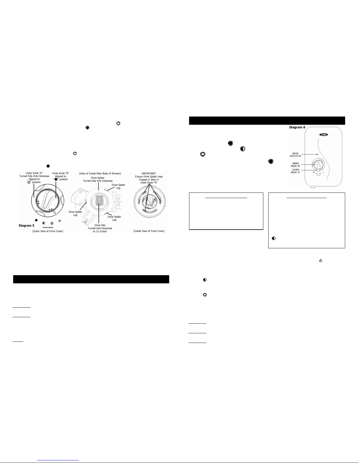
a. Ensure outer knob “A” is aligned fully anti-clockwise to the “ (stop)“position.
b. Ensure innerknob “B” is aligned to the “ (high)” position.
c. In the main body ofthe shower,turn the “Drive Spider” fully anti-clockwise until it stops.
d. In the main body ofthe shower,turn the “Drive Gite” anti-clockwise until it is at “12 o’clock”.
e. Fitthe front cover of the shower to the mainbody ensuring that the 3 x “Drive Spider Legs”
engage with theslotsin outer knob “A”.
f. Check that outer knob “A” has been correctly aligned by ensuring that all 3 power settings can
be selected, and returns to the “ (stop)“position.
g. Check that innerknob “B” has been correctlyalignedby turning clockwise and ensuring that
knob turns approximately 3/4 of a turn (270°) and when turned back fully anti-clockwise,
returns to the “ (high)” position.
6. Fit the shower hose, and operate the shower firstwithoutthe handsetto flushout particles,
fit thehandset and then operate the shower as on page 7 or 12 and check:
a. That the water getsto a satisfactorytemperature.
b. Waterflow can be adjustedbyinner control knob“B”.
c. Power selection operates in all 3 positions,giving a change in watertemperature and
that theneon lightfunctions correctly.
d. Check again for leaks and that the holes in the shower handsetare not blocked
8. DEMONSTRATE OPERATION TOUSERS
It isrecommended thatthe shower unit and hose etc.becleaned using a soft cloth and that theuse
ofabrasiveor solvent based cleaning fluid be avoided, especially on any plated finishes.
We recommend that before any cleaning,the isolating switch be turned off, thus avoiding
accidentallyswitchingon the shower.
WARNING:
YOU MUST REGULARLY INSPECTTHESHOWER HOSE FOR WEAR ANDDAMAGE.
REPLACEIF NECESSARY, OR EVERY TWO YEARS, WITH A CREDA APPROVED PART.
WARNING: IN ORDER TO MAINTAINTHE PERFORMANCEOFYOURSHOWER,
YOU MUST CLEANTHESHOWER HANDSETREGULARLY.
All water contains particles of lime, which build up in theshower handset and unit reducing the
performance. It is therefore important to clean the shower handset by simply rubbingthe rubber
nozzles, or soaking in aproprietary lime-scaleremover and rinsingthoroughly before use.
NOTE: After use itis normal for some water to drip fromthe shower handset for a few moments.
Thisinhibits scale build-upover prolongeduse.
7
IF WATERIS TOO COLD
Turn innerknob“B” clockwise in the
direction of the “red arrows” to “1 o’clock”
and continue turning clockwise until you get
the water temperature of your liking.
Wait 20 seconds after each adjustment
forthe water temperature to stablise.
IF WATER IS TOO HOT
Turn inner knob “B” anti-clockwise in the
direction of the “blue arrows” to “11 o’clock”
and continue turning anti-clockwise until you
getthe water temperature of your liking.
Wait 20seconds after each adjustment for
the water temperature to stabilise.
Ifafter turning fully anti-clockwise,water is
still too hot,adjust outer knob “A” to
“(medium)” setting and re-adjust as above.
Water flow will be reduced on this setting.
1. Ensurethe electricity and water are turned onto the unit.
2. Yourshower has 3 power settings selected by turning outer
knob “A” (see Diagram 6).
The most popular is“ (high)”.
There are also options for a “ (medium)”
or “ (cold)” shower (seenotes 8 and 9).
For this exampleturn outerknob “A” to “ (high) ”
andset inner knob “B” to “12 o’clock”.
3. The water will flow and the neon light will glow brightly.
4. Allow about 20 seconds forthe temperature of the water
to stabilise. Itis recommendedthat you do notwholly enter
the water spray during this period,even if the showerhas just been used.
5. Once a temperature setting to your liking
has been achieved,innerknob “B” will rarely
need adjusting.You musthowever take into
account required adjustments for variations
of incoming mains water temperature between summer and winter (see “Effect ofSeasonal
Incoming Water Temperature Changes” page 10).
6. When you have finished showering, turn outer knob “A” anti-clockwiseto the “ (stop)”
position. Water willcontinue to flowfor upto 3 seconds before switchingoff.
This reduces the temperature of the water in thetank for the next user.
Switch off the electricity at the ceiling switch or local isolator.
7. The “ (medium)” setting of outer knob “A” reduces the power used by the shower givinga
cooler shower or the option of reduced waterflow. This option is mainly used forsummer usage
and if this is used then innerknob “B” must be re-adjusted.
8. The “ (cold)” setting of outer knob “A”will supply water without any heating,and the neon
light will go out.
9. Yourshower is designed to stabilisetemperature changes caused bywater pressure
fluctuations (see “Effectof Other WaterDevices on Incoming Water Supply” page 10).
10. Note thatinner knob “B” IS NOT A TAP anddoes not turn thewateroff.
WARNING: DO NOT SWITCH THE SHOWER ON IFYOU SUSPECT ITOF BEINGFROZEN.
WAITUNTIL YOU ARESURE ITHAS THAWED OUT.
WARNING: DO NOT OPERATE THE SHOWER IFWATER IS DISCHARGED FROM THEPRESSURE
RELIEF VALVE. MAINTENANCE ISREQUIRED BEFORE THE SHOWER CAN BE USED.
WARNING: CONSIDERATION SHOULDBE GIVEN TOSUPERVISING THEYOUNG, ELDERLY AND
THE INFIRM WHILST THEY USE THIS SHOWER.
HOWTO USE YOUR SPA100 SHOWER (DETAILED)

Other Creda Plumbing Product manuals

Creda AQUABLUE User manual

Creda

Creda AQUABLUE User manual

Creda Florida Spa User manual

Creda

Creda Florida Spa User manual

Creda 550C User manual

Creda

Creda 550C User manual

Creda Shower SPA User manual

Creda

Creda Shower SPA User manual

Creda Spa300c User manual

Creda

Creda Spa300c User manual

Creda BRISBANE 8.5 kW User manual

Creda

Creda BRISBANE 8.5 kW User manual

Creda Aquawave White User manual

Creda

Creda Aquawave White User manual

Creda FLORIDA PLUS User manual

Creda

Creda FLORIDA PLUS User manual

Creda AquaNoir User manual

Creda

Creda AquaNoir User manual

Creda PW E4ZC Manual

Creda

Creda PW E4ZC Manual

Creda 570 User manual

Creda

Creda 570 User manual

Creda Aquathermo 53 series User manual

Creda

Creda Aquathermo 53 series User manual

Creda SPA 200c User manual

Creda

Creda SPA 200c User manual

Creda EXPRESSIONS 500S User manual

Creda

Creda EXPRESSIONS 500S User manual

Creda Pumped User manual

Creda

Creda Pumped User manual

Creda JETSPA CONTEMPORARY User manual

Creda

Creda JETSPA CONTEMPORARY User manual

Creda Thermostatic Power Shower User manual

Creda

Creda Thermostatic Power Shower User manual

Creda Power Shower User manual

Creda

Creda Power Shower User manual

Popular Plumbing Product manuals by other brands

Helvex Nuva TV-200 installation guide

Helvex

Helvex Nuva TV-200 installation guide

Hans Grohe AXOR Urquiola 11425000 Instructions for use/assembly instructions

Hans Grohe

Hans Grohe AXOR Urquiola 11425000 Instructions for use/assembly instructions

Laufen LIS CW1 H894660 manual

Laufen

Laufen LIS CW1 H894660 manual

DURAVIT DuraSystem WD1011 000 000 Mounting instructions

DURAVIT

DURAVIT DuraSystem WD1011 000 000 Mounting instructions

Signature Hardware 902828 quick start guide

Signature Hardware

Signature Hardware 902828 quick start guide

baliv DU-2061 instruction manual

baliv

baliv DU-2061 instruction manual

AM.PM GEM S W93G-403-090BT Assembly instructions

AM.PM

AM.PM GEM S W93G-403-090BT Assembly instructions

SFA SANIPACK P30 Installation and maintenance instructions

SFA

SFA SANIPACK P30 Installation and maintenance instructions

miseno MNO621A quick start guide

miseno

miseno MNO621A quick start guide

Blaufoss 36824 installation guide

Blaufoss

Blaufoss 36824 installation guide

BATHSELECT BST-959-ORB installation instructions

BATHSELECT

BATHSELECT BST-959-ORB installation instructions

Uponor KaMo Combi Port PRO XU Installation and operation manual

Uponor

Uponor KaMo Combi Port PRO XU Installation and operation manual

Elkay DLRQ222212 Specifications

Elkay

Elkay DLRQ222212 Specifications

Kalia BELLINO 101464 Installation instructions / warranty

Kalia

Kalia BELLINO 101464 Installation instructions / warranty

Quatreau Touch 553-B instruction manual

Quatreau

Quatreau Touch 553-B instruction manual

BELLOSTA edward 0808/CC Installation instruction

BELLOSTA

BELLOSTA edward 0808/CC Installation instruction

Vola 5400NV FITTING INSTRUCTION

Vola

Vola 5400NV FITTING INSTRUCTION

Pfister Masey 8P8-WS2-MCS Quick installation guide

Pfister

Pfister Masey 8P8-WS2-MCS Quick installation guide

manuals.online logo
manuals.online logoBrands
  • About & Mission
  • Contact us
  • Privacy Policy
  • Terms and Conditions

Copyright 2025 Manuals.Online. All Rights Reserved.