manuals.online logo
Brands
  1. Home
  2. •
  3. Brands
  4. •
  5. Creda
  6. •
  7. Plumbing Product
  8. •
  9. Creda Aquathermo 53 series User manual

Creda Aquathermo 53 series User manual

12
AfterSalesService
Weoffera technical advisory service onthe telephone to installers and othercustomers with
problems in the field.
RING 0844 3727766 (UK ONLY)
Rememberto quote theexacttypeof shower, as written on the front of the shower and on this leaflet.
The model and serial number arelocated on thebottomface of the shower.
Make anote of thosenumbershere,and be sure to quote them if you call foradvice.
Model Number:53-_ __ ___ _ __ / Serial Number: __ _ ___ __ _ _ _
Note:You may be charged for a service call if you do not have the serial number.
Full detailsof terms andconditionsareavailable on requestfrom: -
Applied EnergyProductsLtd, MorleyWay,Peterborough, PE2 9JJ
Website : www.creda-showers.co.uk (A3 Leaflet: 559-2355-40B)
1
SHOWER HANDBOOK
IMPORTANT
This bookletshould begiven to the customer
after installation anddemonstration.
2
Thank you forchoosing a quality“Creda” product manufactured in Peterborough,England.
Contents
User information Page
How to use your shower 2
Routine Maintenance 4
How your shower works 5
Troubleshooting 6
Available spares 10
InstallerInformationPage
Fixingthe shower tothe wall 8
Plumbing 9
Electrical 9
Commissioning 10
Guarantee 12
Warning
Do Not Switch The Shower On IfYouSuspect It Of Being Frozen,
Wait UntilYou Are SureThat It Has BeenCompletelyThawed Out.
How ToUse Your Shower
SwitchOn Electricity at ceiling / isolating switch.
Press Start /StopButton in the centre.
(Confirmed with a single bleep)
The unit will start and themotorised valve willreset.
Displaywill usuallylight up number 1.
The digit willincrease until displayshowsnumber6.
The average showering temperature.
When the unit hasgot closeto thissetting it sounds a
doublebleep andthe unit is ready for use.
The unit will only count up & double bleep once per
showersession.
Flow light willbe on high.
To IncreaseTemperature - Press the warmer
button once in the centre (Confirmed witha single bleep).
The number will change tothe newsetting.
i.e. Display will change from digit 6to digit 7
Wait for afewseconds forthe shower to increasethe
temperature to the new setting.
Repeat this for your ideal setting waiting each time for the
temperature to be achieved.(Maximumsetting isdigit 9).
To DecreaseTemperature - Press the cooler
button once in the centre (Confirmed witha single bleep)
The number will change tothe newsetting.
i.e. Display will change from digit 6to digit 5
Wait for afewseconds forthe shower to decrease the
temperature to the new setting.
Repeat this for your ideal setting,waiting eachtime for
the temperature to be achieved
11
This page hasbeen left blank forthe addition of any notesyou maywishto make:-
10
d) Commissioning
Ensurethe water and electricity are switched on to the unit.
Pressthe START/STOP button then change thetemperature settingto number1 bypressing the
COOLERbutton 5 times.
If the button does notrespond,ensure that the flyinglead from the PCB has been connected tothe
front cover (fig 12).
Allowthe unit tofill and waitfor the waterto come out of the handset.
Change setting uptonumber6 bypressing the warmer button, check that the outlet temperature
increases to comfortable temperature and that, when pressing theflow button the flowdoeschange.
Check forleaks.
PressSTART/STOP button to switch the unit off.
Thiscompletes the commissioning.
Demonstrate OperationTo User.
Please leavethese instructions with user forfuturereference.
Spare Parts(RING 0844 3727750)
Spare parts Cat No.
Solenoid valve + seals93-594101
Triac PCB 93-594102
Flow transducer 93-594117
Flow assembly+ motor (no outlet) 93-594104
Valve motor 93-594105
Cutoutassembly+ cables 93-590326
Hose outlet assemblycomplete 93-594110
Cable entries (top / bottom)Grey 93-594129
Side section (Grey) 93-594130
Logic PCB 93-594118
Frontcoverassemblycomplete 93-590359
P.R.V. housing complete 93-594115
Cable pack(all internal cables) 93-594116
1.25m Chrome ShowerHose 93-797641
Please Note:- The fitting of all sparesshould be supervisedby a suitably qualified person.
3
To Change Flow Rate
Pressthe flowbutton in thecentre
(Confirmed with a single bleep)
Thisreducesthe flow without changing thetemperature setting.
(Note: Asthe flowchanges, the water temperaturemaygo up and
down slightly)
Pressonce and the flow will reduce to medium.
Press it again and it will reduceto low.
On switchingon the shower,the flowalwayscomes on in the high
flow condition.
Switching Off
When you have finished showering pressthestart /stop
button in the centre. See fig.1 (Confirmed with 3 shortbleeps)
The waterwillcontinue to run for a few seconds so thatthe unit is
cooled down readyforthe next time the shower is used.
While this ishappening the display willcircle round and round
(see fig.5).
The unit will thenswitch off automatically.
SwitchOffElectricity at ceiling/ isolating switch.
OverTemperatureShutdown
If an abnormal condition occurswhich causesthe water to get too
hot,
the unit will automatically shutdownstraight away and the
water willstop flowing.
Thisisto preventanyhotwatercoming out of the handset.
Thisisindicated by 8shortbleeps and the displayflashing a
lowercase “o” and then “t” (see fig.6).This willcontinue untilthe
water is at a safe temperature. The unit will thenswitchoff
automaticallyand will need to be restarted inthe normal way.
Itcan take along time for theunittoreach asafe temperature.
To speed this temperaturereduction up, the hot water can be
purged from the unit.
Fig.5
4
Purging
While the unit is in Over Temperature shutdown mode
press the cooler andflow button together for 20
seconds.(See fig.7)
Thiswill switch the wateron only whilethebuttonsare
pressed.
Caution!!
WaterWill Be Hot stand clear of the sprayfrom the
handset.
The unit will then switch off automatically with 3 short
bleeps when a safe watertemperature has been reached.
In Order To Maintain The Performance OfYour Shower
You Must Clean The ShowerHead Regularly.
All watercontains particles of lime-scale,which build up in the showerhead and unit reducing the
performance.
Itistherefore important toclean the showerhead by simply rubbing the
rubber nozzles or soaking in proprietary lime-scale remover and rinsing
thoroughlybefore use.
The frequencyof thiswillvaryfrom weeklyto quarterlydepending on the
water hardnessand experience.
In somewinter conditions, when theincoming mainswater isparticularly cold
it maybenecessarytoselect the innerorouter spray pattern only; this will
ensure correctoperation of the showerwitha slightlylowerwater flow rate.
Afteruse it isnormal for some water todrip from thesprayhead fora few
moments. Thishelpsprevent scale build up over prolonged use.
Routine Maintenance
Itisrecommend that as well as checking the showerhead asdetailed above, the shower unit,riser
rail,hose etc. be cleanedusing a soft cloth and that the use of abrasiveorsolvent based cleaning
fluid be avoided, especiallyon any plated finishes.
Werecommend thatbeforeany cleaning, the isolating switch be turnedoff, thus avoidingaccidentally
switching on the shower.
You Must Regularly Inspect The Shower Hose For Wear And Damage.
Replace If Necessary,Or Every Two Years, WithOur Approved Part.
Thisappliance isnot intendedfor usebypersons(including children and the infirm)
withreducedphysical, sensoryormental capabilities, or lackof experienceand
knowledge, unlesstheyhavebeengivensupervision orinstruction concerning
useof theappliance byapersonresponsiblefortheir safety.
Childrenshouldbesupervisedtoensurethattheydonot playwiththeappliance.
9
b) Plumbing
Werecommend thataWRAS (WaterRegulations AdvisoryScheme) listed isolatingvalve befitted
between the risingmain and the unit.
Thiswill allowthe unit to be serviced withouthaving to turnoff the housewater at thestop valve.
The unit should be connected to themains cold watersupply. This musthave a minimum running
pressureof 0.07 MPa (0.7bar /10 p.s.i.)and a maximum pressure of 1MPa(10bar /145 p.s.i.)
The unit can befed from a header tank provided this has aminimum headof 7 metres(23ft).
Standard Ø15mm copper or stainlesspipe should be used. Connection to the unit isviaa Ø15mm
plainshankon thesolenoid valve.Acompressionelbow orpushfit connector can be used.
(Stainlesspipe isnot recommendedfor push fit).
Using anIsolating valve, flushthe pipe work through to
removeparticles etc., before making the final connection to
the shower.A blockage in the waterways(particularlythe spray
plate and solenoidvalve)will prevent the unit from working
correctly.
The shower is designed tohavean open outlet and should only
be used with the fittingsrecommendedbythemanufacturer.
Warning!!Do Not FitATapOn The ShowerOutlet.
Take Care ToAvoid RestrictingThe OutletOfThe
Pressure ReliefDevice. (See fig.8forlocation)
c) Electrical Connections
The electrical installation must be in accordancewiththe
current BS7671(I.E.E. wiring regulations)
and “PartP” of the Building Regulations and/orlocal
regulations.
The unit isdesigned fora singlephase50 Hz a.c. electrical supply.
Please check the ratingplate on theunit to see whatdetailsapplyto
yourunit.
A meansfor disconnection inall poles mustbe incorporatedin the
fixedwiring in accordance withthe wiring rules.
Werecommend ceiling switches.
The cable connectedto the appliance must be fixed wiring, and
should be stripped back according to fig.11
Connect the cable to the terminal block. Ensure that allthe retaining
screws are VERY tight and that nocable insulation istrapped under
the screws.
Warning: Failure To ComplyWithThese Instructions
Could Result In AFailureOfTheTerminal Block.
Warning: ThisAppliance Must BeEarthed
Replace the side section along with seal.
IMPORTANT! Connect flyinglead from PCBto front cover as
shown(fig. 12).
Replace the frontcoverandfastenin position with three screws.
Fig.12
Fig.10
Fig.11
8
Installation Instructions
ALL WIRING AND INSTALLATION
MUSTBE SUPERVISEDBY A SUITABLY QUALIFIEDPERSON.
Werecommend thatthe installation be done in the following sequence: -
a) Fix theshowerto the wall
b) Plumbing
c) Electrical connections
d) Commissioning
Warning. Do Not Install The ShowerIn ARoom WhereIt MayBeSubject ToFreezing
a) Fix TheShowerTo The Wall
When deciding where to place the unit afew things need to be takenintoconsideration: -
1) The unit mustnot be mounted directly in the path of the sprayfrom thehandset
2) The handset could be used over a sink for hairwashing.
3)
The handset does not come into contact with the used waterin the cubicle, bath or basin.
A hose retaineris supplied with the accessories (see separate instructions supplied with
accessories).
4) Choose a flatpiece of wall to avoid thepossibility of distorting the backplate and making the
front cover a poor fit.
Remove the three cover screwsand liftthecoveroff.
Remove side sectioncomplete with seal.
Depending on which water entryisbeing used (top orbottom)
break outthe relevant rearsupport rib using a pair of pliers.
(Seefig.9)
Identify whichpipe and cable entryneedsto be cut toenable
the services toenter the shower (top or bottom, no trimming
required forrear entry) then fit them to the backplate.
(Seefig.9)
Hold the shower verticallyagainstthe wall and markthe top
hole first.
Drill the hole totake therawl plug provided(taking care to keep
dust awayfrom the shower).
Put the topscrew in first leavingit proudby5mm approx.
The shower can now be hung on this screw.
Position the showerso thatit isvertical then mark and drill the other two holes.
Then fixthe showertothe wall.
Fix the riser rail with screwsprovided (see separate instructions suppliedwithaccessories).
Assemble the accessoriesas shown in the separate instructions supplied withaccessories.
Fig.9
(Rear View)
5
How Your ShowerWorks
1. Wateris heated
instantaneously as it
flows overthe heatersin
the plasticheat
exchanger assembly.
2. The shower
automaticallyadjuststhe
powerto the heating
elements and flow of
water toachieve the
selected water
temperature.
The electronicssenses
the incoming water
temperature and the flow
of water through the heat
exchanger. It then works
out how many heaters to
switchon so that the
showertemperature
matches the temperature
selected bythe buttons.
3. The amountof hot water
available at the selected
temperature is limited by
the total power of the
heater. Theideal flow
rate iscalculatedand
adjusted automatically.
4. The wateris turned on and off bythe solenoid valve built into the shower.
5. A stabiliserisbuilt into the flow valvetoautomaticallycompensate for small fluctuations in
water pressure that frequentlyoccur in households.There are three further controls to cater for
exceptional reductions in water pressure to preventtheshowerfrom gettingtoo hot.
a) If the flow of water is less than 1.0 l/minthe powerto the elements is switched off, but the
solenoid valve remains open allowing water toflow through the shower.
b) If the outlet temperature sensor sensesan excessivetemperature the flow of waterand the
heating elements will automaticallyswitch off. The electronics willsignal over temperature
condition (see “over temperature shutdown” section).
c) Atwostage mechanical thermal cut-outis mounted on the top of the heat exchanger
independentof the electronics. Stage one switches the power off to the elements if it
senses an excessive temperature.The switchoperates withan audible clickand willreset
if cold wateris run through the shower. Stage two only operatesif an extremetemperature
is sensed.The cutout willpermanently switchoff and it will then have tobe replaced.
6. A pressure relief device is fitted to safeguard againstother extreme conditions,and provides a
level of appliance protection should an excessive build of pressure occurwithin the shower.
If thisoperates a replacementpart willbe required.
Fig. 8
6
Troubleshooting
If the performanceof the shower deteriorates in service, follow the checksin the “self help” table
below beforecalling out the contractor.
Anyone of the simpleadjustmentscould restore the performance.
If thesefail torestorethe performance you should seek professional help.
The person who installedthe showeris probablythe best one to repair it and is certainlythe person
to contact if you have a problem in the guarantee period.
Self Help Check List
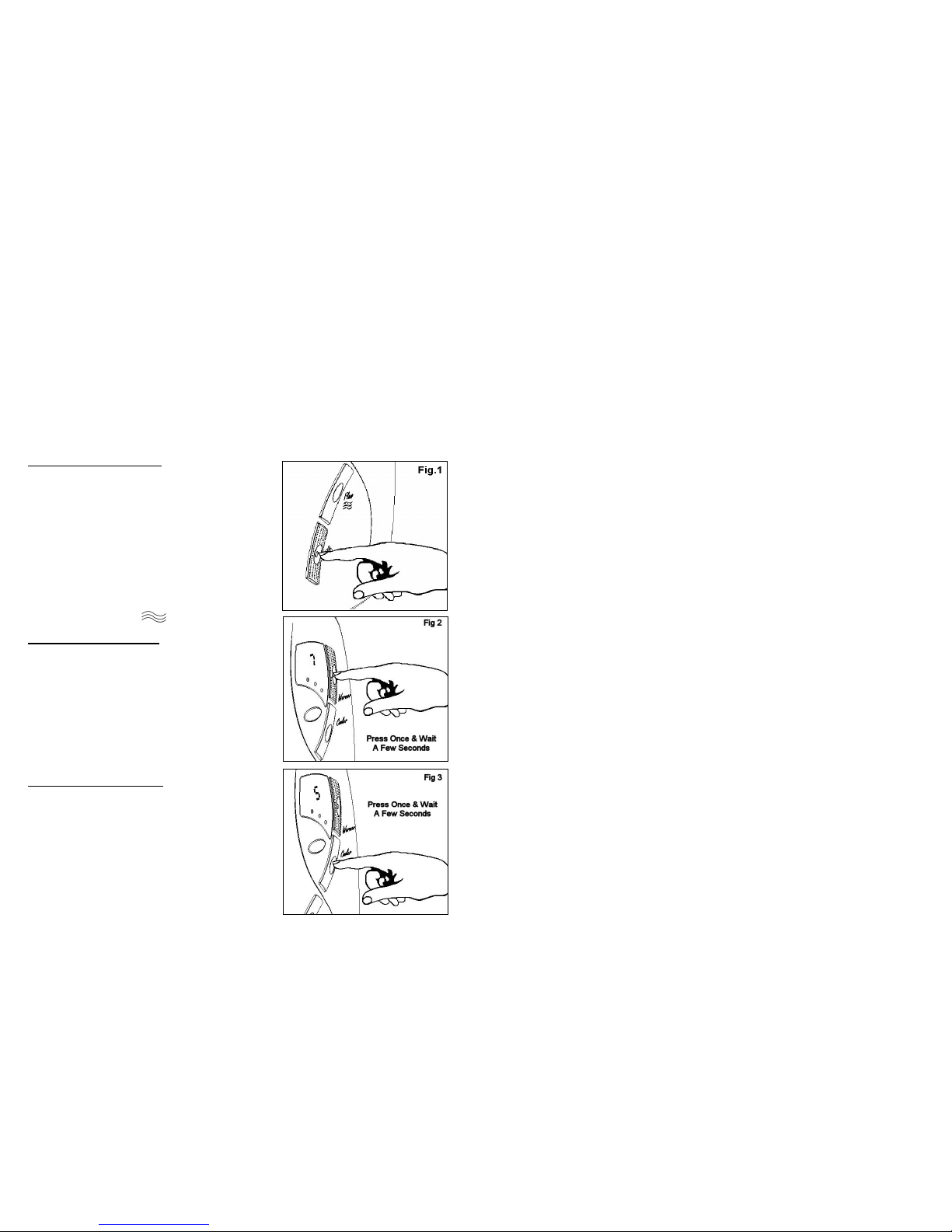
a)Watertoo HOT Pressthe coolerbutton.
Clean sprayplate holes.
b)Watertoo COLD Pressthe warmerbutton.
c)Spray pattern poor Clean sprayplate.
Select outer/ inneronly
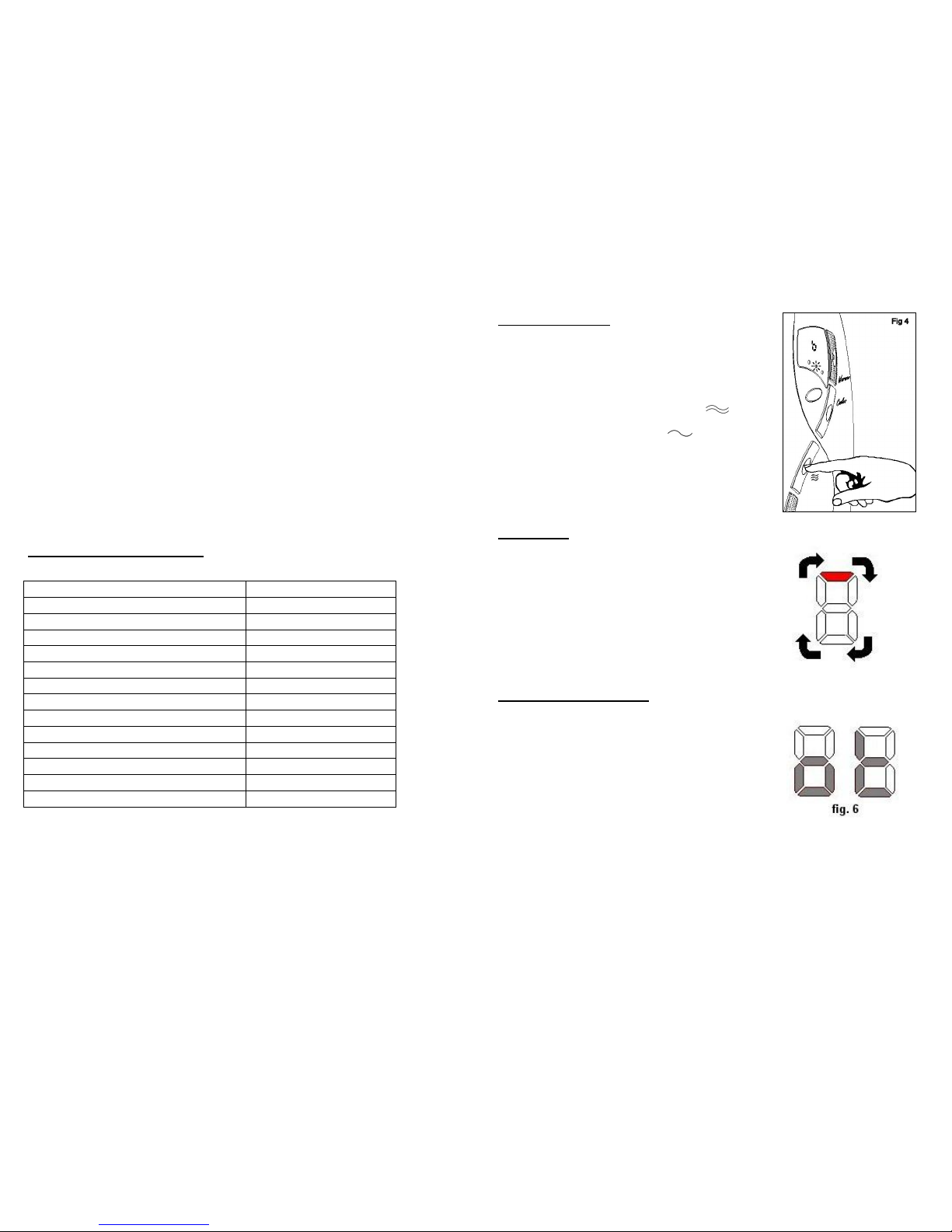
d)Display behaves erratically
Switch off electricityat ceiling / isolatingswitch,waita
few seconds,switch onagain.
(Note the shower should be switchedoff each timeafter
use attheceiling switch.)
e)Waterdoesnot flow when start/stop
buttonispressed
lights on
“o” and then “t” flashing in display
no lights
Note: If there isno waterflowing then theshowerwill
automaticallyswitch off afterabout5 seconds.
Check the watersupply isturned on.
Unit in over temperature mode see section on “purging”
Check ceiling switch ison. Check power ison.
f) Warmer/ cooler buttons only adjusts
between 2 and 5 See relevantsection inprofessional help
g)Unitmakes a whirring noise,
especially at the start of the shower
session.
Thisisnormal. There isa motor insidetheshower used
to adjust the flow and this alwaysoperatesat the start
of each shower.
7
Professional Service Check List
Thisadditional checklist isprovided forthe benefitof the qualified service representative.
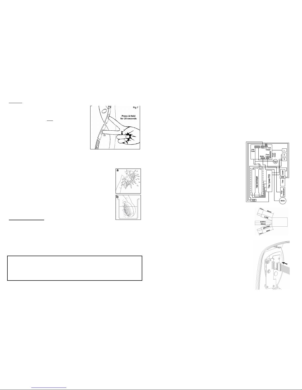
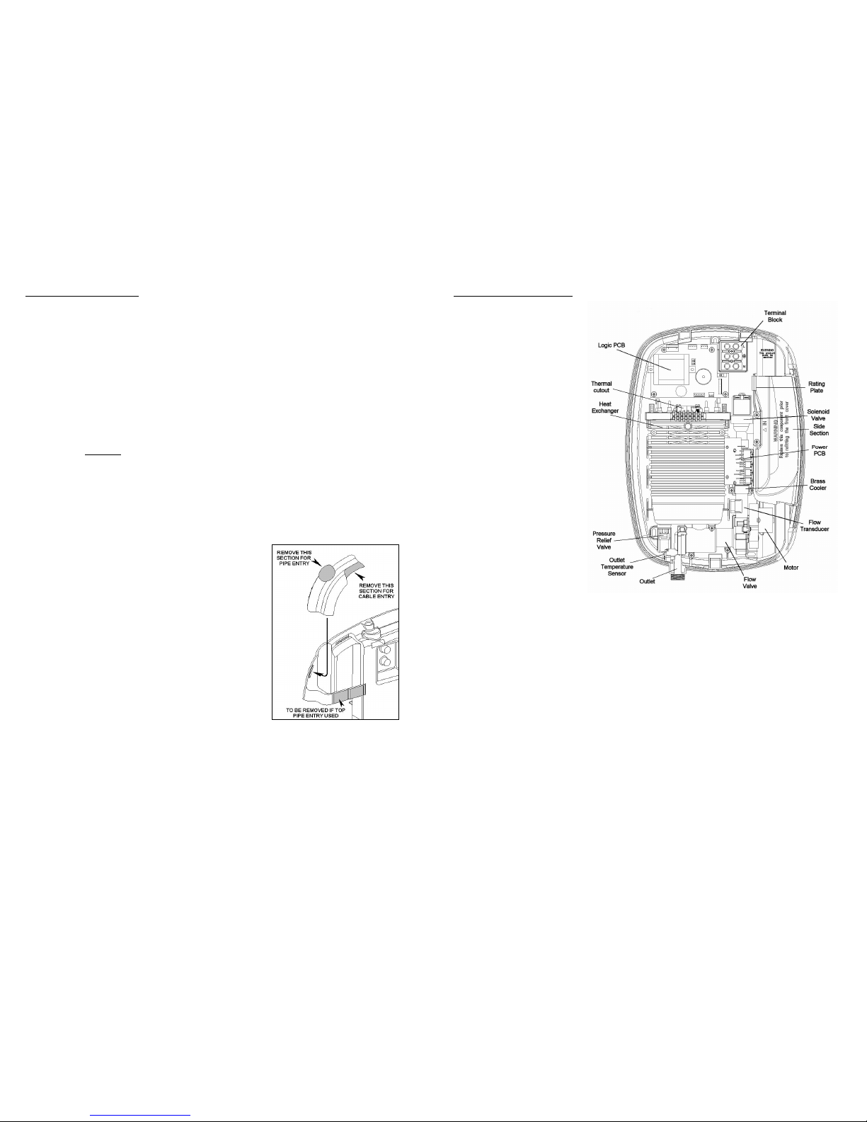
Warning. Switch Off The ElectricityAtThe Isolating Switch Before Removing
The Front Cover ToMake Checks.
a)Poortemperature control
Check inlet /outlet thermistors to see if theyarein
circuit.
Check forblockagein filter of solenoid valve
Check board configuration for correctpower rating
b)Watertoo COLD
Check circuitthrough thermal cut-out
Check circuitthrough all 4elements.
Test should be done using a low voltage resistance
meterwhilst the power isswitchedoff at theisolating
switch
Check circuitthrough triacs
Check working voltage
c)Poororno control over waterflow Replaceinletvalve assembly
d)No water when start button is
pressed.
Check watersupply.
Check circuitthrough solenoid coil.
Ifok replace logic PCB
e)Unithas been switched off using stop
button but canbe heard heatingthe
water Replacetriac PCB
f) Pressurerelief valve operated Check forcause of high pressure and remove it.
Replacepressurerelief valve (Not covered under
guarantee).
g)Temperature buttonsonlyadjust
between 2 and 5 ContactCustomer service
h)Shower runs for about 5secondsand
then switches off byitself
Flow transducer fault.
Check that internal blade “spins”when the water flows :
Ifnot, replacetransducer.

Other Creda Plumbing Product manuals

Creda BRISBANE 8.5 kW User manual

Creda

Creda BRISBANE 8.5 kW User manual

Creda Spa100 User manual

Creda

Creda Spa100 User manual

Creda Power Shower User manual

Creda

Creda Power Shower User manual

Creda JETSPA CONTEMPORARY User manual

Creda

Creda JETSPA CONTEMPORARY User manual

Creda Aquawave White User manual

Creda

Creda Aquawave White User manual

Creda SPA 200c User manual

Creda

Creda SPA 200c User manual

Creda EXPRESSIONS 500S User manual

Creda

Creda EXPRESSIONS 500S User manual

Creda FLORIDA PLUS User manual

Creda

Creda FLORIDA PLUS User manual

Creda Pumped User manual

Creda

Creda Pumped User manual

Creda Shower SPA User manual

Creda

Creda Shower SPA User manual

Creda Spa300c User manual

Creda

Creda Spa300c User manual

Creda PW E4ZC Manual

Creda

Creda PW E4ZC Manual

Creda Florida Spa User manual

Creda

Creda Florida Spa User manual

Creda 570 User manual

Creda

Creda 570 User manual

Creda 550C User manual

Creda

Creda 550C User manual

Creda AquaNoir User manual

Creda

Creda AquaNoir User manual

Creda AQUABLUE User manual

Creda

Creda AQUABLUE User manual

Creda Thermostatic Power Shower User manual

Creda

Creda Thermostatic Power Shower User manual

Popular Plumbing Product manuals by other brands

Viega Prevista 8524.19 Instructions for use

Viega

Viega Prevista 8524.19 Instructions for use

SaunaFin Luna Cedar Assembly instructions

SaunaFin

SaunaFin Luna Cedar Assembly instructions

Sterling Plumbing Shower Receptor and Wall Surround with Backer Boards... Specification sheet

Sterling Plumbing

Sterling Plumbing Shower Receptor and Wall Surround with Backer Boards... Specification sheet

Jacuzzi J-DREAM 90 owner's manual

Jacuzzi

Jacuzzi J-DREAM 90 owner's manual

Black & Decker Price Pfister Classic WKP-6 manual

Black & Decker

Black & Decker Price Pfister Classic WKP-6 manual

Bradley Express SS-2N/BIR3/STD Installation

Bradley

Bradley Express SS-2N/BIR3/STD Installation

Garantia SUPRA-Filter Intern Installation and maintenance instructions

Garantia

Garantia SUPRA-Filter Intern Installation and maintenance instructions

ProFlo PFXCM1M206 installation instructions

ProFlo

ProFlo PFXCM1M206 installation instructions

Hans Grohe Metris 230 Series Instructions for use

Hans Grohe

Hans Grohe Metris 230 Series Instructions for use

emaux EM4411 Manual Installation

emaux

emaux EM4411 Manual Installation

BELLOSTA aperio 2705/S Installation instruction

BELLOSTA

BELLOSTA aperio 2705/S Installation instruction

Sanela SLU 36B Instructions for use

Sanela

Sanela SLU 36B Instructions for use

SUMERAIN S1248CW installation guide

SUMERAIN

SUMERAIN S1248CW installation guide

MX Square Thermostatic Douche Bidet Kit user manual

MX

MX Square Thermostatic Douche Bidet Kit user manual

Hans Grohe Axor UNO Instructions for use/assembly instructions

Hans Grohe

Hans Grohe Axor UNO Instructions for use/assembly instructions

Omnires SYSY36GLB Installation and Maintenance

Omnires

Omnires SYSY36GLB Installation and Maintenance

Smiths John Crane Isomag MAGNUM-P V6S installation guide

Smiths

Smiths John Crane Isomag MAGNUM-P V6S installation guide

SYR HygBox Connect Assembly, Commissioning, Operation and Maintenance Manual

SYR

SYR HygBox Connect Assembly, Commissioning, Operation and Maintenance Manual

manuals.online logo
manuals.online logoBrands
  • About & Mission
  • Contact us
  • Privacy Policy
  • Terms and Conditions

Copyright 2025 Manuals.Online. All Rights Reserved.