manuals.online logo
Brands
  1. Home
  2. •
  3. Brands
  4. •
  5. Crestron
  6. •
  7. Keypad
  8. •
  9. Crestron Horizon HZ-KPCN Series User manual

Crestron Horizon HZ-KPCN Series User manual

HZ-KPCN
Horizon™ Keypads
Installation Guide
Description
Crestron®Horizon™ HZ-KPCN-series precision keypads provide optimal control of
Crestron devices such as lighting, shading, and A/V equipment from a single location.
Each keypad offers up to ve tactile button or rocker switch positions, multicolor LED
backlighting, laser-engraved buttons and customizable faceplates designed to meet your
needs. Simply connect the keypad directly to your Cresnet®control network to begin.
Additional Resources
Visit the product page on the Crestron website (www.crestron.com)
for additional information and the latest rmware updates. Use a QR
reader application on your mobile device to scan the QR image.
Keypad Installation
NOTE: Before operating the HZ-KPCN, ensure the device is using the latest rmware.
Check for the latest HZ-KPCN rmware at www.crestron.com/rmware. Load the
rmware onto the device using Crestron Toolbox™ software.
The Horizon keypad is designed for installation into a standard, single-gang electrical box.
For larger applications, combine up to four keypads in a multi-gang electrical box.
To install the keypad:
1. Turn the system power off.
2. Place the backplate over the rear of the keypad.
NOTE: Crestron recommends installing all keypads with the included backplate
for a more precise, consistent installation. However, when installing keypads in
retrot electrical boxes, the backplate may be omitted.
3. Wire the keypad, connecting to the NET and INPUT ports as needed.
INPUT:
From contact closure or
non-system occupancy
sensor (e.g., GLS-ODT-C-NS).
NET:
Communications from control
system or daisy-chained
Cresnet device.
NET:
To daisy-chained Cresnet®
network device.
4. Fold wires carefully into the back of the electrical box. Avoid pinched wires.
5. Position the keypad in the electrical box with the TOP label properly oriented and
secure the device to the electrical box using the provided screws.
CAUTION: Do not overtighten the screws when attaching the keypad to the
electrical box, damage to the unit and undesired functionality may occur.
Top and
bottom trim
Keypad
Faceplate
Backplate
Drywall
Electrical box
6. Attach the magnetic trim plates to the top and bottom of the faceplate.
7. Ensure all buttons actuate without sticking.
8. Restore the system power.
Button Congurations
The keypad button layout is congurable to suit a wide range of uses. Each keypad
includes ve standard button positions, which may include a single pushbutton or
horizontal rocker switch cap. Larger vertical rocker switches are also available. All buttons
are intended to be laser-engraved to identify each button’s function.
The HZ-KPCN offers the following button-cap congurations:
Five Buttons:
HZ-BTN-1 or
HZ-BTN-RKR1
Three Buttons:
HZ-BTN-1 or HZ-BTN-RKR1 and
HZ-BTN-RKR3
One Button:
HZ-BTN-RKR5
• HZ-BTN-1: One-row button cap, center press (supplied - qty. 5)
• HZ-BTN-RKR1: One-row rocker button cap, left/right press (not supplied)
• HZ-BTN-RKR3: Three-row rocker button cap, top/bottom press (not supplied)
• HZ-BTN-RKR5: Five-row rocker button cap, top/bottom press (not supplied)
To replace keypad buttons:
1. Insert the at end of the spudger tool between the button cap and the keypad near
the left edge of the button. Rotate the spudger tool clockwise to remove the left side
of the button cap.
2. Insert the at end of the spudger tool between the button cap and the keypad near
the right edge of the button. Rotate the spudger tool counterclockwise to remove the
right side of the button cap.
Spudger tool
3. Align the posts on the back of the new button cap with the slot in the keypad and
press rmly onto the keypad. Ensure that the button cap actuates without sticking.
Ambient Light Sensor Calibration
Behind each button is an LED backlight, which illuminates the engraving. The ambient light
sensor adjusts the keypad’s backlight brightness according to the light level in the room.
Once the custom, laser-engraved buttons are installed, calibrate the ambient light sensor.
NOTE: The LED backlight is enabled after light sensor calibration.
To calibrate the light sensor:
1. Ensure the faceplate and bottom trim piece are installed correctly. Remove the top
trim piece.
2. Press and hold the setup button using the pointed end of the supplied spudger tool
until all keypad backlights ash magenta (about 2 seconds).
3. Avoid blocking the light sensor. The light sensor should remain unobstructed and
free of direct light. After about 5 seconds, the calibration process is complete. The
keypad returns to normal operation.
Setup
button
Backlight Customization
To change the color of the LED backlights:
1. Press the setup button once using the pointed end of the spudger tool. The LED
backlights will light brightly for 15 seconds.
2. Press the setup button repeatedly to cycle through the backlight color options.
NOTE: Custom color themes may be dened in the control system program.
Scan the QR
code to view a
video tutorial of
the button cap
replacement
process.
Specications
SPECIFICATION DETAILS
Power Requirements
Cresnet Power Usage
Power Consumption
2 W (83 mA @ 24 VDC)
2 W maximum
INPUT Port (2) digital/analog input ports (referenced to GND);
Digital Input: Rated for 0-24 Volts DC, input impedance
200k Ohms, logic threshold 1.24 Volts DC;
Analog Input: Rated for 0-10 Volts DC, protected to
24 Volts DC maximum, input impedance 200k Ohms;
Programmable 3 Volts, 2k Ohms pull-up resistor per input
Environmental
Temperature
Humidity
Heat Dissipation
32º to 104 ºF (0º to 40 ºC)
10% to 90% RH (non-condensing)
6.8 Btu/h maximum
Dimensions
3-9/32 in
(83 mm)
4-1/8 in
(105 mm)
1-13/16 in
(46 mm)
3-1/16 in
(78 mm)
4-23/32 in
(120 mm)
15/16 in
(24 mm)
5/8 in
(16 mm)
2-23/32 in
(69 mm)
3/8 in
(10 mm)
1-3/4 in
(44 mm)
Setup
button
Light
sensor
Troubleshooting
The following table provides corrective action for possible trouble situations. If further
assistance is required, please contact a Crestron Customer service representative.
Symptom Issue Action
No action is
performed when a
button on the keypad
is pressed.
The unit is not receiving
24 VDC Power.
Check wiring for 24 VDC power.
There is an error in the
control system program.
Verify that the control system
program is correct.
The LEDs do not
light.
The LEDs are not enabled. Perform Light Sensor Calibration
to enable the LEDs.
The keypad button(s)
do not actuate when
pressed.
The keypad mounting
screws are overtightened.
Slightly loosen the mounting
screws.
The button may not be
snapped into the keypad.
Ensure that the button cap is
properly oriented and installed.
The backlight LEDs
are too bright when
the room is dark.
The keypad may be
staying in Day mode. While
in Day mode the LEDs are
typically full brightness
or off.
Check the DayNightThreshold
setting in the control system
program. If set to Default, rerun
the calibration process from the
keypad.
Change the DayNightThreshold
Calibration setting to Med-Bright
or Bright in the control system
program to ensure Night mode is
entered when the room is dark.
The LED brightness
settings for Night mode
may be incorrect.
Adjust the Keypad Brightness
settings in control system
program.
The backlight LEDs
are too dim or not
visible.
The keypad may be
staying in Night mode
as the room transitions
from Dark to Dim. While
in Night mode the LEDs
are typically at very low
brightness.
Change the DayNightThreshold
Calibration setting to Med-Dark
or Dark in the control system
program to ensure Day mode is
entered when the room brightens.
Calibration may have been run
when the lower trim piece was not
installed. Replace lower trim and
rerun calibration.
Federal Communications Commission (FCC) Compliance Statement
This device complies with part 15 of the FCC Rules. Operation is subject to the following
conditions:(1) This device may not cause harmful interference and (2) this device must accept any
interference received, including interference that may cause undesired operation.
CAUTION: Changes or modications not expressly approved by the manufacturer responsible for
compliance could void the user’s authority to operate the equipment.
NOTE: This equipment has been tested and found to comply with the limits for a Class B digital
device, pursuant to part 15 of the FCC Rules. These limits are designed to provide reasonable
protection against harmful interference in a residential installation. This equipment generates,
uses and can radiate radio frequency energy and, if not installed and used in accordance with the
instructions, may cause harmful interference to radio communications. However, there is no guarantee
that interference will not occur in a particular installation. If this equipment does cause harmful
interference to radio or television reception, which can be determined by turning the equipment off
and on, the user is encouraged to try to correct the interference by one or more of the following
measures:
• Reorient or relocate the receiving antenna.
• Increase the separation between the equipment and receiver.
• Connect the equipment into an outlet on a circuit different from that to which the receiver is
connected.
• Consult the dealer or an experienced radio/TV technician for help.
Industry Canada (IC) Compliance Statement
CAN ICES-3 (B)/NMB-3(B)
The product warranty can be found at www.crestron.com/warranty.
The specic patents that cover Crestron products are listed at www.crestron.com/legal/patents.
Certain Crestron products contain open source software. For specic information, please visit
www.crestron.com/opensource.
Crestron, the Crestron logo, Crestron Toolbox, Cresnet, and Horizon are either trademarks or
registered trademarks of Crestron Electronics, Inc. in the United States and/or other countries. Other
trademarks, registered trademarks, and trade names may be used in this document to refer to either
the entities claiming the marks and names or their products. Crestron disclaims any proprietary
interest in the marks and names of others. Crestron is not responsible for errors in typography or
photography.
This document was written by the Technical Publications department at Crestron.
©2018 Crestron Electronics, Inc.
Crestron Electronics, Inc. Installation Guide - DOC. 8285A
15 Volvo Drive, Rockleigh, NJ 07647 (2051306)
Tel: 888.CRESTRON 06.18
Fax: 201.767.7576 Specications subject to
www.crestron.com change without notice.
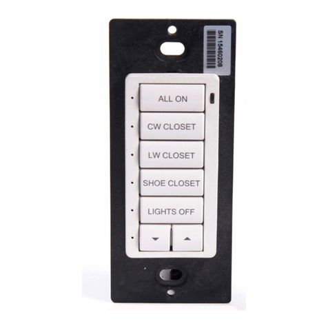
This manual suits for next models

4

Other Crestron Keypad manuals

Crestron HZ-BTN User manual

Crestron

Crestron HZ-BTN User manual

Crestron INET-CBDEX-E Original operating instructions

Crestron

Crestron INET-CBDEX-E Original operating instructions

Crestron Cameo INET-CBDEX Series How to use

Crestron

Crestron Cameo INET-CBDEX Series How to use

Crestron Cameo C2NI-CB Series How to use

Crestron

Crestron Cameo C2NI-CB Series How to use

Crestron C2N-LCDB3 Dimensional drawing

Crestron

Crestron C2N-LCDB3 Dimensional drawing

Crestron Horizon infiNET EX HZ-KPEX User manual

Crestron

Crestron Horizon infiNET EX HZ-KPEX User manual

Crestron C2NI-AG Creslight II How to use

Crestron

Crestron C2NI-AG Creslight II How to use

Crestron Cameo C2NI-CB Series User manual

Crestron

Crestron Cameo C2NI-CB Series User manual

Crestron AirMedia ZUMMESH-KP10AMBATT User manual

Crestron

Crestron AirMedia ZUMMESH-KP10AMBATT User manual

Crestron ZUMLINK-KP User manual

Crestron

Crestron ZUMLINK-KP User manual

Crestron Cameo C2N-CBD How to use

Crestron

Crestron Cameo C2N-CBD How to use

Crestron black nova AXES Series User manual

Crestron

Crestron black nova AXES Series User manual

Crestron CNX-B12 How to use

Crestron

Crestron CNX-B12 How to use

Crestron CN-WP12FW User manual

Crestron

Crestron CN-WP12FW User manual

Crestron HTT-B2EX-BATT User manual

Crestron

Crestron HTT-B2EX-BATT User manual

Crestron CLWI-KPLEX User manual

Crestron

Crestron CLWI-KPLEX User manual

Crestron CNX-BF12 How to use

Crestron

Crestron CNX-BF12 How to use

Crestron ZUM  ZUMMESH-KP User manual

Crestron

Crestron ZUM ZUMMESH-KP User manual

Crestron Cameo C2N-CBD-P Original operating instructions

Crestron

Crestron Cameo C2N-CBD-P Original operating instructions

Crestron HTT-B10EX How to use

Crestron

Crestron HTT-B10EX How to use

Crestron CNWM-10A User manual

Crestron

Crestron CNWM-10A User manual

Crestron Zum Series User manual

Crestron

Crestron Zum Series User manual

Crestron C2N-DB12 How to use

Crestron

Crestron C2N-DB12 How to use

Crestron Cameo C2N-CBD-P Quick start guide

Crestron

Crestron Cameo C2N-CBD-P Quick start guide

Popular Keypad manuals by other brands

Bosch D202A Series Technical specifications

Bosch

Bosch D202A Series Technical specifications

Genie Wireless Keypad-IC Installation and programming instructions

Genie

Genie Wireless Keypad-IC Installation and programming instructions

Conlan C1000 user manual

Conlan

Conlan C1000 user manual

Maxkin KP-A1 user manual

Maxkin

Maxkin KP-A1 user manual

ADEMCO 6150PL3 installation guide

ADEMCO

ADEMCO 6150PL3 installation guide

Satel INT-TSG Quick installation guide

Satel

Satel INT-TSG Quick installation guide

Gecko in.k300 user manual

Gecko

Gecko in.k300 user manual

Alarm Controls Corporation KP-300 operating instructions

Alarm Controls Corporation

Alarm Controls Corporation KP-300 operating instructions

Linear AM-KPI installation instructions

Linear

Linear AM-KPI installation instructions

Lumi IML Connector user manual

Lumi

Lumi IML Connector user manual

alpro AS-ATP2S200 instructions

alpro

alpro AS-ATP2S200 instructions

Nortek Security & Control 2GIG 2GIG-PAD1-345 installation instructions

Nortek Security & Control

Nortek Security & Control 2GIG 2GIG-PAD1-345 installation instructions

Eldes EKB3 installation guide

Eldes

Eldes EKB3 installation guide

ICT PRT-TS50 user manual

ICT

ICT PRT-TS50 user manual

LEGRAND On Q lyriQ Instruction

LEGRAND

LEGRAND On Q lyriQ Instruction

SILENTRON 5528 HT manual

SILENTRON

SILENTRON 5528 HT manual

urmet domus 1156/10 Programming guide

urmet domus

urmet domus 1156/10 Programming guide

Dorma AC217 installation instructions

Dorma

Dorma AC217 installation instructions

manuals.online logo
manuals.online logoBrands
  • About & Mission
  • Contact us
  • Privacy Policy
  • Terms and Conditions

Copyright 2025 Manuals.Online. All Rights Reserved.