manuals.online logo
Brands
  1. Home
  2. •
  3. Brands
  4. •
  5. Crestron
  6. •
  7. Switch
  8. •
  9. Crestron DigitalMedia DM-MD6X1 User manual

Crestron DigitalMedia DM-MD6X1 User manual

Other manuals for DigitalMedia DM-MD6X1

1

Other Crestron Switch manuals

Crestron HD-MD4X2-4KZ-E User manual

Crestron

Crestron HD-MD4X2-4KZ-E User manual

Crestron DigitalMedia DM-MD8X8-CPU3 User manual

Crestron

Crestron DigitalMedia DM-MD8X8-CPU3 User manual

Crestron DigitalMedia XiO Director DM-XIO-DIR-160 Dimensional drawing

Crestron

Crestron DigitalMedia XiO Director DM-XIO-DIR-160 Dimensional drawing

Crestron CNLGE-8 User manual

Crestron

Crestron CNLGE-8 User manual

Crestron DigitalMedia DM-MD8X8-CPU3 User manual

Crestron

Crestron DigitalMedia DM-MD8X8-CPU3 User manual

Crestron CLW-SLVS1W User manual

Crestron

Crestron CLW-SLVS1W User manual

Crestron HD-RX-4K-510-C-E User manual

Crestron

Crestron HD-RX-4K-510-C-E User manual

Crestron 8x8 DigitalMedia DM-MD8X8 User manual

Crestron

Crestron 8x8 DigitalMedia DM-MD8X8 User manual

Crestron DigitalMedia DM-MD64X64 Dimensional drawing

Crestron

Crestron DigitalMedia DM-MD64X64 Dimensional drawing

Crestron Green Light GL-IPAC-SW8 User manual

Crestron

Crestron Green Light GL-IPAC-SW8 User manual

Crestron GreenLight DIN-8SW8 How to use

Crestron

Crestron GreenLight DIN-8SW8 How to use

Crestron GreenLight DIN-8SW8 How to use

Crestron

Crestron GreenLight DIN-8SW8 How to use

Crestron DIN-8SW8-I User manual

Crestron

Crestron DIN-8SW8-I User manual

Crestron DM NVX Director DM-NVX-DIR Series User manual

Crestron

Crestron DM NVX Director DM-NVX-DIR Series User manual

Crestron GREEN LIGHT GLPX-HSW-FT User manual

Crestron

Crestron GREEN LIGHT GLPX-HSW-FT User manual

Crestron QM-WMC How to use

Crestron

Crestron QM-WMC How to use

Crestron HD-RX-4K-510-C-E User manual

Crestron

Crestron HD-RX-4K-510-C-E User manual

Crestron DM-MD8X1-4K-C User manual

Crestron

Crestron DM-MD8X1-4K-C User manual

Crestron Sonnex SWE-8 User manual

Crestron

Crestron Sonnex SWE-8 User manual

Crestron DigitalMedia DM-MD6X1 User manual

Crestron

Crestron DigitalMedia DM-MD6X1 User manual

Crestron DM Lite HD-RX-4K-510-C-E User manual

Crestron

Crestron DM Lite HD-RX-4K-510-C-E User manual

Crestron ZUM-FLOOR-HUB Dimensional drawing

Crestron

Crestron ZUM-FLOOR-HUB Dimensional drawing

Crestron HD-RX-201-C-E Dimensional drawing

Crestron

Crestron HD-RX-201-C-E Dimensional drawing

Crestron 8x8 DigitalMedia DM-MD8X8 User manual

Crestron

Crestron 8x8 DigitalMedia DM-MD8X8 User manual

Popular Switch manuals by other brands

SMC Networks SMC6224M Technical specifications

SMC Networks

SMC Networks SMC6224M Technical specifications

Aeotec ZWA003-S operating manual

Aeotec

Aeotec ZWA003-S operating manual

TRENDnet TK-209i Quick installation guide

TRENDnet

TRENDnet TK-209i Quick installation guide

Planet FGSW-2022VHP user manual

Planet

Planet FGSW-2022VHP user manual

Avocent AutoView 2000  AV2000BC AV2000BC Installer/user guide

Avocent

Avocent AutoView 2000 AV2000BC AV2000BC Installer/user guide

Moxa Technologies PT-7728 Series user manual

Moxa Technologies

Moxa Technologies PT-7728 Series user manual

Intos Electronic inLine 35392I operating instructions

Intos Electronic

Intos Electronic inLine 35392I operating instructions

Cisco Catalyst 3560-X-24T Technical specifications

Cisco

Cisco Catalyst 3560-X-24T Technical specifications

Asante IntraCore IC3648 Specifications

Asante

Asante IntraCore IC3648 Specifications

Siemens SIRIUS 3SE7310-1AE Series Original operating instructions

Siemens

Siemens SIRIUS 3SE7310-1AE Series Original operating instructions

Edge-Core DCS520 quick start guide

Edge-Core

Edge-Core DCS520 quick start guide

RGBLE S00203 user manual

RGBLE

RGBLE S00203 user manual

Thrustmaster FLIGHT SIMULATOR X quick guide

Thrustmaster

Thrustmaster FLIGHT SIMULATOR X quick guide

Southwire SURGE GUARD 41390 RVC troubleshooting guide

Southwire

Southwire SURGE GUARD 41390 RVC troubleshooting guide

Buhler Nivotemp NT 61 Brief instructions

Buhler

Buhler Nivotemp NT 61 Brief instructions

Kramer VS-41HDCP user manual

Kramer

Kramer VS-41HDCP user manual

Techly IDATA AU-270 user manual

Techly

Techly IDATA AU-270 user manual

Belkin F1U109 user manual

Belkin

Belkin F1U109 user manual

manuals.online logo
manuals.online logoBrands
  • About & Mission
  • Contact us
  • Privacy Policy
  • Terms and Conditions

Copyright 2025 Manuals.Online. All Rights Reserved.

1
quickstart guide
DM-MD6X1
www.crestron.com
888.273.7876 201.767.3400
©2010 Specifications subject to
change without notice.
For details, refer to the latest revision of the DM-MD6X1 DigitalMedia™
Switcher Operations Guide, Doc. 6850.
QUICKSTART DOC. 6851B (2024731) 06.10
DigitalMedia™Switcher
All brand names, product names, and trademarks
are the property of their respective owners.
DM-MD6X1
1Before Starting
2
3
!CAUTION: Do not connect power cords until instructed to do so.
NOTE: Before beginning any of these QuickStart procedures, make
certain that all DigitalMedia
™
cables are installed throughout the home.
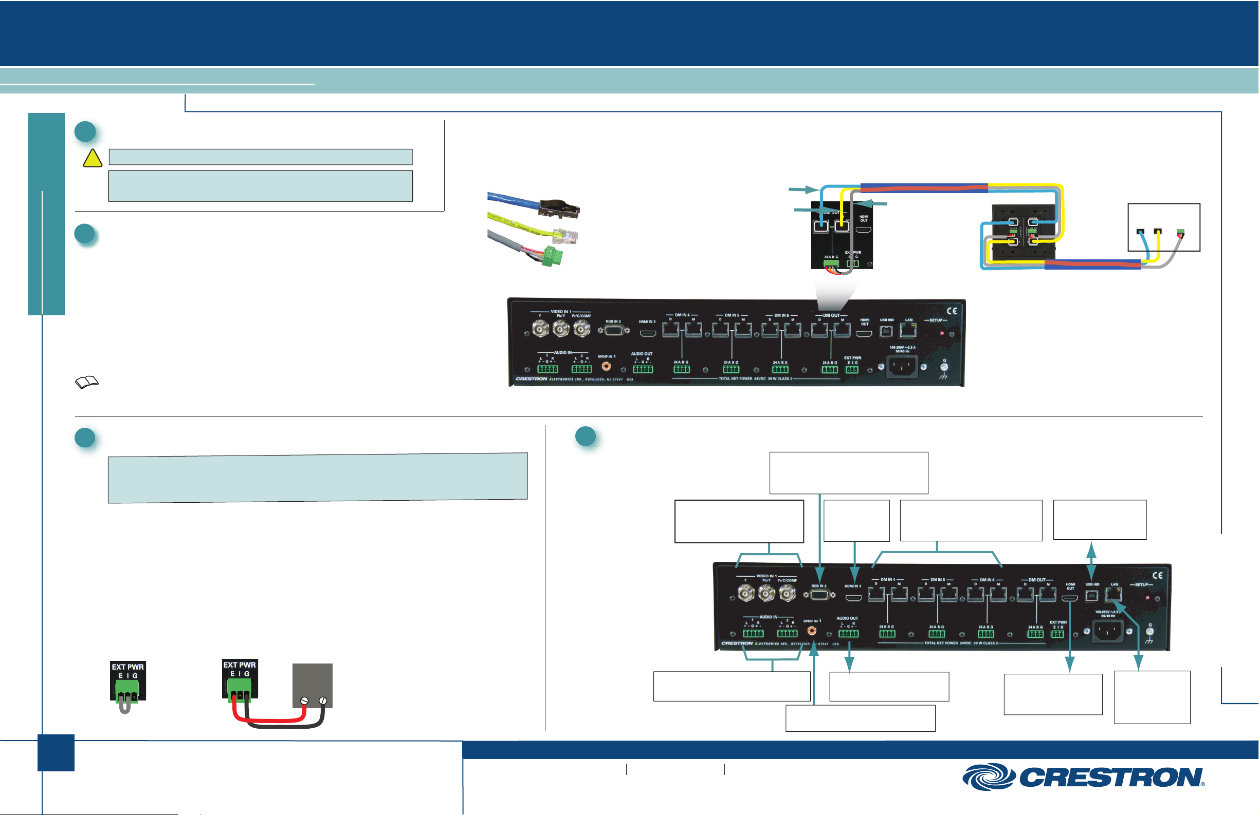
Connect DigitalMedia Room Controllers and Repeaters
A. Using a DigitalMedia™cable (DM-CBL-P or DM-CBL-NP), connect the
switcher output directly to a DM-RMC-100 Room Controller, or, if required,
first connect to a DM-DR Repeater and then connect the output of the
DM-DR to a DM-RMC-100. The illustration immediately to the right shows
the special connectors used for the three cables contained within the
DigitalMedia cable. The illustration at the far right shows a typical wiring
configuration for the switcher’s single DM output port. (The output can
support a maximum of up to three repeaters and one room controller.)
B. For detailed instructions on operation and setup of the DM-DR
Repeater and the DM-RMC-100 Room Controller, refer to the latest
version of their respective Operations & Installation Guides (Doc. 6745
and Doc. 6743).
DM-CBL-P
or
DM-CBL-NP
DM-DR
Repeater
Room Controller
DM-CBL-P
or
DM-CBL-NP
‘D’ Video
‘M’ Data
Management ‘DMNet’
Control &
Power
‘D’ Video
‘DMNet’ Control & Power
‘M’ Data Management (CAT5E)
Connect DigitalMedia Device Power Source
24 VDC
+ G
A. The switcher can supply up to 30 watts of internal power to connected room
controllers repeaters and transmitters up to their rated level.
B. Ensure that the EIG jumpers are installed and wired between Eand Ifor internal
power to be routed to the connected devices. If power is not being supplied to an external
device, make sure the jumper is not connected.
C. If the devices to be connected (both input and output) will require more power than is
available from the switcher, connect them to an external 24 VDC supply (that can supply
the required power) by connecting the Eand Gterminals of the EIG connector to the +
and Gterminals of the (unpowered) external supply. (Refer to the illustration.)
EXTERNAL
POWER SUPPLY
INTERNAL
POWER
4Connect Other Inputs and Outputs
:
:
DM Input
D M 24ABG
RGB IN 2:
From Analog and Component Video
Input Sources
NOTE: Before beginning any of these QuickStart procedures, make
certain that all DigitalMedia
™
cables are installed throughout the home.
NOTE: Before beginning any of these QuickStart procedures, make
certain that all DigitalMedia
™
cables are installed throughout the home.
NOTE: Before beginning any of these QuickStart procedures, make
certain that all DigitalMedia
™
cables are installed throughout the home.
NOTE: If a DM switcher, or other DM device supplying power, is connected to a DM IN 4-6 port
of the DM-MD6X1, then the +24V wire between the DM device and the DM-MD6X1 must be
disconnected. The A B G wires must remain connected.
VIDEO IN 1:
From YPbPr, Composite or
S-video Sources
HDMI IN 3:
HDMI Digital
Video/Audio
DM IN / 24 A B G (4-6):
From Outputs of DM Transmitters
or Other DM Devices
USB HID:
To USB HID Device
LAN:
10BASE-T/
100BASE-TX
Ethernet to LAN
HDMI OUT:
HDMI Digital
Video/Audio Output
AUDIO OUT:
Balanced Line Level Audio
SPDIF IN 1:
From Digital Audio Output
AUDIO IN (1-2):
Balanced Line Level Analog Audio
For details, refer to the latest revision of the DM-MD6X1 DigitalMedia™
Switcher Operations Guide, Doc. 6850.
QUICKSTART DOC. 6851B (2024731) 06.10
2
quickstart guide
DM-MD6X1
www.crestron.com
888.273.7876 201.767.3400
©2010 Specifications subject to
change without notice.
DigitalMedia™Switcher
All brand names, product names, and trademarks
are the property of their respective owners.
DM-MD6X1
:
Apply Power
A. Connect the AC power cord to the switcher. Then connect the
power cord to AC power.
B. Connect power to any external 24VDC supplies that were
connected in Section 3.
NOTE: The switcher does not have a power switch. Power is
applied to the unit by plugging in its power cords.
Select Input Sources
Use the front panel controls to route input sources to the output.
A. Press ROUTE, then press the desired INPUTS button to select the signal type(s)
you wish to route. The corresponding LED will light.
B. If necessary, press the RESET button to reboot the unit. All settings are retained.
7Configure the IP Address
The switcher is supplied in DHCP mode and automatically configures the IP
addresses of connected devices.
With a PC connected via USB to the COMPUTER port, use the Crestron
Toolbox™ “System Info” window to set static IP addresses for the transmitter
and room controller or DM switcher. Refer to the Toolbox help file for details.
NOTE: When a PC is connected to the USB port, the USB HID DISABLED
red LED indicates that HID functionality is disabled.
When the switcher is in DHCP mode, all connected transmiters and room
controllers are set to DHCP mode.
When the switcher is in Static mode, all connected transmiters and room
controllers are set to Static mode. Settings are:
+4 for DM4
+5 for DM5
+6 for DM6
+17 for DM OUT
For example, if the switcher is set to 192.168.1.100,
devices connected to DM OUT will be set to 192.168.1.117
ROUTE
6
5
NOTE: Out-of-the-box, if analog audio and digital audio inputs are both connected,
the switcher automatically selects the digital audio for routing. Programming can
allow you to choose between the two input signals.
NOTE: The SYNC LED is valid only for the last routed local source and the DM IN
source.