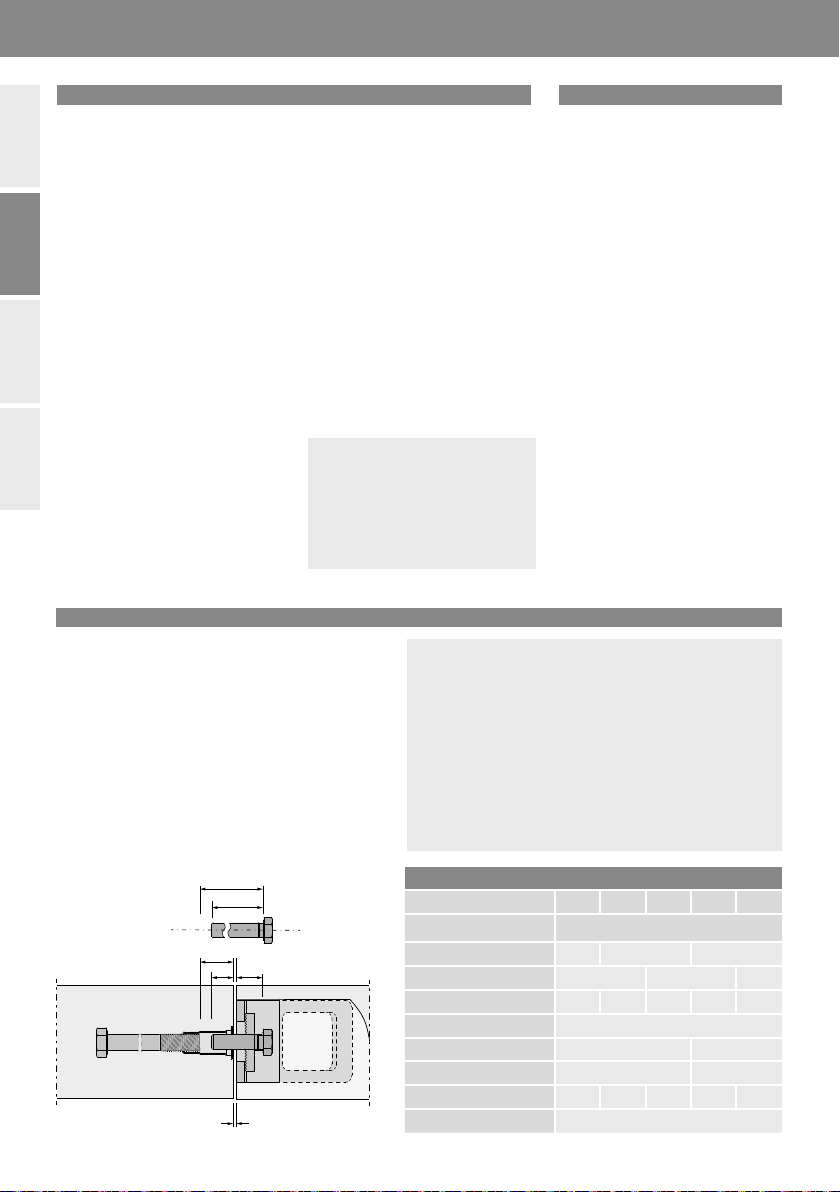
CRH Leviat HALFEN HEK3 User manual

HALFEN HEK3 INST_HEK3 04/23
Assembly Instructions •Montageanleitung•Montagehandleiding•Instrukcja montażu
IN
®
EN Precast coupler
DE Fertigteilverbinder
NL Prefab verbinding
PL Łącznik do prefabry-
katów

HEK3 -T
10mm 20mm 30 mm 40mm
2© 2023 · INST_HEK 04/23 · www.halfen.com
HALFEN HEK3 Assembly Instructions
Deutsch EnglishNederlandsPolski
Recess former with magnets: With removable magnet and fixing
screws, ∅5mm L=30 mm.
Product overview
HEK3-100-T-HDG
Precast coupler
HEK3-100-L-HDG
Precast coupler
Recess former with screw fixing: For fixing the HEK3 Precast coupler
to non-magnetic formwork
Recess former with strong magnet
Incl. 2 screws ∅6mm L=30 mm
For 50mm installation depth in
production processes that demand
a stronger adhesive force.
Incl. 2 screws ∅6mm L=30 mm
Incl. 2 screws ∅6mm L=50 mm
plus 1 screws ∅5mm L=50 mm
for the detachable magnet
Incl. 2 screws ∅6mm L=50 mm
Fixing material: Fixing material, for use with recess formers when fixing HEK3 Precast couplers to non-magnetic formwork.
Optional M10 screw can be used for fixing instead of a M10 threaded rod; supplied by customer!
For easy identification the type HEK3-100-T Precast coupler has a notch at the bottom
edge of the bond-holes as well as the type marking. The notch is also visible when
the precast coupler is fixed to formwork with the recess former.
Type identification
Type marking
Red
Blue
Green

HEK3 -T
HEK3 -T
3
© 2023 · INST_HEK 04/23 · www.halfen.com
HALFEN HEK3 Assembly Instructions
Deutsch English
NederlandsPolski
Product overview
HEK3 selection and preparation
HEK3 CounterplateHEK3 Washers
2 screws ∅6mm
Magnet fixed
with
...for 30–40mm
height adjustment plate use
the supplied L=50mm
∅5mm screws
∅5mm L=30mm
screws
+
HEK3 Shims (only applicable for M16)
Used to shim under couplers
when fixing with sleeve anchor.
Separate verification required.
See also: General information.
Not to scale
HSK HALFEN Bolts
Selecting the correct recess former
Fixing the optional height adjustment plate to the recess former
(example shows a recess former with magnet)
The type of recess former depends on the
material of the formwork and the application
HEK3 + Height-adapter
Wood/plastic
formwork
Remove the
magnet from the
recess former and
insert in the
height adjustment
plate
Replace and tighten
the screws...
Depending on the required installation
depth select the correct height adjustment
plate.
M16
Grease the recess former and
the serrated surface of the HEK3.
Then press the recess former
onto the HEK3.
Grease the assembled recess
former and the serrated surface
of the HEK3. Then press the
recess former onto the HEK3.
Metal formwork
M20
∅17mm 17 mm
∅21 mm
21 mm
5mm
3mm
2mm
Red Blue Green

Ls,min
Ls,max
as
t1,fix
t2,fix
4© 2023 · INST_HEK 04/23 · www.halfen.com
HALFEN HEK3 Assembly Instructions
Deutsch EnglishNederlandsPolski
Determine the required bolt length
General installation notes
The HEK3 Precast coupler must be
installed flush with the surface of a
precast concrete element. Depending
on the type of formwork/concreting
method the appropriate type of HEK3
recess former must be selected for fixing
the precast coupler to the formwork.
It is recommended to use sufficient
grease on both the serrated surface of
the HEK3 and the recess formers; this
simplifies stripping and significantly
increases the service life. After striking
the formwork the HEK3 recess former
is removed; this leaves an installation
access hole on one side of the precast
concrete element.
Care should be taken to keep the
serration in the HEK3 Precast coupler
clean.
The concrete must be poured with care;
avoid direct contact of the concrete
vibrator with the precast coupler.
The precast coupler must only be
subjected to load when the design
concrete strength has been reached.
HEK3 shims must be used between
the fixing anchor and the HEK3
contact surface when installing if
excess space in the joint gap is
present. Bending in the bolt must
be verified for this application.
When installing the bolts, the
tightening torque (TInst) for the
HEK3 Precast coupler as specified
must be observed. The minimum and
maximum screw depths for the fixing
anchor bolts in the sleeve anchor
must also be observed.
Only use bolts as specified in the
design plans as provided by the
responsible engineer to connect the
precast concrete elements.
The precast coupler is anchored
with a bolt in the anchoring element
which was previously cast in the
second concrete element. Bolt and
anchoring element must be selected
and cast in as specified by the
responsible planning engineer.
The required bolt length Lsis subject
to verification.
Required bolt lengths Ls [mm]
Joint (gap) width [mm] 0 5 10 15 20
DEMU Fixing i.e. bolt anchor Bolt lengths
1980-P FV M16 50 55 65
1988 FV M16 50 60 70
T-FIXX GV M16×60 50 55 60 65 70
T-FIXX GV M16×100/125 70
1980-P FV M20 60 70
1988 FV M20 60 70
T-FIXX GV M20×70 60 65 70 75 80
T-FIXX GV M20×100/145 80
All HALFEN HEK Precast couplers
listed in the “Technical catalogue” can
be subjected to welding. Nevertheless,
any welding including tack-welding
may negatively affect the products
characteristic properties. If in excep-
tional cases welding is unavoidable,
the following must be observed:
• heat generation may cause damage
and lower the max. load capacity
• any coatings or covering must be
removed before welding;
appropriate measures must be tak-
en to protect against fumes caused
by the welding process
• mandatory protective equipment
must be worn
• observing any applicable regula-
tions for welding is the responsibility
of the customer
• We do not accept any liability for
damage to Leviat products or
consequential damage, caused by
welding, which is not within the
scope of our own production
process.
Welding
Ls ≥Ls,min
Ls ≤Ls,max
with
Ls,min = s + t1+ t2(minimum bolt length)
Ls,max = a + t1+ t2(maximum bolt length)
s = minimum screw-in depth of the fixing anchor is
according to manufacturer’s specification
a = maximum screw-in depth of the fixing anchor is
according to manufacturer’s specification
t1,fix = clamp thickness of the joint gap
t2,fix = 22 mm (clamp size of the HEK3 Precast coupler with
counterplate and washer)
Observe the installation instructions
included with the HALFEN DEMU
Fixing anchors.
Free Download at www.halfen.com

1
2
3
5
6
4
1
2
HEK3-T
5
64
7
HEK3 -T
HEK3-T
HEK3-T
HEK3 -T
3
HEK3 -T
HEK3 -T
5
© 2023 · INST_HEK 04/23 · www.halfen.com
HALFEN HEK3 Assembly Instructions
Deutsch English
NederlandsPolski
Face-up production in the precast plant (Metal formwork)
Face-down production in the precast plant (Wood/timber formwork)
Measure and mark the exact position
for the HEK3 on the metal formwork.
Grease the serrated surface of the
HEK3 and press on to the recess former;
turn the right way up as illustrated.
Check that all recess formers are at
the specified positions and securely
attached to the formwork.
Tilt-up/raise the precast component
to access the recess former. Screw a
M10 threaded rod in the top of the
recess former for easy removal.
Recess formers in positive cast elements
can be removed before lifting.
Screw a M10 rod in the recess former
for easy removal
(Orientate the magnets towards the
formwork). Place the HEK3 with the
recess former in the exact, specified
position on the formwork.
Fix the correct height adjustment plate
to the recess former for installation
depth > 50mm. see page 3.
Always use ample formwork grease.
Fix the correct adapter to the recess
former or installation depth >50mm.
s. page 3. Always use ample formwork
grease.
Fix the recess formers with the
attached HEK3 Precast coupler to the
formwork with a threaded rod or
10mm bolt.
After the concrete has hardened,
remove the formwork.
Locate the exact position for the HEK3
Precast coupler and drill an 11mm hole
for the fixing rod/bolt in the formwork.
Grease the serrated surface of the
HEK3 Precast coupler and press on to
the recess former.
After the concrete has hardened,
loosen the fixings and remove the
formwork from the component.
Table of contents
Languages:
Other CRH Industrial Equipment manuals

CRH
CRH Leviat HALFEN DETAN-S User manual

CRH
CRH CRL SS96 User manual

CRH
CRH Leviat HALFEN HDB-Z User manual

CRH
CRH Leviat HALFEN DEHA HA-N User manual

CRH
CRH Leviat HALFEN HBB User manual

CRH
CRH Leviat HALFEN MBT User manual

CRH
CRH Leviat HALFEN DEHA 6003 User manual

CRH
CRH Leviat Halfen HCC User manual

CRH
CRH Leviat Ancon 2000 User manual

CRH
CRH Leviat HALFEN PSA User manual