5
© 2020 · INST_DKR 10/20 · www.halfen.com
Deutsch English
DKR Montageanleitung
Polski
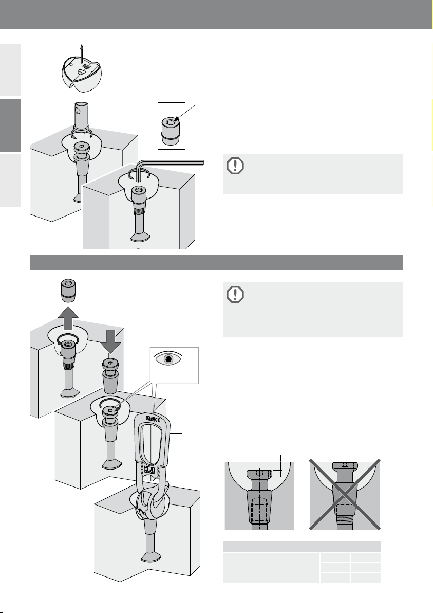
Lastklasse:
Zuordnung:
6173 6153 + 6160
6141
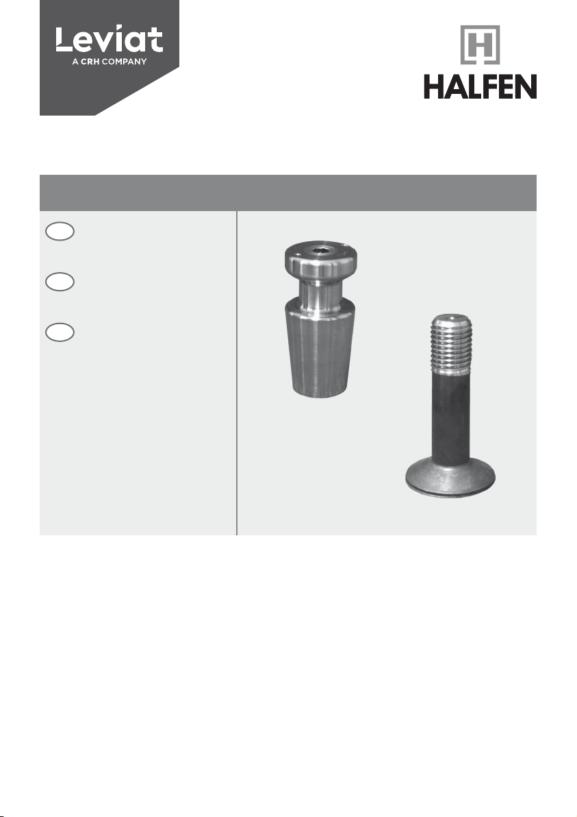
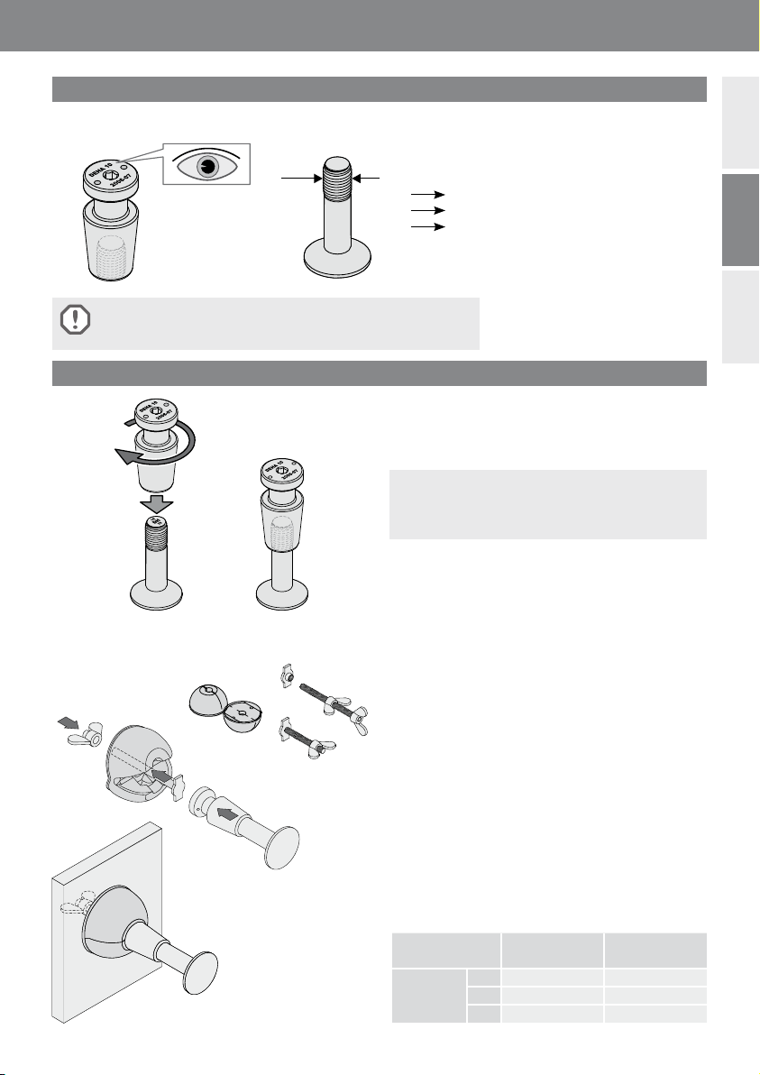
Der DKR-Anker besteht aus zwei Tei-
len, dem Ankerschaft 6003 und dem
wiederverwendbaren Adapterkopf
6004. Für jede Lastklasse gibt es un-
terschiedlich lange Ankerschäfte, die
nach statischen Erfordernissen festge-
legt werden. Für jede Lastklasse gibt
es nur einen Adapterkopf. Anker-
schaft und Adapterkopf sind so kon-
struiert, dass nur die jeweiligen Last-
klassen zusammenpassen. Die Last-
klasse ist auf dem Adapterkopf
aufgeprägt.
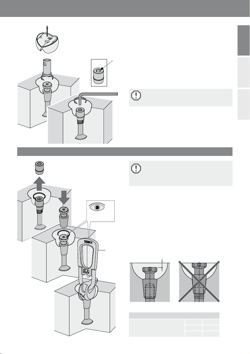
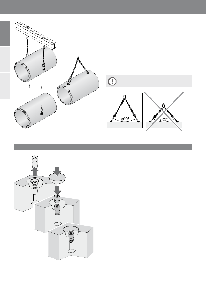
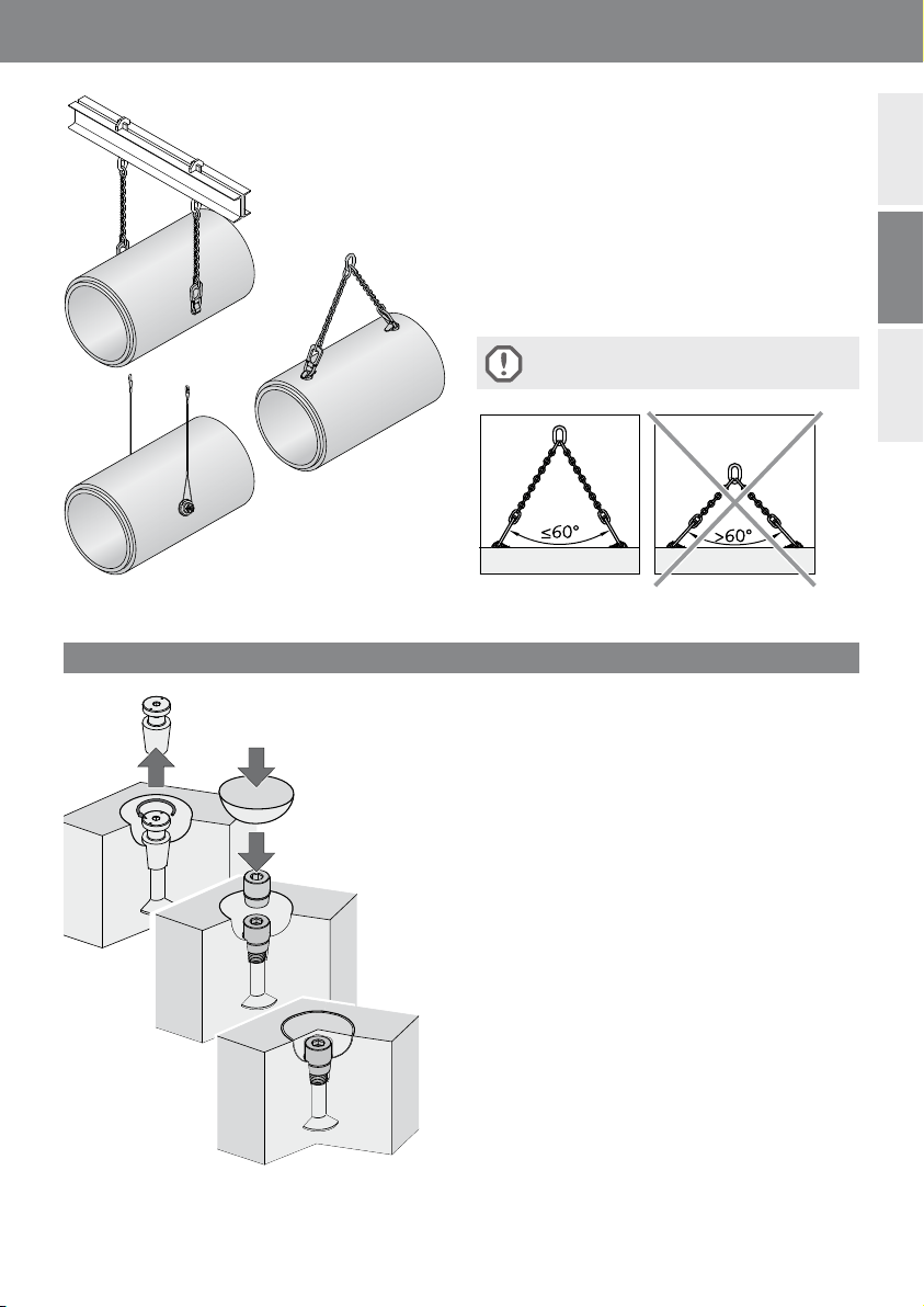
Generell sind die Unfallverhütungsvorschriften zu beachten.
Die Sicherheitsregeln für Transportanker gemäß der VDI-Richtlinie
VDI/BV-BS 6205 sind einzuhalten.
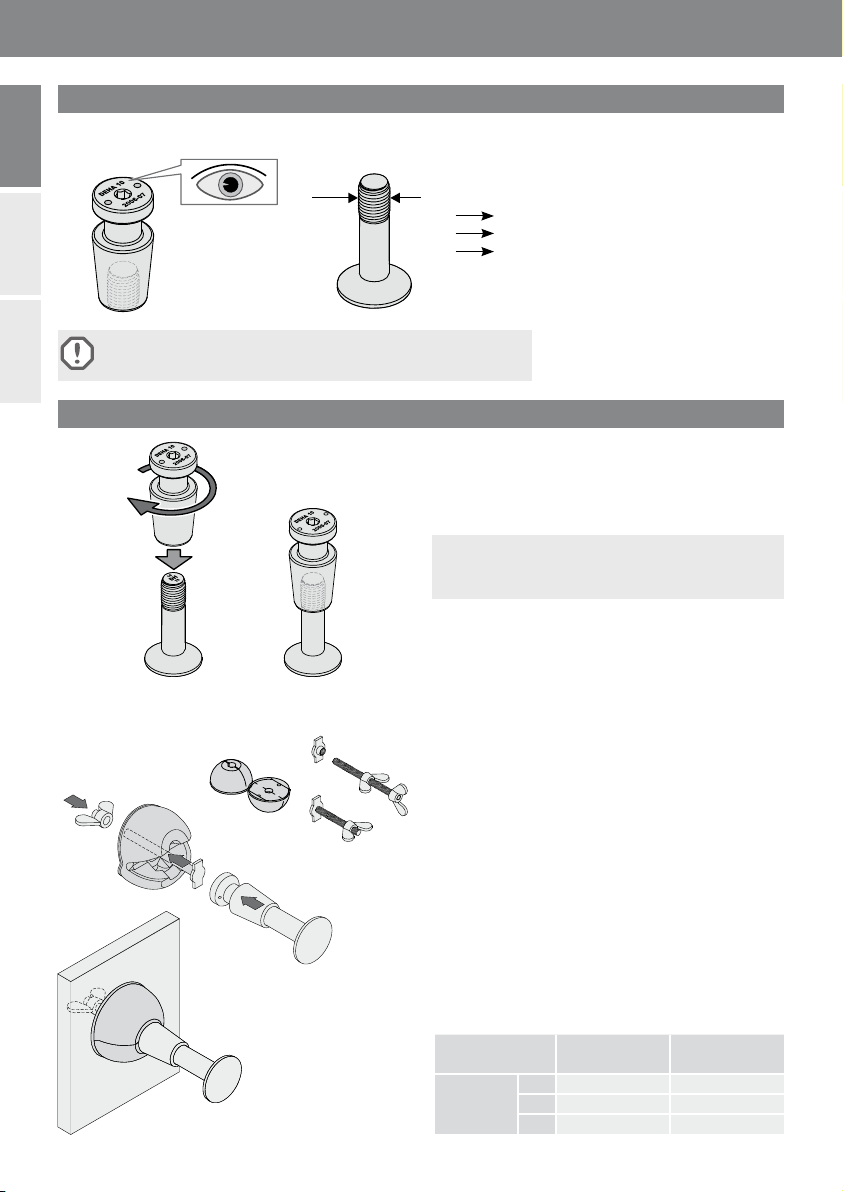
Kennzeichnung
Einbau
10
20
32
10
20
32
M30
M39
M52
Schlüsselweiten Adapter
SW1
Dichtkappe
SW2
Lastklasse 10 10 17
20 17 17
32 19 19
SW1
AnkerschaftAdapterkopf
Montage:
Für den Einsatz als Transportanker müssen beide Teile von
Hand zusammengeschraubt werden, bis das Gewinde nicht
mehr sichtbar ist.
Zum leichteren Eindrehen und Lösen sollte vorher das
Gewinde des Ankerschaftes etwas eingefettet werden und
der Adapterkopf von außen mit Schalöl versehen werden,
um ein Kleben am Beton zu verhindern.
Befestigung an der Schalung:
Aussparungskörper (6173-...) mit Stanzblech mit Gewin-
destab (6141-...) oder Stanzblech mit Innengewinde
(6153-...) vormontieren. Der Anker ist durch geeignete
Maßnahmen an der Bewehrung zu befestigen, damit wäh-
rend des Betoniervorgangs die Lage gesichert ist.
6004 6003
M