Español
6© 2020 HALFEN · INST_HFV 02/16 · www.halfen.com
Deutsch EnglishFrançais
HALFEN HFV Notice d‘utilisation
PolskiČesky
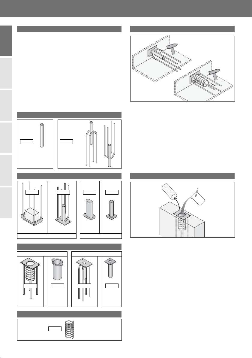
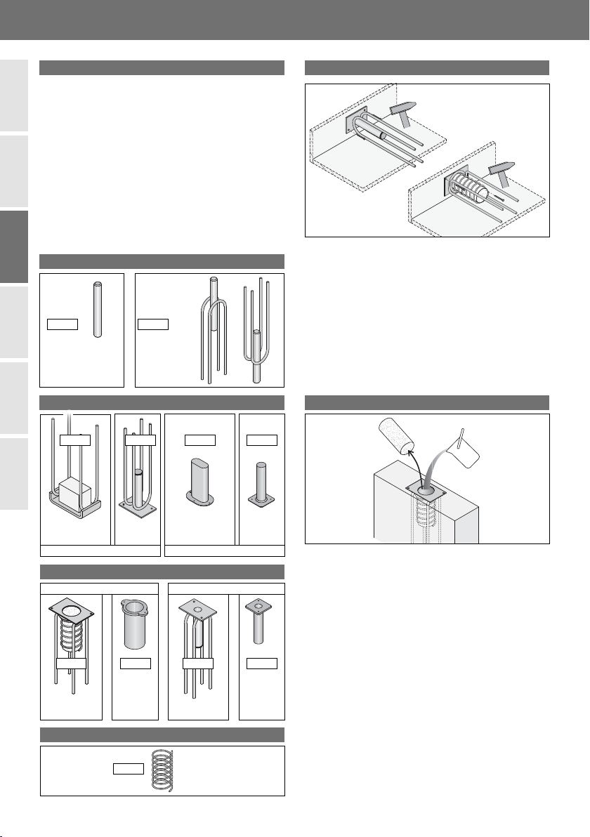
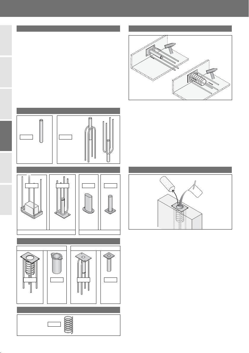
Goupille fixe
avec armature
Goupille libre
HFV 3 HFV 7
1.1 Goupilles en acier inoxydable
Les goupilles de liaison de panneaux sont utilisées pour
transmettre les charges de cisaillement dans des panneaux
préfabriqués et superposés. Chaque liaison est constituée
des composants suivants:
1.1 Goupille en acier inoxydable
1.2 Fourreau à insérer dans la partie du panneau de
façade supérieur
1.3 Fourreau à insérer dans la partie du panneau de
façade inférieur
1.4 Armature de frettage en spirale (recommandé avec
tous les manchons plastique, pour éviter les fissures) Se référer aux plans de coffrage et de renforts d‘armatures,
pour la position exacte des fourreaux de liaison. Avec ces
informations, installer et fixer les fourreaux en les clouant
au coffrage ou avec d‘autres moyen de fixation afin de
sécuriser l‘implantation. Les fourreaux doivent être installés
avec soin, afin qu‘ils ne soient pas désalignés ou insuffi-
samment fixés! Le bord long du fourreau oblong est mis
en place parallèlement à la face finie du béton (en général,
le fond de coffrage).
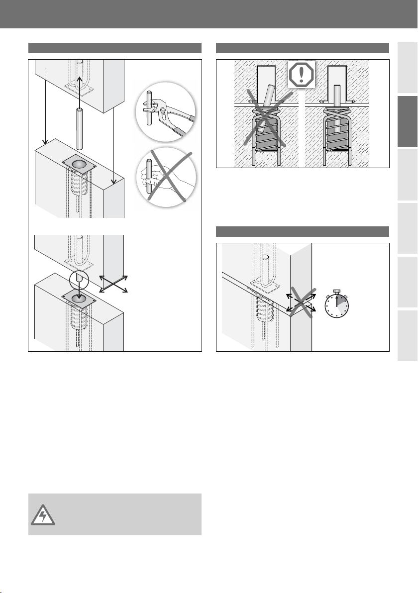
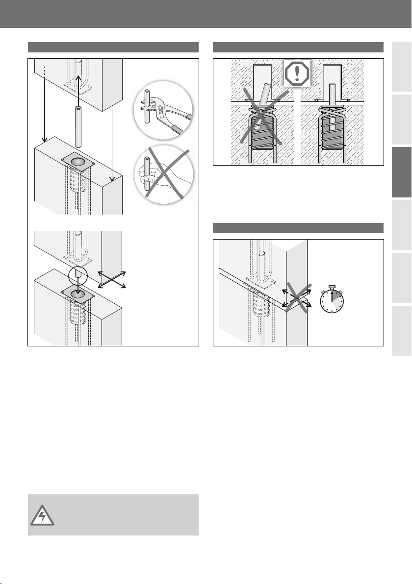
Ne pas utiliser d‘aiguille vibrante au voisinage des
fourreaux!
Il convient de retirer la réservation en styropor lors de
l‘utilisation du fourreau à mortier HFV 4 .
Les fourreaux de scellement HFV 4 ou HFV 9 doivent être
remplis avec du mortier avant l‘assemblage du panneau .
Utiliser un mortier à faible retrait, qui aura au moins la
même résistance de béton que le panneau de façade.
1. Sélectionner les composants 2. Fixation au coffrage
3. Préparations
1.3 Pour le panneau inférieur
1.2 Pour le panneau supérieur
HFV B
1.4 Armature de frettage en spirale
Acier
inoxydable Acier
inoxydable
Acier
inoxydable
Plastique Plastique
HFV 4 HFV 9 HFV 8 HFV 5
Fourreaux de scellement Fourreaux fixes
Fourreau
fixe fretté Fourreau
fixe fretté
HFV 2 HFV 8 HFV 1 HFV 5
Acier inoxydable Plastique
Fourreau à trou
oblong fretté Fourreau à trou
oblong fretté