manuals.online logo
Brands
  1. Home
  2. •
  3. Brands
  4. •
  5. Croydex
  6. •
  7. Indoor Furnishing
  8. •
  9. Croydex WC2800 User manual

Croydex WC2800 User manual

CAB 142 R03
1
AAA B
C
WC2800##
ASHBY 2 DOOR CABINET
ALL PRODUCT DIMENSIONS DETAILED IN THIS
INSTALLATION AND MAINTENANCE MANUAL ARE
APPROXIMATE
ALL ILLUSTRATIONS OF THE PRODUCT ARE FOR
REFERENCE ONLY. COMPONENTS SUPPLIED WITH
INDIVIDUAL PRODUCTS MAY DIFFER
CONTACT DETAILS
Croydex
Central Way
Andover
Hampshire
SP10 5AW
UK
Tel: +44 (0)1264 365881
Email: info@croydex.co.uk
www.croydex.com
PRODUCT DIMENSIONS (SEE ABOVE)
A - 560MM
B - 130MM
C - 580MM
SECTION CONTENTS PAGE
1 INTRODUCTION 2
2 PRE-INSTALLATION 3
3CABINET ASSEMBLY 4 - 6
4MOUNTING THE CABINET 7 - 8
CAB 142 R03
2
x1
MAX
10kg
TABLE OF CONTENTS
SECTION 1
INTRODUCTION
Please follow all assembly and product care instructions to ensure that your product is
assembled safely and retains it's high quality finish.
PLEASE RETAIN THIS MANUAL FOR FUTURE REFERENCE
SAFETY & PRODUCT CARE
1. ALWAYS take care when using power tools, particularly if there is any water in the
working area.
2. ALWAYS wear eye protection when using power tools.
3. ALWAYS check for pipes and cables before drilling into walls.
4. NEVER use a hammer drill when drilling into tiled surfaces.
5. ALWAYS use a drill bit that is suitable for the surface that is being drilled.
6. The wall plugs supplied are for use on solid walls only. For cavity walls or plasterboard
ALWAYS use specialist fixings that are suitable for the type of wall construction.
7. Wall plugs should be inserted flush with wall surfaces. If fitting to a tiled surface, the
wall plugs should be inserted below the surface of the tile to avoid cracking of the tiles.
8. DO NOT slam the door open, as this may damage the hinge.
9. DO NOT use power tools for assembling the product including power drills and
power screwdrivers.
10. DO NOT strike the product with hard or sharp objects.
11. DO NOT use abrasive or chemical cleaners as these may damage the product.
MAX
5kg
Bx2 M3 x 9mm
Countersunk
Screw
Cx2 M4 x 19mm
Pan head
machine Screw
CAB 142 R03
3
FIXING PACK
SECTION 2
PRE-INSTALLATION
Top Bracket Mounting Components
8/11
mm
TOOLS REQUIRED
PRODUCT FITTING
IMPORTANT!
Before attempting to fit or use this product. Ensure that it can be properly installed
in the location you wish it to be in. Refer to the product dimensions found on the
front cover.
Bottom Bracket Mounting Components
Hole Blanking Cap x2Toggle Bolt Wall
Insert x4
Wall Plug &
Mounting Screw x4
Top Hat Bracket &
Cap x2
IMPORTANT!
Push the 11mm
diameter wall
insert into the
11mm hole in the
plaster board for
maximum load
bearing strength.
Ax2 M3 x 13mm
Countersunk
Screw
CABINET ASSEMBLY KIT
IMPORTANT! THE SPACER MOULDING IS NOT REQUIRED WITH THIS CABINET
Cover
Locking Cap
Spacer (Do not use
for this installation)
Mounting Screw
Metal Washer
Top Bracket
(Small Diameter)
O-Ring Spacer (Do not use
for this installation)
O-Ring
Metal Washer
Bottom Bracket
(Large Diameter
with a slot)
Mounting Screw
Locking Cap
Cover
D
x1
Wood Adhesive
fig. 4
CAB 142 R03
4
SECTION 3 - CABINET ASSEMBLY
ATTACHING COMPONENTS
1. Identify the top panel of the cabinet with
this pair of mounting holes for the magnetic
door catch. Using the two screws (A), mount
the magnetic door catch to the top panel.
(See Fig. 1)
fig. 1
2. Insert the 4 door pivot bushings into both
the top and bottom panel of the cabinet as
shown.
(See Fig. 2)
3. Screw in all 8 cam locking pins. 4 into the
bottom panel, 4 into the top panel.
(See Fig. 3)
fig. 3
4. Insert a hinge pin into the hole at the
top and bottom of both doors. Attach the
magnetic door plates with the screws (B).
Then attach the door knobs using the
screws (C).
(See Fig. 4)
fig. 2
A
X2
B
X2
C
X2
TOP PANEL
TOP PANEL
BOTTOM PANEL
CAB 142 R03
5
SECTION 3 - CABINET ASSEMBLY
5. Insert 4 cam locks into the recesses
in each side of the cabinet. Ensure the
pointed arrow is facing the ends of the
panel as shown.
(See Fig. 5)
fig. 5
ASSEMBLING THE CABINET
6. Apply the adhesive (D) to one half of
each dowel, then press firmly into the
each of the two holes in the bottom panel.
Repeat this for the two holes in the top
panel.
(See Fig. 6)
A
d
he
s
iv
e
fig. 6
7. Apply adhesive (D) to the top half of the
dowel on the left hand side of the bottom
panel. Insert the left hand panel down onto
the bottom panel, ensuring that it is flush
with the bottom. Then tighten the locking
cams clockwise to secure in place. DO NOT
OVERTIGHTEN! Wipe away any excess
adhesive. (See Fig. 7)
A
dh
e
sive
fig. 7
8. Insert the back panel ensuring it sits in
the recesses properly.
IMPORTANT: Ensure the back panel is
facing the correct direction. The larger face
should be facing the front of the cabinet.
(See Fig. 8)
fig. 8
9. Repeat step 7 for the right hand panel,
ensure that it slots together with the back
panel.
(See Fig. 7)
IMPORTANT!
FRONT FACE
Pointed Arrow
CAB 142 R03
6
SECTION 3 - CABINET ASSEMBLY
fig. 10
10. Apply adhesive to the top half of both
dowels on the top panel. Locate the top
panel onto the side panels via the dowels
and cam locking pins and press down until
the top panel sits half way down on the
cam locking pins.
(See Fig. 10)
11. Identify the left hand door. To help with
this - take note of the location on the door
of the magnetic door plate. It must contact
the magnetic door catch when the door
swings closed. Then insert the door so that
the hinge pins sit inside the top and bottom
bushings.
Repeat this for the right hand door.
Once both doors are in place. Push the top
panel all the way down until it sits flush.
Wipe away any excess adhesive.
(See Fig. 11a & Fig. 11b)
fig. 11a
12. Tighten all four top locking cams. DO
NOT OVERTIGHTEN! Wipe away any excess
adhesive. (See Fig. 12)
fig. 12
fig. 11b
fig. 14
CAB 142 R03
7
SECTION 4 - MOUNTING THE CABINET
13. Place the cabinet in the desired position
on the wall and mark the position of the
top mounting hole.
(See Fig. 13)
15. Fasten the top bracket to the wall
ensuring the O-ring is correctly seated
at the back of the bracket. DO NOT
OVERTIGHTEN. (This image shows the
solid wall installation.
IMPORTANT: The top bracket has a
smaller diameter outer flange to the
bottom bracket.
(See Fig. 15)
fig. 15
fig. 13
14. Drill an 8mm hole in the marked position.
Then insert the wall plug flush to the surface
of the wall. If fitting to a tiled surface, the wall
plug should be inserted below the surface of
the tile to avoid cracking.
For cavity walls drill an 11mm diameter hole and
assemble the top bracket and metal washer
onto the toggle bolt as shown. Ensure the 11mm
diameter toggle bolt insert is pushed into the
hole in the plaster board wall for maximum
strength.
IMPORTANT!
If the wall plugs are not inserted flush with the
wall surface, the O-ring will not contact the
wall correctly.This will prevent the bracket from
functioning properly.
(See Fig. 14)
16. Hang the cabinet onto the top wall
bracket and secure in place by screwing
the locking cap onto the top bracket. Then,
place the cover onto the locking cap.
(See Fig. 16)
fig. 16
Toggle Bolt Insert
Top Bracket
CAB 142 R03
8
SECTION 4 - MOUNTING THE CABINET
fig. 17
17. Using a spirit level, adjust the cabinet so
that it is level. Once level, accurately mark
a hole in the centre of the bottom fixing
hole using the bottom bracket as a guide.
(See Fig. 17)
21. Assemble the shelf supports and shelf in
the desired position.
(See Fig. 21)
18. Drill an 8mm hole in the marked position.
Then insert the wall plug flush to the surface
of the wall. If fitting to a tiled surface, the wall
plug should be inserted below the surface of
the tile to avoid cracking.
For cavity walls drill an 11mm diameter hole
and assemble the bottom bracket and metal
washer onto the toggle bolt as shown. Ensure
the 11mm diameter toggle bolt insert is pushed
into the hole in the plaster board wall for
maximum strength.
IMPORTANT!
If the wall plugs are not inserted flush with the
wall surface, the O-ring will not contact the
wall correctly. This will prevent the bracket from
functioning properly.
fig. 18
19. Screw the bottom bracket in position as
shown and check that the cabinet is level. If the
cabinet is not level, loosen the screw and adjust
the cabinet until it is level. The slot will allow...
fig. 19a
20. Additional top fixings are supplied if
required and these can be fixed with wall
plugs or toggle bolts.
(See Fig. 20)
fig. 20
fig. 21
fig. 19b
for adjustment. Once level, re-tighten the screw.
Then screw the locking cap to the bottom
bracket and fit the cover.
(See Fig. 19a & 19b)

Other Croydex Indoor Furnishing manuals
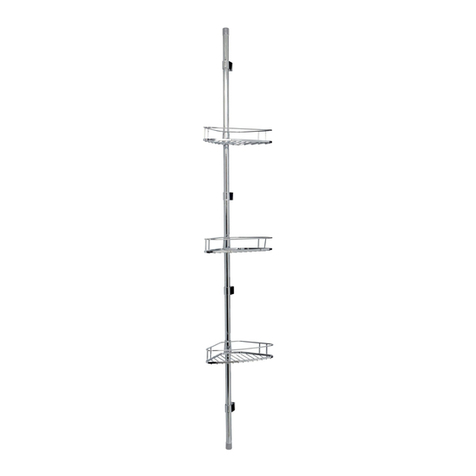
Croydex Triple Corner Basket Set User manual

Croydex

Croydex Triple Corner Basket Set User manual

Croydex AD149641 User manual

Croydex

Croydex AD149641 User manual
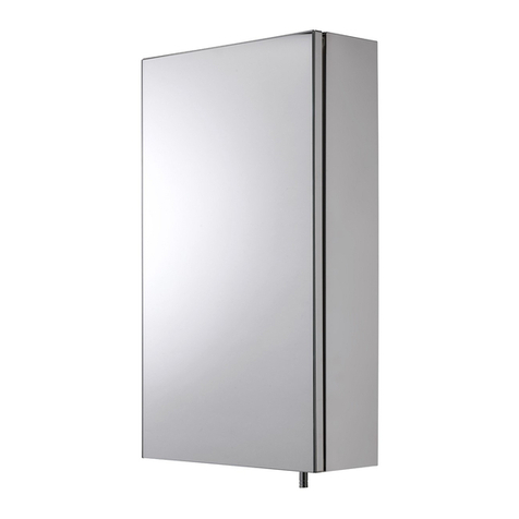
Croydex Anton WC736005 Installation guide
Croydex

Croydex Anton WC736005 Installation guide

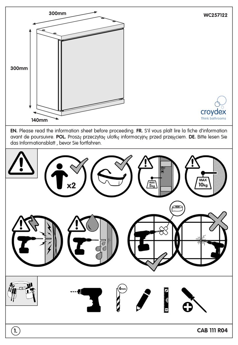
Croydex WC257122 User manual

Croydex

Croydex WC257122 User manual

Croydex MM710100E User manual

Croydex

Croydex MM710100E User manual
Croydex Arun User manual

Croydex

Croydex Arun User manual
Croydex Chetsford User manual

Croydex

Croydex Chetsford User manual
Croydex SIMPLICITY WC257222 User manual
Croydex

Croydex SIMPLICITY WC257222 User manual

Croydex WC257122 User manual

Croydex

Croydex WC257122 User manual
Croydex MM720400E User manual

Croydex

Croydex MM720400E User manual

Croydex Chetsford Series User manual

Croydex

Croydex Chetsford Series User manual

Croydex Boston WS010122 User manual

Croydex

Croydex Boston WS010122 User manual
Croydex WC9400 Series User manual

Croydex

Croydex WC9400 Series User manual
Croydex AP400522 User manual

Croydex

Croydex AP400522 User manual
Croydex AP130422 User manual

Croydex

Croydex AP130422 User manual
Croydex 5012044112446 User manual

Croydex

Croydex 5012044112446 User manual
Croydex MM720200E User manual

Croydex

Croydex MM720200E User manual
Croydex WC101169 User manual

Croydex

Croydex WC101169 User manual
Croydex PA155941 Manual

Croydex

Croydex PA155941 Manual

Croydex WS010522 User manual

Croydex

Croydex WS010522 User manual

Croydex WC410122 User manual

Croydex

Croydex WC410122 User manual

Croydex AD149341 Manual

Croydex

Croydex AD149341 Manual

Croydex Flexi-Fix 1919 User manual

Croydex

Croydex Flexi-Fix 1919 User manual

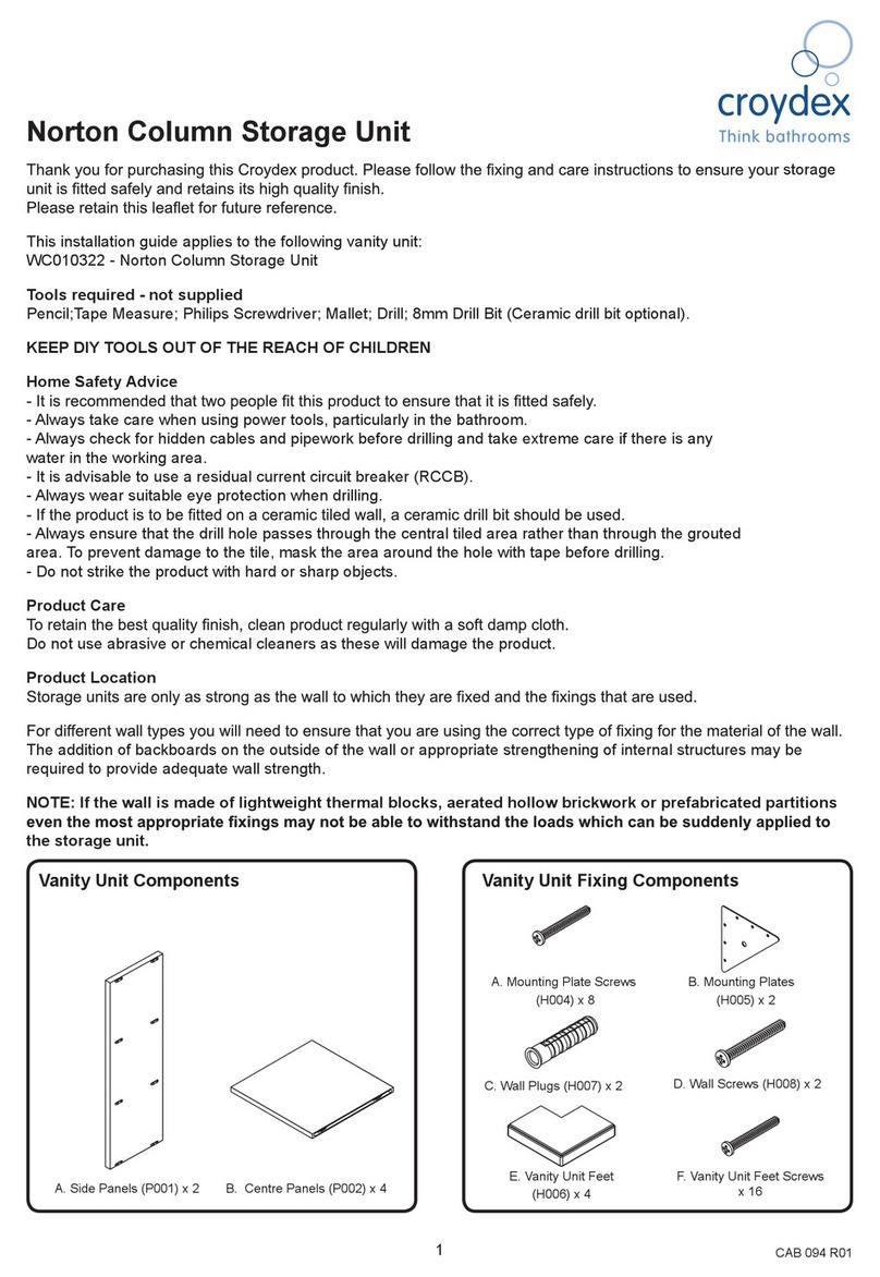
Croydex Norton WC010322 Manual

Croydex

Croydex Norton WC010322 Manual

Popular Indoor Furnishing manuals by other brands
Rapidline LAB CH Assembly instructions

Rapidline

Rapidline LAB CH Assembly instructions

BLACK RED WHITE INDIANA JLOZ 90 Assembly
BLACK RED WHITE

BLACK RED WHITE INDIANA JLOZ 90 Assembly

TRENDMANUFAKTUR TOKYO 02 Assembly instruction

TRENDMANUFAKTUR

TRENDMANUFAKTUR TOKYO 02 Assembly instruction

Draper TopSpin installation instructions

Draper

Draper TopSpin installation instructions

Wonderland 532 manual

Wonderland

Wonderland 532 manual

Furniture Solutions AKIRA 18AKIT08 instruction manual
Furniture Solutions

Furniture Solutions AKIRA 18AKIT08 instruction manual

Safavieh Furniture NST9008A manual

Safavieh Furniture

Safavieh Furniture NST9008A manual
VIGOUR clivia manual

VIGOUR

VIGOUR clivia manual

IKEA BLECKBERGET installation instructions
IKEA

IKEA BLECKBERGET installation instructions

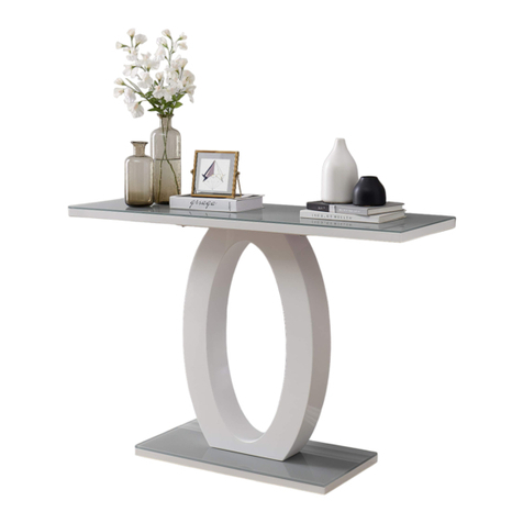
FURNITUREBOX GIOVANI CONSOLE TABLE Assembly guide
FURNITUREBOX

FURNITUREBOX GIOVANI CONSOLE TABLE Assembly guide

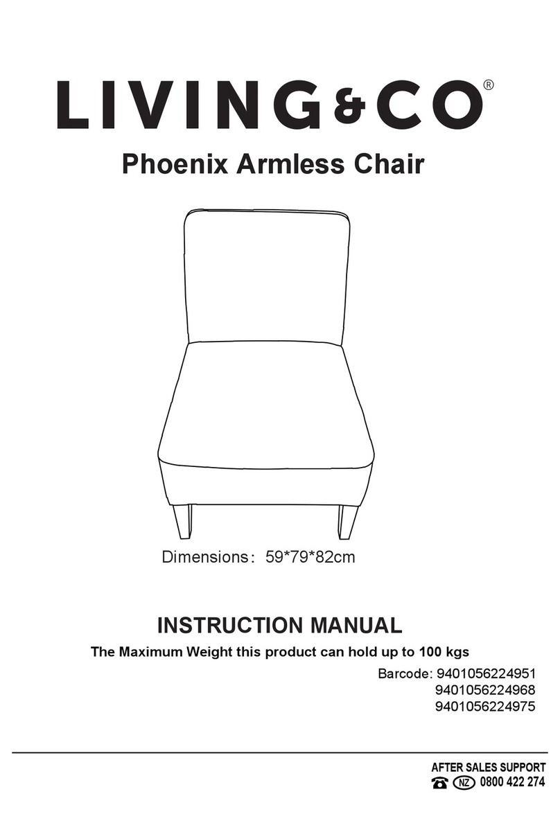
Living & Co Phoenix instruction manual
Living & Co

Living & Co Phoenix instruction manual

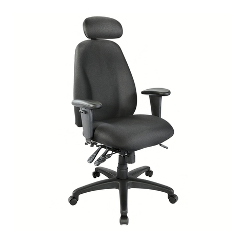
realspace Maverick 11000 PRO Series Assembly instructions and warranty information
realspace

realspace Maverick 11000 PRO Series Assembly instructions and warranty information

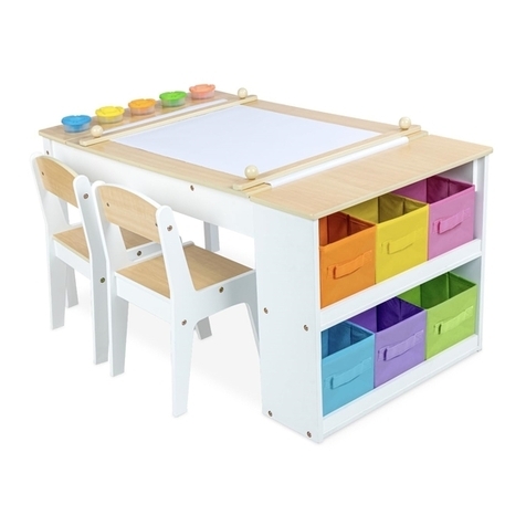
milliard Art Table Assembly instructions
milliard

milliard Art Table Assembly instructions

SAUTHON easy SERENA UT161A Technical manual

SAUTHON easy

SAUTHON easy SERENA UT161A Technical manual

Argos Eastleigh Ant Pewter 09H Assembly instructions

Argos

Argos Eastleigh Ant Pewter 09H Assembly instructions

Mocka Eliza Six Drawer Assembly instructions

Mocka

Mocka Eliza Six Drawer Assembly instructions

Kathy Ireland OFFICE KI60102-03SU Assembly instructions
Kathy Ireland

Kathy Ireland OFFICE KI60102-03SU Assembly instructions

Hailey Home AT0512 Assembly instructions

Hailey Home

Hailey Home AT0512 Assembly instructions

manuals.online logo
manuals.online logoBrands
  • About & Mission
  • Contact us
  • Privacy Policy
  • Terms and Conditions

Copyright 2025 Manuals.Online. All Rights Reserved.