manuals.online logo
Brands
  1. Home
  2. •
  3. Brands
  4. •
  5. CRU Dataport
  6. •
  7. Enclosure
  8. •
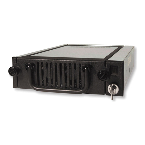
  9. CRU Dataport DE50 SATA User manual

CRU Dataport DE50 SATA User manual

Rugged, Reliable, Mobile, SecureTM
1-800-260-9800 www.CRU-DataPort.com
DE50 SATA Install Guide
Removable SATA 3Gb/s Drive Enclosure
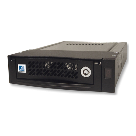
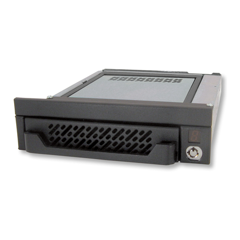
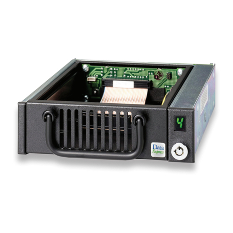
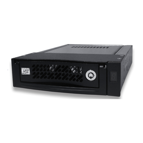
SATA 3Gb/s DE50 receiving frames are indicated by their BLUE LED. PATA
DE50 receiving frames are indicated by their GREEN LED. PATA DE50 carriers
are indicated by a Data Express Logo, while the new SATA 3Gb/s DE50
carriers are indicated by the SATA logo.
NOTE: For SATA 3Gb/s operation, a SATA 3Gb/s controller and
SATA 3Gb/s hard drive are required.
Front Panel
Unit ID Number Indicator
This LED is for ID display purposes only. This BLUE LED displays the
status of the SATA 3Gb/s DE50 device carrier if the carrier is Installed
and Locked in the receiving frame or if the carrier is removed from the
receiving frame. If the carrier is Installed but not Locked in the receiving
frame, a “u” will be displayed to indicate an unlocked condition. The unit
ID number is selected by means of the unit ID select switch inside the
receiving frame using a special alignment tool supplied with the DE50.
Activity Indicator
A small BLUE dot next to the unit ID number illuminates to indicate
when the host computer is accessing the data on the DE50 carrier. This
dot will flash during communication with the host computer.
NOTE: Some drives may support this feature. Refer to your drive
manufacturer’s documentation for further information.
Unit ID Select Switch
This rotating switch selects the unit ID number of the disk drive. The
Unit ID number is for ID display purposes only.
Key Lock/Drive Power Switch
Performs three functions. The key switch assures proper seating of the
drive carrier within the receiving frame, turns power to the drive carrier
ON and OFF, and prevents unauthorized removal or installation of the
carrier. For the computer to access data on the disk drive, the key must
be turned counterclockwise to the locked position.
Eject Button
Push to eject drive carrier from receiving frame.
5.25” Adapter Bracket
Some DE50 models do not include a 5.25” Adapter Bracket.
Receiving Frame Motherboard
I/O Connector
The input/output connector provides a standard interface for all SATA
signals.
SATA Power Connector
15-Pin SATA power connector to accept DC power.
NOTE: If your system does not accommodate the SATA power con-
nector, simply use the SATA-to-DC Power adapter cable (included in
the accessory bag) to connect to your system’s DC power.
Figure 1: Front Panel
Key Lock/
Power Switch
Eject Button
Drive
Carrier
5.25” Adapter
Bracket
Unit ID Select
Switch Location
Unit ID
Number
Indicator
Activity
Indicator*
*Some drives may support the Activity Indicator feature. Refer to your drive
manufacturer’s documentation for further information.
Figure 2: Receiving Frame Motherboard (rear view)
SATA Power
Connector
I/O
Connector
Rugged, Reliable, Mobile, SecureTM
1-800-260-9800 www.CRU-DataPort.com
Drive/Drive Carrier Installation
1. Loosen and remove the four (4) M3 Phillips Flat Hd. screws located on
the sides of the drive carrier unit. Save these screws for Step 5.
2. Since the drive carrier unit is
shipped pre-assembled,
disassemble the drive
carrier unit into its three
main components (Figure 3).
3. Attach the SATA connector
on the Drive Carrier Circuit
Board to the drive (Figure 4).
4. Carefully turn the drive/circuit board assembly upside-down (drive
is bottom-mounted into bracket). Install the mounting bracket/bottom
plate assembly and secure with four (4) M3 screws (provided) as
shown in Figure 5. Make sure that the drive circuit board is properly
seated in the mounting bracket slot before tightening screws.
5. Carefully insert the drive/bracket assembly into the top cover and
secure with four (4) M3 screws (saved from Step 1).
Receiving Frame Installation
NOTES: Some DE50 models do not include a 5.25” adapter bracket.
Some DE50 models include three (3) accessory bags (instead of one).
These additional accessory bags contain:
Four (4) Phillips Shoulder screws (used for mounting the receiving frame
into certain Dell PC systems) and four (4) M3 Phillips Pan Head screws
(used for mounting the receiving frame into standard PC systems).
For 3.5” peripheral slots, use the appropriate screws (either Shoulder or M3
Pan Head) for mounting the receiving frame into your particular PC system.
NOTE: The unit ID number display is for ID display purposes only!
Limited Product Warranty
CRU-DataPort (CRU) warrants the Data Express DE50 to be free of sig-
nificant defects in material and workmanship for a period of three years
from the original date of purchase. CRU’s warranty is nontransferable
and is limited to the original purchaser.
Limitation of Liability
The warranties set forth in this agreement replace all other warranties. CRU ex-
pressly disclaims all other warranties, including but not limited to, the implied
warranties of merchantability and fitness for a particular purpose and non-infringe-
ment of third-party rights with respect to the documentation and hardware. No
CRU dealer, agent or employee is authorized to make any modification, exten-
sion, or addition to this warranty. In no event will CRU or its suppliers be liable
for any costs of procurement of substitute products or services, lost profits, loss
of information or data, computer malfunction, or any other special, indirect, con-
sequential, or incidental damages arising in any way out of the sale of, use of,
or inability to use any CRU product or service, even if CRU has been advised of
the possibility of such damages. In no case shall CRU’s liability exceed the actual
money paid for the products at issue. CRU reserves the right to make modifica-
tions and additions to this product without notice or taking on additional liability.
Certification
EMI Standard: FCC Part 15 Class B, CE
EMC Standard: EN55022, EN55024
FCC Certification
This device has been tested and found to comply with the limits for a Class B
digital device, pursuant to Part 15 of the FCC rules. Operation is subject to the
following two conditions:
1. This device may not cause harmful interference, and
2. This device must accept any interference received; including interfer-
ence that may cause undesired operation.
Register your product at www.CRU-DataPort.com
A7-050-0002 Rev. 2.1
For 5.25” peripheral slots, the 5.25” adapter bracket must be installed.
The receiving frame is side-mounted into the adapter bracket using four
(4) M3 Pan Head screws (provided).
With the drive carrier locked in place inside the receiving frame, install
the DE50 into the 5.25” drive opening in the computer or expansion
chassis. Use the appropriate guides to position the DE50 unit, and fas-
ten it into place with four (4) self-tapping screws (included). Mounting
holes are provided on each side and the bottom of the adapter bracket
to accommodate a variety of mounting configurations. Use the mounting
holes which best suit the computer or expansion chassis configuration.
Unit ID Select Switch Settings
The following table lists the Unit ID Select Switch settings. Refer to
Figure 1 for the location of the ID Select Switch inside the receiving frame.
Top
Cover
Drive Mounting
Bracket/Bottom Plate
Assembly
Drive Carrier
Circuit Board
2.5” SATA Drive
(not included)
Drive Carrier
Circuit Board
Drive w/ Circuit
Board Installed
M3 Phillips Flat Hd.
Screw (4 total)
Circuit
Board
Note: Make sure the circuit board is
properly seated in the bracket slot before
securing drive to the bracket assembly.
Figure 5: Drive Mounting
Bracket Installation
Figure 4: Drive Carrier Circuit Board Installation
Figure 3: Drive Carrier Components
Unit ID Select
Position 0123456789
Unit ID Number
Display Blank 0 1 Blank Blank 2 3 Blank Blank Blank
Other CRU Dataport Enclosure manuals

CRU Dataport RTX Secure 410-SJ User manual

CRU Dataport

CRU Dataport RTX Secure 410-SJ User manual

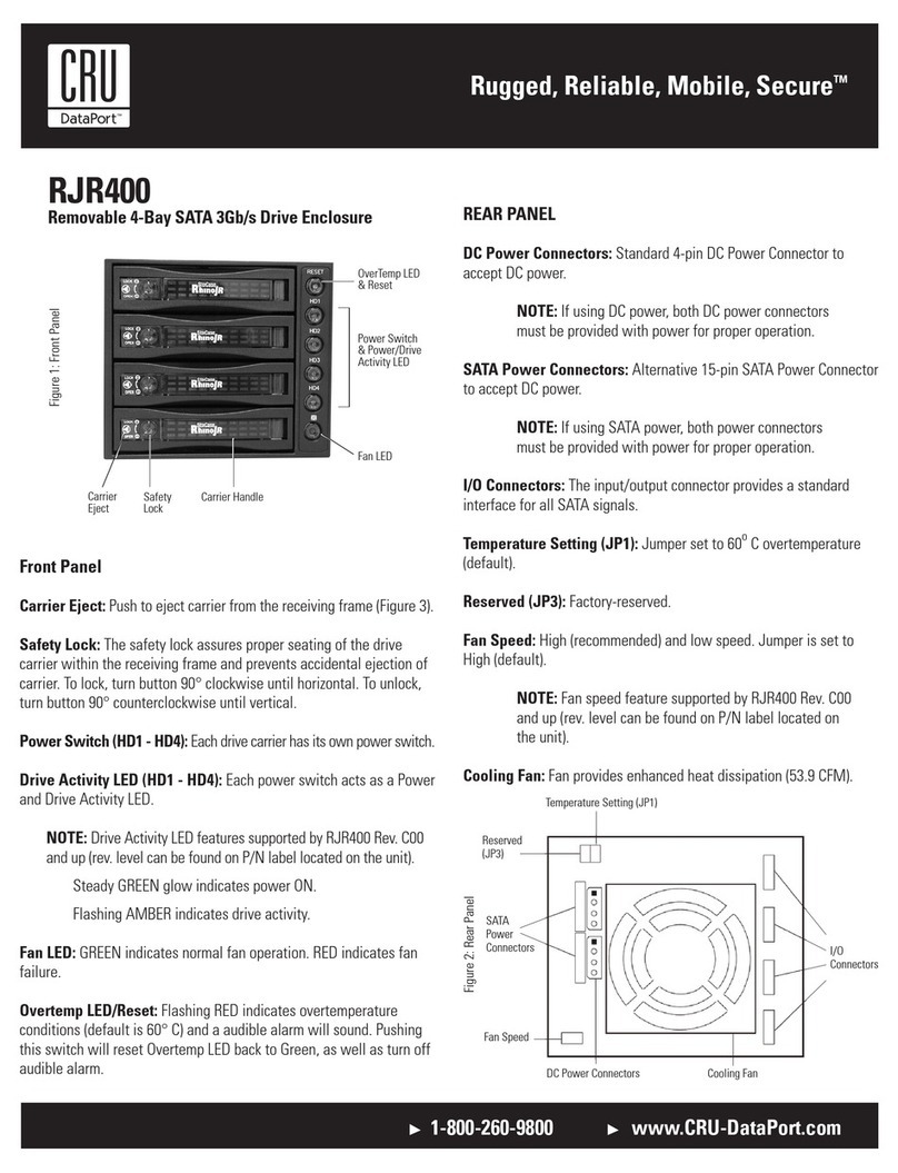
CRU Dataport RJR400 User manual

CRU Dataport

CRU Dataport RJR400 User manual

CRU Dataport RTX 610-IR User manual

CRU Dataport

CRU Dataport RTX 610-IR User manual

CRU Dataport RTX110-3Q User manual

CRU Dataport

CRU Dataport RTX110-3Q User manual

CRU Dataport Multi-Lane DataPAK User manual

CRU Dataport

CRU Dataport Multi-Lane DataPAK User manual

CRU Dataport ToughTech Duo-QR User manual

CRU Dataport

CRU Dataport ToughTech Duo-QR User manual

CRU Dataport Data Express DX115 DC User manual

CRU Dataport

CRU Dataport Data Express DX115 DC User manual

CRU Dataport Data Express DX115 SATA User manual

CRU Dataport

CRU Dataport Data Express DX115 SATA User manual

CRU Dataport DE100 Ultra320 SCA User manual

CRU Dataport

CRU Dataport DE100 Ultra320 SCA User manual

CRU Dataport RJR110 Ultra320 User manual

CRU Dataport

CRU Dataport RJR110 Ultra320 User manual

CRU Dataport DataPort 350 User manual

CRU Dataport

CRU Dataport DataPort 350 User manual

CRU Dataport DE110 Series User manual

CRU Dataport

CRU Dataport DE110 Series User manual

CRU Dataport RTX430-3QR User manual

CRU Dataport

CRU Dataport RTX430-3QR User manual

CRU Dataport Data Express DE75 SAS User manual

CRU Dataport

CRU Dataport Data Express DE75 SAS User manual

CRU Dataport HotDock Secure User manual

CRU Dataport

CRU Dataport HotDock Secure User manual

CRU Dataport TT-Q User manual

CRU Dataport

CRU Dataport TT-Q User manual

CRU Dataport RTX800-XJ User manual

CRU Dataport

CRU Dataport RTX800-XJ User manual

CRU Dataport ToughTech m3 User manual

CRU Dataport

CRU Dataport ToughTech m3 User manual

CRU Dataport Data Express DE200 SCSI User manual

CRU Dataport

CRU Dataport Data Express DE200 SCSI User manual

CRU Dataport DE100 ATA 33 User manual

CRU Dataport

CRU Dataport DE100 ATA 33 User manual

CRU Dataport DE100 Series User manual

CRU Dataport

CRU Dataport DE100 Series User manual

CRU Dataport SecureDock User manual

CRU Dataport

CRU Dataport SecureDock User manual

CRU Dataport DataPort 3 User manual

CRU Dataport

CRU Dataport DataPort 3 User manual

CRU Dataport Data Express DE110 Ultra ATA133 User manual

CRU Dataport

CRU Dataport Data Express DE110 Ultra ATA133 User manual

Popular Enclosure manuals by other brands

HBM VKK1-4 Mounting instructions

HBM

HBM VKK1-4 Mounting instructions

Positron BRX-VDSL2-8 quick start guide

Positron

Positron BRX-VDSL2-8 quick start guide

Rutenbeck PPR 3SC-M installation guide

Rutenbeck

Rutenbeck PPR 3SC-M installation guide

HP A1896A installation guide

HP

HP A1896A installation guide

Thermaltake ARMOR REVO GENE VO800M1W2N user manual

Thermaltake

Thermaltake ARMOR REVO GENE VO800M1W2N user manual

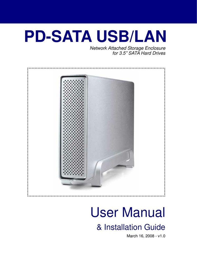
Macpower & Tytech PD-SATA user manual

Macpower & Tytech

Macpower & Tytech PD-SATA user manual

Antec Solution SLK2600AMB User’s user manual

Antec

Antec Solution SLK2600AMB User’s user manual

JMR electronics MARLIN FC-SATA300/SAS user guide

JMR electronics

JMR electronics MARLIN FC-SATA300/SAS user guide

Thermaltake Element T VK9000 Series user manual

Thermaltake

Thermaltake Element T VK9000 Series user manual

Icy Box IB-362StUS2-B Specifications

Icy Box

Icy Box IB-362StUS2-B Specifications

Lantronix OCA-P181610 install guide

Lantronix

Lantronix OCA-P181610 install guide

Rockford Fosgate PUNCH RFT4061 Installation & operation

Rockford Fosgate

Rockford Fosgate PUNCH RFT4061 Installation & operation

CARVIN 412 Series manual

CARVIN

CARVIN 412 Series manual

EMC CLARiiON CX700 Hardware reference

EMC

EMC CLARiiON CX700 Hardware reference

PCB Piezotronics IMI SENSORS 682A00 Installation and operating manual

PCB Piezotronics

PCB Piezotronics IMI SENSORS 682A00 Installation and operating manual

StarTech.com S251BMU313 instruction manual

StarTech.com

StarTech.com S251BMU313 instruction manual

D-Link DNS-343-1TB Specifications
D-Link

D-Link DNS-343-1TB Specifications

Icy Box IB-RD3640SU3E2/SU3 user manual

Icy Box

Icy Box IB-RD3640SU3E2/SU3 user manual

manuals.online logo
manuals.online logoBrands
  • About & Mission
  • Contact us
  • Privacy Policy
  • Terms and Conditions

Copyright 2025 Manuals.Online. All Rights Reserved.