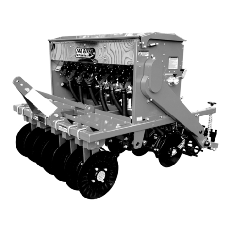
CrustBuster 4000 Series Use and care manual

4000 SERIES
ALL PLANT & MIN-TILL DRILL
OWNER'S MANUAL
(4-01) #604694

Identification
Your CrustBuster® drill is identified by a Serial Number and Model Number. Record these numbers
in the spaces provided in this manual and refer to them when ordering parts or requesting service.
Serial Number Model Number
Warranty
WARRANTY: In addition to the implied warranties of fitness and of merchantability,
CrustBuster®/Speed King, Inc. warrants new products sold by it to be free from defects in
workmanship and material for a period of 12 months, from the date of delivery to the first user
customer. Warranty on purchased parts (cylinder, blades, bearings, shanks, etc.) will be the same
as that offered by the appropriate manufacturer of these parts.
EXCLUSIONS: No warranty of any kind is made by CrustBuster®/Speed King, Inc. with regard
to new products which have been subject to operation in excess of recommended capacities,
misuse, abuse, negligence, or accident, or have been altered or repaired in any manner not
authorized by CrustBuster®/Speed King, Inc. CrustBuster®/Speed King, Inc. is constantly striving
to improve its products. Changes in design and improvement will be made whenever
CrustBuster®/Speed King, Inc. believes the efficiency of its products will be improved thereby, but
without incurring any obligation to incorporate such improvements in any products which have
been shipped or are in service. No obligation exists for compensation of unauthorized repairs or
modifications without prior approval. And in no event will CrustBuster®/Speed King, Inc. be liable
for consequential damages, such as but not limited to: downtime, delayed or late tillage or
planting, etc.
WARRANTY REGISTRATION: This warranty is not valid unless registered with
CrustBuster®/Speed King, Inc. within 10 days from the date of purchase. It is the sole
responsibility of the selling retail dealer to fill out the registration forms and see that they are
properly filed with CrustBuster®/Speed King, Inc.
WARRANTY PROCEDURE: Should any part fail to conform with this warranty,
CrustBuster®/Speed King, Inc. will repair or replace the part or parts which do not conform. If a
part is defective, take it to your authorized CrustBuster® Farm Equipment Dealer immediately,
along with your warranty registration, and complete the proper forms requesting a warranty
adjustment. Our representative will pick up the part to be returned to the factory for examination.
If the customer (first user) requests that a new part be substituted for the old part, a new part will
be charged to the dealer who will in turn charge the customer. If the part is found by us to be
defective, a credit for the part will be given to the dealer to be passed on to the customer. If the
dealer or customer wishes to repair the part, this will be done only if authorized by
CrustBuster®/Speed King, Inc. This warranty procedure is in addition to all remedies authorized
by law.
CRUSTBUSTER®/SPEED KING, INC.
Box 1438
Dodge City, KS 67801
Specifications are subject to change without notice. ® is a registered trademark of CrustBuster/Speed King, Inc.

Table of Contents
Introduction
Identification & Warranty . . . . . . . . . Inside Cover
Safety ................................2-8
OperatingCautions ...................... 9
Field Operating Checklist . . . . . . . . . . . . . . . . . . 9
Lubrication and Operating
Lubrication, Maintenance, and Service . . . . . . 10
Transporting ........................... 11
Folding & Unfolding . . . . . . . . . . . . . . . . . . . . . 11
Leveling .............................. 11
Wobble Slot Seed Cup Adjustments . . . . . . . . 12
Chain Tension on Drive Shaft . . . . . . . . . . . . . 12
Meter Man Acreage Counter . . . . . . . . . . . . . . 13
Sprocket Box Adjustment . . . . . . . . . . . . . . . . . 13
Field Operation
OperatingSpeed ....................... 14
Adjustment Procedures . . . . . . . . . . . . . . . . . . 14
Scraper Adjustments . . . . . . . . . . . . . . . . . . . . 14
Blade Gap Adjustment . . . . . . . . . . . . . . . . . . . 14
All Plant Settings . . . . . . . . . . . . . . . . . . . . . 15-17
Min Till Settings . . . . . . . . . . . . . . . . . . . . . . 18-19
Calibration and Drilling Rates
Calibration ............................ 20
Sprocket Box Operation . . . . . . . . . . . . . . . . . . 20
Sprocket Locations . . . . . . . . . . . . . . . . . . . . . . 21
Seed Rate Charts . . . . . . . . . . . . . . . . . . . . . 22-29
Repair Parts
Hitch ................................. 30
Tongue ............................... 31
Wing Sections
4025 / 4030 ..................... 32-33
4020 ............................44-45
Tool Bars
4025 / 4030 All Plant ................. 34
4020 All Plant ...................... 35
4025 / 4030 Min Till ................. 36
Slide Fold & Pull Bar . . . . . . . . . . . . . . . . . . . . . 37
Grain Box
4025 / 4030 ......................38-39
4020 ............................40-41
Drives
4025 / 4030 ......................42-43
4020 ............................44-45
Gear Boxes
4025 / 4030 ......................46-49
4020 ............................50-57
Repair Parts - Cont.
Opener Assemblies & Blades
All Plant Opener . . . . . . . . . . . . . . . . . . 54-55
All Plant Blades . . . . . . . . . . . . . . . . . . . . . 58
Min Till Opener . . . . . . . . . . . . . . . . . . . 56-57
Min Till Blades . . . . . . . . . . . . . . . . . . . . . 59
Feed Tubes . . . . . . . . . . . . . . . . . . . . . . . . . . . 60
Clutch Lever Assemblies . . . . . . . . . . . . . . . . . 61
Bearing Bracket Assemblies . . . . . . . . . . . . . . 61
Hub Assemblies . . . . . . . . . . . . . . . . . . . . . . . . 62
Clutch Assemblies . . . . . . . . . . . . . . . . . . . . 63-64
Presswheel Assemblies . . . . . . . . . . . . . . . . 64-67
Hydraulic Cylinders . . . . . . . . . . . . . . . . . . . . 68-69
Markers
4025 / 4030 . . . . . . . . . . . . . . . . . . . . . . 70-71
Tri-Fold..........................72-74
4020 .............................. 75
Marker Blade Assembly . . . . . . . . . . . . . . . 76
Marker Cylinder . . . . . . . . . . . . . . . . . . . . . 76
Valve Bracket Assembly . . . . . . . . . . . . . . 77
Hydraulics
4020 -Triple . . . . . . . . . . . . . . 78-79
4025 -Triple . . . . . . . . . . . . . . 80-81
4030 -Triple . . . . . . . . . . . . . . 82-83
4020 -Triple w/Markers . . . . . . 84-85
4025 -Triple w/Markers . . . . . . 86-87
4030 -Triple w/Markers . . . . . . 88-89
4020 / 4025 -Double w/Markers . . . . 90-91
4030 -Double w/Markers . . . . 92-93
Spring Tine Harrow . . . . . . . . . . . . . . . . . . . . . 94
Harrow Layouts
4020 x 7½" . . . . . . . . . . . . . . . . . . . . . . 95
4020 x 8" . . . . . . . . . . . . . . . . . . . . . . 96
4020 x 10" . . . . . . . . . . . . . . . . . . . . . . 97
4025 x 7½" . . . . . . . . . . . . . . . . . . . . . . 98
4025 x 8" . . . . . . . . . . . . . . . . . . . . . . 99
4025 x 10" . . . . . . . . . . . . . . . . . . . . . 100
4030 x 7½" . . . . . . . . . . . . . . . . . . . . . 101
4030 x 8" . . . . . . . . . . . . . . . . . . . . . 102
4030 x 10" . . . . . . . . . . . . . . . . . . . . . 103
Lighting System . . . . . . . . . . . . . . . . . . . . . . . 104
Fertilizer Unit
Settings, Cleaning, & Storage . . . . . . 106-107
Sprocket Locations . . . . . . . . . . . . . . . . . 108
Fertilizer Seed Rate Chart . . . . . . . . . . . . 109
Drive ........................110-111
Bearing Bracket Assemblies . . . . . . . . . . 111
Gear Boxes . . . . . . . . . . . . . . . . . . . . 112-115
Chain Tightening Instructions . . . . 115
Box Assembly . . . . . . . . . . . . . . . . . . 116-117
Box Bottom Assemblies . . . . . . . . . . . 118-119
Drive Clutch Assembly . . . . . . . . . . . . . . . 119
Feed Tubes . . . . . . . . . . . . . . . . . . . . . . . 120
Troubleshooting
.................... 121

2
BE A SAFE OPERATOR
BY THINKING BEFORE ACTING
AND
BY READING
YOUR OWNER'S MANUAL
Avoid Accidents
Most accidents, whether they occur in
industry, on the farm, at home, or on the
highway, are caused by the failure of some
individual to follow simple and fundamental
safety rules or precautions. For this reason
most accidents can be prevented by recog-
nizing the real cause and doing something
about it before the accident occurs.
———————
Regardless of the care used in the design
and construction of any type of equipment,
there are many conditions that cannot be
completely safeguarded against without
interfering with reasonable accessibility and
efficient operation.
A CAREFUL OPERATOR
is the Best Insurance Against an Accident.
The complete observance of one simple
rule would prevent many thousands
of serious injuries each year.
That rule is:
Never Attempt to
Clean, Oil, or Adjust
A Machine While It Is In Motion.
To Our Customers
The following pages and illustrations are
printed to help supply you with the knowledge
to better operate and service your new
CrustBuster equipment.
We are proud to have you as a customer
and feel you will be proud to be a
CrustBuster owner.
Any piece of equipment needs, and must
have, a certain amount of service and main-
tenance to keep it in top running condition.
We have attempted to cover all the adjust-
ments required to fit most conditions; how-
ever, there may be times when special care
must be taken to fit a condition.
Study this owner's manual carefully and
become acquainted with all the adjustments
and operating procedures before attempting
to operate your new equipment. Remember,
it is a machine and has been designed and
tested to do an efficient job in most operating
conditions and will perform in relation to the
services it receives.
If special attention is required for some
condition, ask your CrustBuster dealer; he
will be glad to help and answer any questions
on operations and service of your new ma-
chine.
TAKE TIME FOR SAFETY

3
Safety

4
Safety

5
Safety

6
Safety

7
Safety

8
Safety

9
Before Operating This Equipment
Read and understand this owner's manual.
Secure implement to tractor drawbar with as large a hitch pin as allowed. A
large bolt with locking nut or castle nut is recommended. Do not use a hairpin or
wire to secure hitch pin. Residue may catch and remove these devices.
CAUTION!
During the unfolding sequence, drill becomes tail
heavy. Do Not stand over tongue during or after un-
folding.
Remove tongue cylinder transport lock strap before
attempting to operate.
Field Operating Checklist
G
Tires at recommended air pressure (44 PSI).
G
Lubrication as required.
G
Seed shafts turned manually to check for obstructions and improper chain
alignment on drive sprockets.
G
Correct sprocket selection and slot width for seed type and size.
G
Calibration as required for accuracy.
G
Drill adjusted for level field operation.
G
Down pressure set for soil conditions.
G
Record starting number on acre meter.
G
Lower drill while moving forward to avoid plugging openers.
G
Drill opener rockershaft fully raised before folding.
G
Check seed depth and adjust accordingly.
G
Allow no riders.

10
Lubrication, Maintenance, and Service
Lubrication and Maintenance
Proper maintenance will extend the life of your drill and
give you years of excellent performance. Refer to the
illustrations below for lubrication requirements. Use a
high quality grease in pivot points and bearings. On
greaseable sealed bearings, be careful not to over-
grease and destroy the dirt seal. Pay attention to
recommended intervals. Oil chains with a light chain
lube. A light penetrating oil should be used on seed
cups initially and at the end of each season. Clean
cups with air pressure or vacuum before applying
penetrating oil.
Do Not Attempt To Service
Your Drill While
It Is In Motion!

11
Clutch Maintenance
CAUTION!
At the start of a new drilling season, or anytime the
drill is going to be used, especially if the drill has
been stored out in the weather all winter long, make sure the
clutch drive is not frozen up. Failure to do this will result in
damage to the clutch assembly.
To make sure the clutch is not frozen up, tighten up the clutch
bolts. This should free the disc torque limiter. If not, use a knife
to free the torque limiter from one or the other. Reset clutch
back to where it was. Do Not use any oil or penetrating oil of
any kind.
Transport Instructions
Before Attempting to Operate Tongue
Cylinder,
Remove Transport Lock Strap.
The clevis or mono hitch will stay level on the 4000 Drill, making
it very easy to hook to the tractor. Attach the hoses to the
hydraulic ports on your tractor and operate the tongue up or
down to align with the tractor drawbar. Once the hitch pin or
large bolt is in place, extend the tongue cylinder fully to raise the
front of the drill. Raise the support stand before moving the drill.
Folding and Unfolding Drill
Always Raise Openers Completely
Before Folding Drill!
Fold Procedure Should Be Done On Nearly Level Ground
With The Tractor Transmission In Neutral.
When drill is plumbed with manual hydraulic selector valves,
change valve handle to change hydraulic flow to the fold
cylinders.
To Unfold:
1. Lower front of drill tongue with tongue cylinder fully retracted
and be sure the wing carrier arms will release from the wing
carrier brackets.
2. Hold hydraulic pressure on fold cylinder until wings are in
position.
To Fold:
1. Raise openers completely out of ground to full up position.
2. Lower front of drill tongue to allow wing carrier arms to clear
the wing carrier brackets.
3. Hold hydraulic pressure on fold cylinder until wings are in
position.
4. Extend tongue cylinder fully for maximum road clearance.
Leveling
It is important that your drill be set level front to back during
field operation. Seeding rate and opener travel will be affected
if it is not. The tongue cylinder is equipped with a number scale
for your convenience. When you are sure the drill is level,
remember the number that is relative to the tongue cylinder
position. After transporting to and from the farmstead or field, it
will be easy to return to level. You should re-check the drill
especially if field conditions are different.

12
Wobble Slot Seed Cup Adjustments and Service
The wobble slot seed cups should be checked against
the slot gauge initially and anytime service has been
performed on the seed shaft or individual seed cups.
Refer to the drawing below for proper adjustment if
repairs have been made.
To verify that all seed cups are set the same on the shaft,
start with all cups fully closed. A slight crack between the
cup halves would be considered normal tolerance. If any
individual cup is not "zeroed out," open the slot width
using the adjusting handle, loosen allen set screws and
adjust to equal others on shaft.
To determine if the gauge is reflecting the correct seed
cup slot width, open the seed cups using the adjusting
handle. Notice that wobble slot halves are positioned
differently on the hex shaft. Identify a cup that will accept
a piece of ½" keystock or other measuring device com-
fortably and give solid contact against each half. It may
be necessary to turn the hex shaft slightly to position the
particular seed cup correctly. Close the slot width firmly
against the measuring device. At the cup next to the
wobble slot adjusting handle, position the
gauge to equal the slot width you have just measured
with the keystock by loosening with a screwdriver and
sliding in or out.
Before removing the keystock, make certain the bearing
located on the adjustment lever is securely running
between the shaft bushings. Adjusting bushings must
be set screwed tightly to shaft with zero to 1/64" toler-
ance between the bushing and bearing. Excess toler-
ance in this area will allow the seed shaft to float from
right to left, thus opening and closing wobble slot and
varying the seed rate.
Small changes in rate can be made by opening or
closing slot width. To close the slot width with grain in
the box, close the slot down a maximum of 1/8" and
then rotate the shaft one turn to clear the slot. Repeat
this process until the desired slot width is selected.
Seeding rate is affected by seed size, seed treat-
ments, foreign material, and test weight. Refer to
seed rate charts as guidelines for desired seeding
rates.
Chain Tension on Drive Shaft
When making sprocket changes to the seed shaft, tighten
chain to leave approximately 1/2" of flex. The final sprocket
must allow the hex shaft to slide within the sprocket when the
adjusting lever is moved. If the chain is too tight, bowing and
binding of box end will occur making seed cup
adjustment difficult. Lightly lubricate the shaft
where the sprocket will slide. DO NOT
OVERTIGHTEN CHAIN.

13
Spacing 20' 25' 30'
6" .00307 .00369
7 ½" .00212 .00246 .00294
8" .00191 .00224 .00271
10" .00152 .00177 .00212
Meter Man Acreage Counter
(Option)
Calibration
Use the formulas below to determine your implement
calibration factor or refer to the predetermined factors
listed when using CrustBuster drills.
DT = Distance traveled with one counter shaft rotation
(when using two magnets, divide DT by 2).
WW = Working Width of implement (in inches).
WW x DT/2 = Calibration factor
6272640
NOTE: Whenever a gear change is made on the shaft
being monitored, you will need to enter a new calibration
factor.
Entering Calibration Factor
1. Depress ON/C
2. Round off factor to 5 digits
3. Enter factor (remember decimal point)
4. Depress + key
5. Depress = key
6. Depress decimal point (screen display 0)
CrustBuster Drill
Meter Man Factors by Model
4000 Drills
Sprocket Box Adjustment
The sprocket box design will enable the operator to set
a wobble slot width once for a given seed size and
change rates by changing the speed of the seed shaft.
Choose a range of seeding rates that you wish to
operate in, set the slot width as indicated by the chart
and simply change knob position with the slide handle to
select seed rate.
A narrow slot width will produce more even distribution
and spacing in the row.
For round seeds, the ideal slot width can be determined
by measuring seed size. To attain singular file flow of
seeds from the wobble slot seed cup, the slot width
should be greater than one and one half (1 ½) times the
average seed size, but less than two (2) times the
average size.
Ideal Slot Width = Greater than (>) 1½ times seed size
Less than (<) 2 times seed size
To determine average seed size, lay out 20-30 seeds in
single file, each seed touching each other. A short piece
of angle iron can help align the seeds evenly. Measure
distance from end to end with a ruler. Divide that
measurement by the number of seeds to equal the
average seed size. Multiply average seed size times 1½
to find the minimum width. Multiply average seed size
times 2 to find the maximum width. The slot width
should be ideal when set between these values.
Example: 30 seeds measure 9 inches.
9 " divided by 30 seeds = .30"
.30" times 1.5 = .45" .30 times 2 = .60"
Ideal slot width is greater than .45", less than .60"
Ideal slot width = ½"
Refer to seed chart ½" column as a starting point for
setting final seed rate.
To change position, move throw-out lever toward the
rear to disengage the chain from the lower sprocket.
Pull the spring loaded collar outward with two fingers
and slide side to side to the desired gear position. Pull
throw-out lever forward to re-engage the chain.
Sprocket Box

14
Field Operation
Recommended Operating Speed
Operating speeds of 4-7 mph will provide optimum
results from your Min-Till and All Plant drill. Conven-
tional field conditions can warrant speeds in the
upper end of the range. High levels of "tough"
residue due to morning dew or recent moisture,
rough field conditions, rocky fields, or hard ground
may require lower speeds for adequate performance.
Recommended Adjustment Pro-
cedure
Setting your drill requires adjustments be made in a
particular order to ensure the opener will work
properly. You will find it much easier to set the drill
if adjustments are made in the following order:
1. Level the drill
2. Set toolbar rotation
3. Set down pressure
4. Set seed depth
Scraper Adjustment
Opener blade inside scrapers are spring loaded and
require no adjustment. To replace the scraper
blades, remove the rear lock nut and slide both
blades from the stem. Assemble with new blades
and replace onto stem being careful not to over
tighten lock nut.
NOTE: Do not over tighten lock nut. Be sure
scrapers move freely. Failure to do so will
result in damage to scrapers and proper
operation of scrapers. All Plant
Opener
SPRING LOADED SCRAPER
Blade Gap Adjustment
Offset blade designs form better seed furrows and
penetrate and cut in tougher planting conditions. If
using the ALL PLANT opener, as the blades wear
Blade Gap Adjustment -
(cont'd.)
the gap between blades will increase. Removing each
blade from the opener bracket allows the operator to
take shim washers from behind the bearing and re-
adjust the blade gap for better performance. Shim
washers that are removed must then be placed on
outside of blade to maintain length of bolt. Maintain a
3/16" clearance between blades, measuring at the
pinch point. Inadequate clearance will increase wear on
the inside of the lead blade and mean quicker replace-
ment. The lead blade changes sides on the opener on
each half of the drill. The right blade on ALL PLANT
openers is installed with a right hand threaded bolt.
The left blade is installed with a left hand threaded bolt.
If the MIN-TILL opener is used, the offset design is
achieved by using a 15" leading blade and a 13" trailing
blade. One bolt and lock nut secures both blades in
the proper angle by tightening the bearing races
against the opener bracket. Be sure to hold the bolt as
the nut is removed or replaced. The bolt is bent to the
proper angle for the blades to meet at the front pinch
point. Since it is mounted with one bolt, the MIN-TILL
opener blades require no gap at the pinch point. Shim
washers may be needed to achieve this. When
tightening blades, rotate the bent bolt until bearing
races are flat and flush against beveled surface of
opener blade bracket.
ALL PLANT opener shown
LEAD
BLADE
PINCH
POINT
3/16" GAP

15
TOOL BAR LIFT CYLINDER SET
AT RECOMMENDED SETTING.
CYLINDER RETRACTED WITH
DEPTH SCREW STOP
TURNED OUT 1". THIS
MAKES CYLINDER LENGTH
FROM PIN HOLE TO PIN
HOLE 21¼" AS SHOWN.
NOTE: SET BOTH
CYLINDERS PER TOOL
BAR THE SAME TO
PREVENT TWISTING OF
TOOL BAR.
4025 & 4030
Weight Brackets
4020
Weight Brackets
If you have purchased a Min-Till Drill, the operation procedures continue on page 18.
All Plant Drill
Opener / Tool Bar Adjustments
The All Plant units are attached to a 4x4 bar that is
rotated by two cylinders on each section of the drill.
Each cylinder uses a screw adjustable depth stop on
the cylinder rod. The adjustable depth stop should be
set to rotate the 4x4 bar square to the 7x7 frame in all
conditions.
After the drill is leveled, rotation of the toolbar must be
set. Using the screw adjustable stop on the lift cylin-
der, adjust rotation of the toolbar with the screw adjust-
ment turned out 1" for an initial recommended setting.
Adjustment range of the presswheel depth quadrant
will be affected if the toolbar does not rotate far enough
or goes beyond perpendicular. If the toolbar
is not set correctly, the opener travel
range will not allow for penetration into
low areas or provide clearance when
meeting obstructions.
Check that both tool bar lift cylinders on
each section are set the same. DAMAGE
TO TOOL BAR WILL RESULT IF THEY
ARE NOT SET THE SAME.
Additional Weighting /
Weight Brackets
When operating the All Plant drill in hard ground
conditions, it will be necessary to add weight to the
frame. This can be achieved two different ways.
Optional weight bars are available to place into the 7 x
7 main frame. Simply remove the bolted step caps and
slide as many as six weight bars into the frame. (Refer
to Figure shown at right.)

16
All Plant Drill
Setting Down Pressure
The parallel linkage opener design assures the opera-
tor the opener blades and presswheel operate on the
same level throughout the range of up and down travel.
Due to the location of the down pressure spring, the
pressure applied to the opener remains relatively
constant in the entire range of travel. Changing the
spring position from the first (top) notch to the last
(bottom) notch provides 4 different levels of force.
Each notch represents approximately these amounts
of down pressure: . .
Notch 1 (top) 140# Notch 3 . . . 400#
Notch 2 . . . 275# Notch 4 . . . 525#
It may be necessary to add ballast to the drill in the
third or fourth notch. In order that all the opener
springs are able to achieve the down pressure se-
lected, the total weight of the drill must equal that
amount of pressure times the number of row units on
the drill. The parallel linkage arms should have a "live
working action" during field operation. Setting the drill
for too much down pressure without adequate weight
will reduce the ability of the opener to flex and give
good performance.
To determine the correct amount of down pressure,
begin with the unit set in the lightest setting and the
presswheel adjusted all the way up (or deepest set-
ting). Put the openers in the ground and pull forward
50-100 feet. Stop and check opener penetration. If
the opener is not penetrating to the depth you wish to
plant, rotate toolbar upwards until clear of the ground,
and add one more notch of down pressure. Repeat
the process until the opener will penetrate to at least
the depth you wish to plant.
LIGHT
HEAVY
Down Pressure Spring
Replacement
(Refer to drawing on page 17 in Conventional Field
Conditions section.)
If a down pressure spring breaks, the remaining portion
of the spring is easily removed. With the drill raised,
release the spring top latch and pull outward on the
entire spring top assembly as though changing from
notch to notch. Rotate the spring top assembly ¼" turn
while raising the unit to "parallel" position. Push the
lower portion forward to force the spring pivot pin out of
the welded cradles on either side of the linkage. A tab
prevents accidental loss of the down pressure spring.
Remove the cast plug and install in the new spring.
Replace the spring top assembly, raise the row unit to
"parallel" position and pull the lower portion of the
spring into place.
Setting Seed Depth
Depth settings are achieved by moving the depth
quadrant to affect the presswheel relationship to the
opener. Changes are made by pulling the spring-
loaded pin handle and moving the quadrant up or down
with the hand slot. LOWERING the quadrant will set
seed depth shallow --RAISING the quadrant will set
seed depth deeper. Irregular seed placement can be
caused by excessive field speed, residue hairpinning,
rocky conditions, and cloddy or wet soil conditions.
On the side plates holding the depth quadrant are two
holes for the spring loaded pin. If you move the
quadrant one hole without changing the pin location in
the side plate, you will change depth approximately ½".
Smaller ¼" adjustments can be made by alternately
moving the pin from front to back in the side plate
when moving the quadrant plate.
FRONT HOLE
BACK HOLE

17
All Plant Drill
Setting Seed Depth -
(cont.)
DEEP
SHALLOW
Minimum Tillage Conditions
The most challenging condition is often presented
when a high level of residue is present in a "loose" soil
environment. The opener blades will not cut residue
cleanly and can often have a tendency to push or
"bulldoze" residue ahead of the opener discs.
For minimum tillage operations, the lightest spring (top
notch) is recommended. Firming the ground using a
culti-packer or similar tool can aid in packing the
residue for better cutting and blade penetration with
less hairpinning.
The All Plant drill will work well in minimum tillage
conditions if a "stale seedbed" is created. Soil worked
at an earlier date, and allowed to firm and crust over
can give the opener more resistance, allow for better
cutting action, and create a firmer seed furrow. The
first or second notch will usually provide enough down
pressure to penetrate the soil.
Conventional Field Conditions
For tilled field conditions, the lightest spring setting (top
notch) is recommended. More weight will be trans-
ferred to the carrying wheels of the drill when the
toolbar is rotated. Behind tractor and drill tires it may
be necessary to adjust individual row units for extra
down pressure or different depth setting. Setting the
drill in conventional tillage will
be easier if the tillage trips are
kept shallow (2" - 4").
If the first notch presents too
much down pressure, the down
pressure spring assembly can
be removed. With the spring
assembly removed, the ef-
fective down pressure of the
opener is approximately
60#.
With the openers rotated
clear of the ground, release the
latches on the spring top assem-
blies. With the spring top ears
between the parallel arms, raise
the opener halfway and push
the bottom of the spring
and spring pin forward
out of the cradles.
No-Till Conditions
No-till presents many different conditions. Residue
level and condition, previous tillage strips (ridges, plow
dead furrows), soil type, soil moisture and rocky
conditions all increase the demands on the no-till drill.
Many variables and conditions not removed by tillage
trips require greater attention to settings and speed. In
some circumstances, it may be desirable to drill at a
slight angle to existing rows. This will also randomize
the opener disc wear and extend the maintenance
interval for new blades.
As a general rule, less than ideal conditions will require
slower speeds, to reduce hairpinning, improve opener
penetration and residue cutting, reduce rock damage,
and maintain good furrow formation and seed place-
ment.
It is recommended you set the drill beginning with light
down pressures and work your way up to heavier
settings. If the presswheel presses firmly on the seed
slot and control depth evenly, it is unnecessary to add
more pressure. When increased down pressure does
not improve penetration, or carrying wheels lose
ground contact (and seed drive shaft stops), begin
adding ballast with weight bars.

18
Min-Till Drill
Setting Down Pressure
Opener pressure setting is easy and allows separate
settings for tire compaction areas to different soil
conditions from field to field. Ratchet mechanism
allows you to turn the pressure up or down. The locking
key rolls up or down the notch gauge and locks to your
desired setting from 140# to 250# per opener.
Notch 1 . . 140#
Notch 2 . . . 190#
Notch 3 . . 210#
Notch 4 . . 230#
Notch 5 . . 250#
Down Pressure Spring
Adjustment
Row units that run in wheel tracks can be set with
heavier down pressure to assure solid presswheel
action. The following will help in changing spring
pressure.
1. Rotate the tool bar to raise the opener. Fold up the
walkboard to give good access to the front of the
opener.
2. Using ratchet type wrench, roll locking key up or
down notch gauge to desired setting.
Setting Seed Depth
Understanding the tool bar operation and parallel
linkage design will make setting the drill much easier.
Refer to the drawing on the next page.
Rotating the rockershaft DOWN
sets seed depth more SHALLOW.
Each tool bar is controlled by a hydraulic cylinder within
each wheel arm. An adjustable depth stop sets the
travel of the cylinder which in turn determines how
much the tool bar rotates.
Set depth stop in middle position as a starting point.
To set deeper seed depth, screw the depth stop out
and lengthen the cylinder travel. The opener and
presswheel relationship controls the depth of seed.
When lowering the openers, be sure the tool bar is
in the full down position and the cylinder is re-
tracted against the depth stop. The parallel linkage
must be "set" to achieve the desired down pres-
sure and depth control.
Individual presswheels may be set to correct for wheel
track compaction. Usually, these will only need to be
adjusted once if the same tractor is pulling the drill the
entire season. At the rear of the opener, a cam rotation
bracket holds the single presswheel arm. Turn the cam
toward the "D" or "S" to achieve the desired depth
control.
LOWERING the presswheel
will set seed depth more SHALLOW.
DEEP
SHALLOW
This manual suits for next models
3
Table of contents
Other CrustBuster Farm Equipment manuals
CrustBuster
CrustBuster Speed King User manual

CrustBuster
CrustBuster DrillMaster User manual

CrustBuster
CrustBuster Speed King Drive Over- Pit User manual
CrustBuster
CrustBuster 4740 User manual
CrustBuster
CrustBuster 4750 Drill User manual

CrustBuster
CrustBuster COTTON MODULE BUILDER User manual
CrustBuster
CrustBuster Super 20XL User manual
CrustBuster
CrustBuster Speed King 10" BeltVeyor User manual
CrustBuster
CrustBuster Seed Tender 160 User manual
CrustBuster
CrustBuster 4600 Series User manual

