CrustBuster Speed King 10" BeltVeyor User manual

10" BeltVeyor
OWNER'S MANUAL
19012400 10-98

Table of Contents
Warranty Information . . . Inside Front Cover
Operator Qualifications . . . . . . . . . . . . . . . . 1
Safety ........................... 2-3
Operation, Maintenance, & Belt Training . 4-6
Troubleshooting Guide . . . . . . . . . . . . . . . . 7
Specifications ..................... 8-9
Band Locations . . . . . . . . . . . . . . . . . . 10-29
CableWrap..................... 30-31
BeltWrap .........................31
Repair Parts:
8" Electric Drive . . . . . . . . . . . . . . . 32-33
8" PTO Drive . . . . . . . . . . . . . . . . . 34-35
8" Gas Drive . . . . . . . . . . . . . . . . . . 36-37
8" Gas Drive . . . . . . . . . . . . . . . . 37B-37B
8" Hydraulic Drive . . . . . . . . . . . . . . 38-39
10" Electric Drive . . . . . . . . . . . . . . 40-41
10" Electric Drive-Rotary Stacker . . 41A-B
10" PTO Drive . . . . . . . . . . . . . . . . . 42-43
10" Gas Drive . . . . . . . . . . . . . . . . . 44-45
10" Hydraulic Drive . . . . . . . . . . . . . 46-47
Heavy Duty Electric Drive . . . . . . . . 48-49
Heavy Duty PTO Drive . . . . . . . . . . 50-51
Heavy Duty Gas Drive . . . . . . . . . . 52-53
Heavy Duty Hydraulic Drive . . . . . . 54-55
Tail Assemblies . . . . . . . . . . . . . . . . . . 56
Receiver Pivot . . . . . . . . . . . . . . . . . . . . 56
Head Assemblies . . . . . . . . . . . . . . . . . 57
Hopper Assembly . . . . . . . . . . . . . . . . . 57
Undercarriage . . . . . . . . . . . . . . . . 58-65
Trussing . . . . . . . . . . . . . . . . . . . . . 66-56
Return Idler . . . . . . . . . . . . . . . . . . . . . . 68
Half Band . . . . . . . . . . . . . . . . . . . . . . . 68
Jack Mount . . . . . . . . . . . . . . . . . . . . . . 68
90°Spindle . . . . . . . . . . . . . . . . . . . . . . 68
90°Fixed Axle . . . . . . . . . . . . . . . . . . . 69
90°Swivel Axle . . . . . . . . . . . . . . . . . . . 69
90°Tail Axle . . . . . . . . . . . . . . . . . . . 69-A
Double Tail Caster . . . . . . . . . . . . . . 69-A
Tubes - Mild and Stainless Steel . . . . 69-A
Adjustable Deflector . . . . . . . . . . . . . . . 70
Spouts .........................70
Belt Replacements . . . . . . . . . . . . . . . . 70
Flexible Hopper . . . . . . . . . . . . . . . . . . . 71
Assembly Instructions . . . . . . . . . . . . 72-113
Warranty
CrustBuster/Speed King, Inc. of Dodge City, Kansas, warrants consumer products, so far as
the same is of our own manufacture, against defects in material and workmanship under
normal and reasonable use for a period of one (1) year after date of delivery to the original
purchaser. Our obligation under this warranty is limited, however, to furnishing a replacement
part for a defective part, or at our option to repair the defective parts without charge, either
method F.O.B. our works, provided the consumer gives CrustBuster/Speed King,Inc. written
notice within ten (10) days after said part appears to be defective and affords
CrustBuster/Speed King,Inc. an opportunity to inspect. Unless otherwise expressly agreed
to by CrustBuster/Speed King,Inc., the consumer shall bear the expense of installation.
CrustBuster/Speed King, Inc. will not be liable for consequential damages where the loss is
commercial, including but not limited to loss of profit, delays or expenses.
This warranty sets forth the extent of our liability. The foregoing is in lieu of all other
warranties, expressed or implied, including any warranties that extend beyond the description
of the product.

1
Operator Qualifications
Operation of this BeltVeyor shall be limited to competent and experienced persons. In addition, anyone
who will operate or work around BeltVeyor must use good common sense. In order to be qualified, he
or she must also know and meet all other requirements, such as:
1. Some regulations specify that no one under the age of 16 may operate power
machinery. It is your responsibility to know what these regulations are in your
area or situation.
2. Current OSHA regulations state in part: "At the time of initial assignment and at
least annually thereafter the employer shall instruct EVERY employee in the
safe operation of servicing of all equipment with which the employer is, or will
be involved."
3. Unqualified persons are to STAY OUT of the work area.
4. A person who has not read and understood all operating and safety instructions
is not qualified to operate the machinery.
FAILURE TO READ THIS BELTVEYOR MANUAL AND ITS
SAFETY INSTRUCTIONS IS A MISUSE OF THE EQUIPMENT.
Sign Off Sheet
As a requirement of OSHA, it is necessary for the employer to train the employee in the safe operation
and safety procedures with this BeltVeyor. We include this sign off sheet for your convenience and
personal record keeping.
DATE EMPLOYER EMPLOYER'S SIGNATURE

2
BE ALERT!
Your Safety is involved.
General Safety Statement
WATCH FOR THIS SYMBOL. IT POINTS OUT IMPORTANT
SAFETY PRECAUTIONS. IT MEANS "ATTENTION
)
))
)))
))))
))
BECOME
ALERT!"
YOUR SAFETY IS INVOLVED.
It is your responsibility as an owner, operator, or supervisor to know and instruct everyone
using this BeltVeyor at the time of initial assignment and at least annually thereafter, of the
proper operation, precautions, and work hazards which exist in the operation of this BeltVeyor
in accordance with OSHA Regulations.
Safety Is No Accident
The following safety instructions, combined with common sense, will save your equipment
from needless damage and the operator from unnecessary exposure to personal hazard. Pay
special attention to the caution notes in the text. Review this manual at least once each year
with new and/or experienced operators.
1. Read and understand the operator's manual before operating this BeltVeyor.
Failure to do so is considered a misuse of the equipment.
2. Make sure BeltVeyor is secure before operating.
3. Always keep children away from BeltVeyor when operating.
4. The motor controls and reset button must be located so that the operator has
a full view of the entire operation.
5. During regular operation of the BeltVeyor, one person should be in a position
to monitor the operation. A second person should always be nearby to
shutdown the BeltVeyor in case of an emergency.
6. Make sure everyone that is not directly involved with the operation is out of
the work area before beginning the operation.
7. Keep the work area clear of grease, oil, water, and other objects that could
cause a slip or a fall.

3
8. Make sure all safety devices, shields, and guards are in place and are
functional before beginning the operation.
9. Shut off power to adjust, service, or clean the BeltVeyor.
10. Keep hands, feet, and clothing away from moving parts. It is a good idea to
remove all jewelry before starting the operation.
11. Visually inspect the BeltVeyor periodically during operation for signs of
excessive vibration, loose fasteners, and unusual noises.
Electric Safety
1. Electric motors and controls should be wired by a qualified electrician and
meet all standards set by Federal, State, and Local Electrical Codes.
2. Make certain electric motors are grounded.
3. A magnetic starter should be used to protect your motor.
4. Your motor must have a manual reset button.
5. Electrical power must be disconnected before resetting your motor.
6. A main power disconnect switch, with the ability to be locked in the off
position, should be provided. The switch should be locked in the off position
whenever work is to be done on the BeltVeyor or the BeltVeyor is going to
be left unattended.
7. Disconnect power before resetting motor overload.
CAUTION
1. Read and understand instruction manual before operating.
2. Keep all safety shields and devices in place.
3. Make certain everyone is clear before operating machine.
4. Keep hands, feet, and clothing away from moving parts.
5. Shut off power to adjust, service, or clean.
6. Make sure machine is secured before operating.
7. Disconnect power before resetting motor overload.
8. Make certain electric motors are grounded.

4
Pre-Operation Check List
1. Check all bearings for proper lubrication.
2. Check the tube for foreign material.
3. Check all belts for proper tension.
4. Start unit and check conveyor belt alignment while unit is empty.
BELT CARE ………
It is suggested that the unit be run every two to three days or more often if possible. This tends to
keep the conveyor belt alive and stops any forming of the belt to the curvature of the tube while the
unit is not in use.
NOTE: Belt may deteriorate if not in use and exposed to weather conditions for any prolonged
period of time.
Operation Sequence
1. Check wheels to prevent movement during operation.
2. Check all drive belts for proper tension.
3. Make sure conveyor belt is properly tensioned.
4. Allow unit to run empty for a few minutes to flex conveyor belt.
5. Check conveyor belt for proper alignment.
6. Charge conveyor unit as evenly as possible. DO NOT bury intake end in material.
7. Before shutting power off, be certain unit is empty.
PTO DRIVE OPERATION ………
While operating, keep PTO shaft as straight as possible. Prolonged operation with the PTO
shaft at an angle in excess of 15 degrees will reduce U-joint life. DO NOT extend PTO shaft
beyond 80" end to end.
OPERATION WITH ACCESSORIES ………
If the BeltVeyor is used with a self-powered undercar conveyor, start the BeltVeyor first and
the undercar conveyor second. Reverse this procedure for shutdown.
TOWING ………
The BeltVeyor tubular conveyor is designed for maximum portability. Observe the following
towing instructions for both safety and care of the unit.
1. Lower the unit to the extreme down position with slight tension on the cable.
2. Deflate tires to approximately 22 pounds.
3. Make certain the hitch is secure.
4. Be sure to follow normal towing safety precautions.
STORAGE ………
Temporary Storage
1. Relieve tension from all belts; both v-belts and conveyor belt.
2. Store all belt equipment in a dry place. If equipment cannot be stored out of the weather,
cover electrical and mechanical parts with waterproof material.
Prolonged Storage
1. Remove all belts and store in a cool, dark, dry place.
2. Wash conveyor belt thoroughly.
3. Wash conveyor tube both inside and out.
4. Lubricate all bearings.
5. Lower unit to the extreme down position with slight tension on the winch cable.
6. Store all equipment in a dry shelter.

5
Maintenance
Preventive maintenance is the key to the long life of any mechanical device.
Careful and systematic inspection of all BeltVeyor equipment will result in maximum, trouble-free
service.
BELT REPLACEMENT ………
To replace the belt, cut it into and hand rotate the drive pulley until belt has been removed. Install
appropriate belt as outlined in assembly instructions.
DRIVE ASSEMBLY TAKE-UP ………
After extended use, the conveyor belt may stretch to the point that there is not sufficient take-up
in the drive assembly to tighten it. Obtain additional take-up by cutting a 6" to 8" section from the
belt. A new splice lacing may be ordered from your CrustBuster/Speed King distributor or from the
factory.
PERIODIC CLEAN-OUT ………
Due to the characteristics of certain materials, residue sometimes collects between the conveyor
belt and the tube. Check the unit periodically for any material build up in this area. If residue
appears excessive, remove the conveyor belt and thoroughly wash the belt and tube. Allow belt
and tube to dry before reinstalling the belt.
When conveyor is not being used, secure belt to the tube to prevent belt from flopping in the wind,
possibly breaking return idlers or ripping belt.
LUBRICATION ………
All bearing which are fitted with grease zerks should be lubricated at the conclusion of each
operating day. Before greasing the bearings, make certain the zerks are free of dirt, otherwise this
will be passed into the bearing race. If the unit will be out of service for a period of time, purge the
bearings.
Electric motor should be oiled in accordance with the manufacturers recommendations.
Roller chains should be oiled with a light weight oil at the conclusion of each days' operation.
Keep PTO shaft and tube well greased so they move freely.
CONVEYOR BELT TRAINING PROCEDURE ………
A conveyor belt correctly installed and trained will run straight and true. The belt must run centered
on all terminal pulleys, take-up pulleys, and return idlers throughout the entire belt length.
Incorrect installation and training can result in severe edge damage, material spillage, material
leakage through the skirt rubber at the loading point, and excessive power demands. Material
spillage is the usual reason for belt carcass ruptures and pulley cover gouging and stripping, while
leakage at the skirt rubber results in excessive conveyor cover wear under the skirts.
ALIGNMENT ………
All rotating parts -head pulleys, tail pulleys, take-up pulleys, and return idlers- must be at a 90
degree angle to the direction of belt travel, must be level, and the midpoint of each centered on a
line when properly aligned.
Alignment is checked by running a tight wire from the center of the head pulley to the center of the
tail pulley.
Center all other rotating parts on the wire.
Level all rotating parts. If a part is not level, the belt will run to the lower side.
Check that all parts are at a 90°or right angle to the wire. If a part is not at 90°to the center line,
the belt will run to the side that if first contacts.
BELT SPLICING ………
A conveyor belt must not run out at the splice area. Runout will occur if the splice is not in
alignment or correctly made.

6
Operation
1. Prior to the start-up, check to see that belt is free from any objects that would bind or tear.
2. On starting for the first time, with no load on belt, apply power for a few seconds only to see
that the conveyor belt travels in the proper direction, and is well centered in the tube and on
the return.
3. It should be noted at this time that too much tension on the conveyor belt will make adjustment
or training much more difficult, shorten the life of the belt, and waste power. The belt should
be tensioned tight enough so the drive pulley does not slip.
BELT TRAINING ………
It is essential that the conveyor belt be properly trained at all times. For this reason, all rotating
parts should always be at right angles to the conveyor belt to avoid run-off at the tail pulley.
Slight adjustment of pulley shafts may be required to keep belts centered on them i.e., if the belt
runs to one side of the pulley - apply more tension to this side of the belt by advancing the pulley
shaft on this side.
If the belt tends to veer to one side of the return strand, the belt can be centered by "knocking"
ahead (in the direction of belt travel) the end of the return idler to which the belt runs. A belt
correctly installed will usually train well both empty and loaded, except as noted:
1. One or more rotating parts not in alignment.
2. Belt tensions in some part of system (usually at tail section) are below minimum
recommended.
3. Belt not loaded centrally.
When a belt is initially started, it should be jogged around the system to determine if a major runout
occurs which could damage belt and belt edges. If runout occurs at some point of the system, the
reason is usually a return idler or pulley out of alignment before the runout. Alignment should be
rechecked before restarting.
After the belt can be safely run without damage, final training should begin with the tail pulley. The
belt must enter the tail pulley and loading section in the center without movement from side to side.
If the belt is not centered on the tail pulley, the return strand of belt should be observed for any
section which is not centered on the return idlers. If the belt is not centered at some point, move
return idlers starting before this point to correct centering of belt. Movement of idler bracket should
be gradual and only 1/16" to 1/8" remembering that the belt will move in the direction that it first
contacts the idler. The same corrective action should be taken at the head pulley.
After the belt is trained empty, the belt should be trained with a load. The take-up adjustments are
made to prevent belt slip and keep tensions at all points above minimums recommended when belt
is operating with a load.
If slip occurs under load, additional belt tension should be adjusting the take-up only enough to
prevent slip from occurring under load, and when started with a load.
NOTE: Take-up movement must always be at 90°or at a right angle to the direction of belt
travel, or the belt will move out of alignment.
Check periodically to see that no material has built up on pulley faces (between pulley
and belt), idlers, chutes, or in grooves or v-belt sheaves. Remove all rust or foreign
material on take-up screws.
Maintain proper clearance and adjustment on items such as rubber sealing strips.

7
Troubleshooting
If the BeltVeyor equipment malfunctions, the source of faulty operation may frequently be found by
observing the nature of the fault and applying some simple checks and remedies to correct the
malfunction. The following troubleshooting table is provided for this purpose.
BELTVEYOR TROUBLESHOOTING GUIDE
TROUBLE POSSIBLE CAUSES REMEDY
1. Conveyor belt not
running at
operational RPM.
<
<
<
<
<
<
<
<
Engine or motor not developing
operational RPM.
Loose v-belts.
Foreign matter on conveyor belts or
pulleys.
Conveyor belt not tensioned properly.
Lagging worn off of drive pulleys.
Material build up around intake end of
tube.
Is belt upside down?
Frozen bearings.
Correct power source problem.
Adjust v-belt tension.
Clean belt and/or pulleys.
Tighten conveyor belt.
Replace lagging or pulleys.
Clean area under intake.
Make certain smooth side of belt is
running against tube. If not, turn belt
over.
Replace or lubricate bearings.
2. Normal capacity
cannot be obtained.
<
<
<
<
<
<
<
<
<
Engine or motor not developing
operational RPM.
Loose v-belts.
Foreign matter on conveyor belts or
pulleys.
Conveyor belt not tensioned properly.
Lagging worn off of drive pulleys.
Material build up around intake end of
tube.
Is belt upside down?
Frozen bearings.
Conveyor belt not tight.
Correct power source problem.
Adjust v-belt tension.
Clean belt and/or pulleys.
Tighten conveyor belt.
Replace lagging or pulleys.
Clean area under intake.
Make certain smooth side of belt is
running against tube. If not, turn belt
over.
Replace or lubricate bearings.
Tighten conveyor belt.
3. Belt alignment on
bottom pulley.
<
<
<
Pulleys, idlers, or drive assembly
improperly aligned.
Possible build up on belts or pulleys.
Drive assembly improperly aligned.
Adjust pulley and idler alignment. Drive
assembly should be level with head
and tail frame.
Clean belt and/or pulleys.
Align and level drive assembly with
head and tail frame.
4. Excessive wear of
lagging or pulleys.
<
<Conveyor belt not properly tensioned.
Take-up idlers excessively uneven.
Tighten conveyor belt.
Adjust take-up idlers evenly.
5. Pulley drags or does
not turn.
<Frozen bearings. Lubricate or replace bearings.
6. Material build up in
tube.
<Loose belt or worn out material guides. Tension belt and clean tube. If material
guides are excessively worn, replace.

8
10" BVTC SPECIFICATIONS
A B C
RAISED LOWERED RAISED
30°ANGLE
RAISED 30°
ANGLE
20'
9'- 0" 6'- 0" 7'- 5" 18'- 1"
25'
11'- 7" 7'-11" 9'- 9" 22'- 5"
30'
14'- 6" 6'-11" 12'- 7" 26'- 9"
35'
16'- 8" 9'- 2" 15'- 2" 31'- 2"
40'
18'- 4" 10'-11" 18'- 1" 35'-10"
45'
20'- 7" 10'-11" 20'-11" 39' -9"
50'
23'- 4" 12'- 3" 21'- 5" 44'- 1"
55'
25'-10" 12'-11" 23'- 5" 48'- 5"
60'
27'- 4" 13'- 0" 27'- 9" 54'- 9"
65'
29'-10" 11'- 9" 29'- 3" 59'- 3"
70'
34'- 1" 11'- 7" 30'- 1" 61'-10"
75'
36'-10" 13'-10" 33'- 7" 67'- 5"
80'
38'- 1" 13'- 4" 34'- 0" 71'-10"
85'
40'- 6" 14'- 0" 38'- 5" 76'- 3"
G
ALL DIMENSIONS APPROXIMATE.
G
MAXIMUM RECOMMENDED ANGLE 30°.

9
10" BVTC HORSEPOWER
Electric Unit Hydraulic Unit
with Belt
Undercar
without
Belt
Undercar
*See note below
20' 7½ 5
8" Drive
Requirements:
15 gallons per minute
at 1650 psi.
25' 7½ 5
30' 10 7½
35' 10 7½
40' 10 7½
45' 15 10
10" Drive
Requirements:
20 gallons per minute
at 2000 psi
50' 10
55' 15
60' 15
65' 15
70' 20
75' 20
80' 20
85' 20
* In order to operate a hydraulic drive BeltVeyor and a hydraulic Slip-Pit or
Field Loader conveyor off of the same tractor, the tractor will need to have a
Closed Center Hydraulic System
with
Individual Flow Control
for each valve
and a flow rate of
32 gallons per minute at 2000 psi.
** Capacity: Up to 60 tons per hour
of 60 pound per cubic feet material
at 30°incline.
** Variable depending on type and condition of material being handled
and degree of elevation.
10
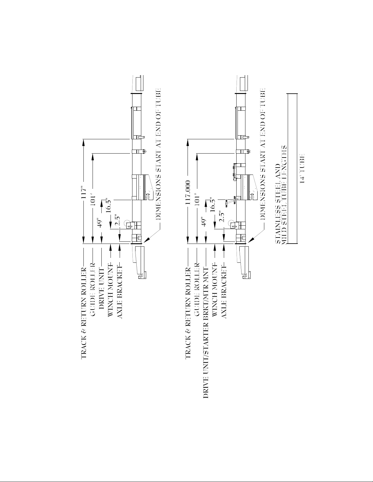
20' Electric20' PTO/Gas/Hyd
10" BVTC Band Locations
20' PTO/Gas/Hyd/Electric

11
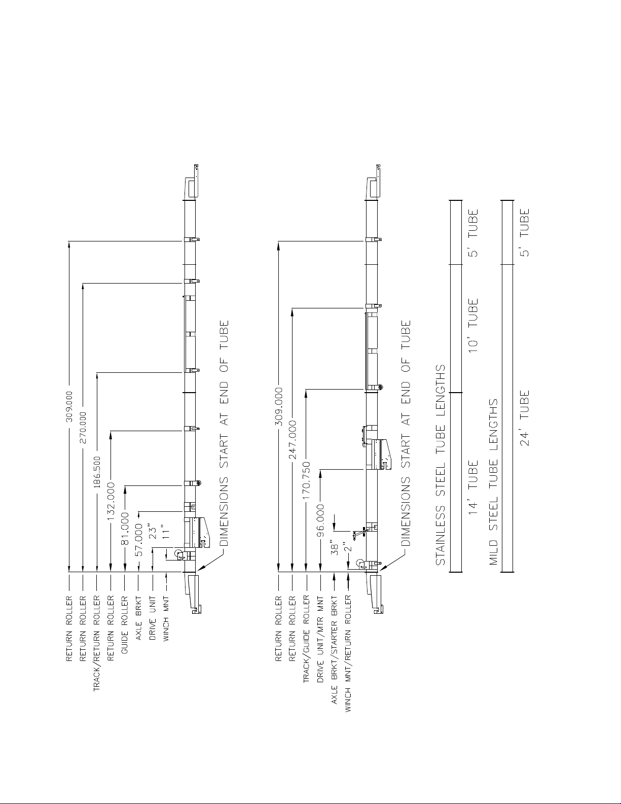
25' PTO/Gas/Hyd 25' Electric
10" BVTC Band Locations
25' PTO/Gas/Hyd/Electric

12
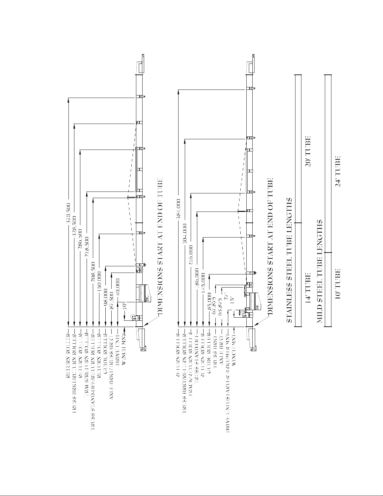
30' Electric30' PTO/Gas/Hyd
10" BVTC Band Locations
30' PTO/Gas/Hyd/Electric
13
35' Electric
Slip-Pit™ Accelerator Not
Available with 35' Electric
35' PTO/Gas/Hyd
Slip-Pit™ Accelerator Not
Available with 35' PTO
10" BVTC Band Locations
35' PTO/Gas/Hyd/Electric
14
40' Electric
Slip-Pit™ Accelerator Not
Available with 40' Electric
40' PTO/Gas/Hyd
10" BVTC Band Locations
40' PTO/Gas/Hyd/Electric
15
45' Electric45' PTO/Gas/Hyd
10" BVTC Band Locations
45' PTO/Gas/Hyd/Electric

16
50' PTO/Gas/Hyd 50' Electric
10" BVTC Band Locations
50' PTO/Gas/Hyd/Electric

17
55' Electric
55' PTO/Gas/Hyd
10" BVTC Band Locations
55' PTO/Gas/Hyd/Electric

18
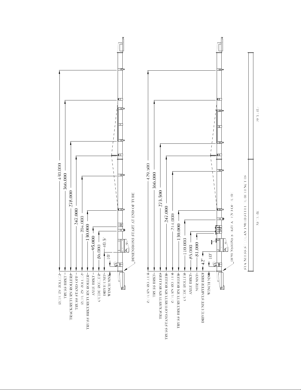
10" BVTC Band Locations
60' PTO/Gas/Hyd
1- Winch Mount
2- Drive Unit
3- Guide Roller
4- Return Roller
5- Axle Bracket
6- Truss Bracket
/ Return Roller
7- Return Roller
8- Truss Stand-off
9- Track / Return Rollers
10- Truss Stand-off
11- Return Roller
12- Truss Bracket
/ Return Roller
13- Return roller
Other CrustBuster Farm Equipment manuals

CrustBuster
CrustBuster Speed King Seed Tote 4 Box User manual

CrustBuster
CrustBuster Super 20XL User manual

CrustBuster
CrustBuster Speed King Drive Over- Pit User manual

CrustBuster
CrustBuster Seed Tender 160 User manual

CrustBuster
CrustBuster 4740 User manual

CrustBuster
CrustBuster 3200 User manual

CrustBuster
CrustBuster SPEED KING 5000 User manual

CrustBuster
CrustBuster 4750 Drill User manual

CrustBuster
CrustBuster DrillMaster User manual

CrustBuster
CrustBuster 4600 Series User manual


