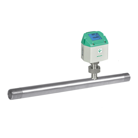
CS Instruments FA 400 User manual

V4-02-2011
INSTRUCTION MANUAL
FA 400
FA 400
Humidity measuring instruments with display and alarm for
measurement of the pressure dew point and the atmospheric
dew point in different applications:
- compressed air plants (refrigeration/adsorption driers)
- granulate driers
- medical gases
- non-corrosive gases, e. g. nitrogen

2 V4-02-2011
FUNCTIONS
Page
Introduction 2
Safety instructions 3
Description 3
Technical data 4
Diagram of instrument / Dimensions of instrument 5
Display operation 6-8
Calibration / Adjustment 9
Warranty 9
Ordering data 10
Notes 11
Contact 12
INTRODUCTION
Dear customer,
Thousands of customers buy our high standard products every year. There are a few good
reasons for doing so:
• The cost-performance ratio - reliable quality at a fair price.
• We have the ideal solutions for your measuring tasks based on our expert
experience gained over 20 years.
• Our high quality standard.
• Of course, our instruments carry the CE symbol required by the EU.
• We issue calibration certificates and hold seminars.
Our service guarantees fast help.
Measuring instrument conforms with DIN EN 61326-1 and 61010-1

3 V4-02-2011
Please read carefully before starting the device!
Attention: Do not exceed a pressure range of > 50 bar with standard version. With spe-
cial versions up to 350 bar.
Observe measuring ranges of the sensor! The probes will be damages if they are
overheated. Observe max. storage and transport temperature as well as max. operating
temperature (e. g. protect measuring instrument from direct sunlight).
The manufacturer cannot be held liable for any damage which occurs as a result of non-
observance or non-compliance with these instructions. Should the device be tampered
with in any matter other than a procedure which is described and specified in the manu-
al, the warranty is cancelled and the manufacturer is exempt from liability.
The device is destined exclusively for the described application.
CS Instruments GmbH offers no guarantee for the suitability for any other purpose and
is not liable for errors which may have slipped into this operation manual. CS Instru-
ments GmbH is also not liable for consequential damage resulting from the delivery, ca-
pability or use of this device.
We offer you to take back the instruments of the instruments family FA 400 which you
would like to dispose of.
Adjustments and calibrations should only be carried out by qualified employees from the
measurement and control technology branch.
Important: Before installation briefly bleed the compressed air in order to remove con-
densate and particles. This prevents soiling of FA 400. Standing air leads to long mea-
suring times.
SAFETY INSTRUCTIONS
!
BESCHREIBUNG
The FA 400 (from -80 bis 20 °Ctd) is the ideal dew point meter with integrated display and
alarm relay for refrigeration, membrane and adsorption driers.
Special features:
- -80 to 20 °Ctd
- Integrated display
- Alarm adjustable via keyboar (60 V, 0.5 A)
- Pressure-tight up to 350 bar (special version)
- Extremely long-term stable langzeitstabil
- Fast response time
- 4...20 mA analogue output
- 2 versions, for refrigeration and for adsortpion driers
Programming via SFA Software.
- Analogue output 4…20 mA scalable, switching for alarm relay adjustable
- Calibration and ajustment including certificate
- Switching between °Ctd, % RH, g/m³ and so on
- Read out of service data

4 V4-02-2011
TECHNICAL DATA
Measuring range -80…50 °C pressure dew point resp. dew point in °Ctd
0…100 % RH
-30…70 °C
Type 0699.0401, FA 400 -20…50 °Ctd ≙4…20 mA
Type 0699.0402, FA 400 -80…20 °Ctd ≙4…20 mA
Type 0699.0403, FA 400 -60…30 °Ctd ≙4…20 mA
Accuracy: typical ±2 °Ctd from -80…-40 °Ctd
±1,5 °Ctd from -40…0 °Ctd
±1 °Ctd from 0…20 °Ctd
Pressure range: -1…50 bar standard, high pressure version up to 350 bar
Power supply: 24 VDC smoothed (16...30 VDC/60 mA)
Output: 4…20 mA 3-Draht-Technik
Protection class: IP 65
EMV: DIN EN 61326
Operating temperature: 0…50 °C
Storage temperature: -40…80 °C
Burden for analogue output: < 500 Ohm
Screw-in thread: G 1/2" stainless steel
Material housing: Zinc alloy, PC, ABS
Sensor protection: Sintered filter 50 μm stainless steel
Connection: M12, 5-pole
Response time t95: < 30 seconds (dry)
< 10 seconds (humid)
Display: 4-digit LCD
Alarm relay: max. 60 V, 0.5 A, NO relay opens in case of alarm and power
failure, alarm value adjustable via keyboard, please see
page 9
Genauigkeit FA410
0,0
0,5
1,0
1,5
2,0
2,5
3,0
-80-60-40-20 0 20
Taupunkt [°C]
Genauigkeit [°C]
Accuracy FA 400
Accuracy (°C)
Dew point (°C)

5 V4-02-2011
INSTALLATION DESCRIPTION
Connector plug A (signal
and supply)
Connector plug B (alarm)
M12 Connector plug A/B
Pin 1 Pin 2 Pin 3 Pin 4 Pin 5
FA 400
Connector plug A SDI -VB +VB +I
4...20 mA NC
Connection cable A
0554.0104 (5 m)
0554.0105 (10 m) brown white blue black grey
Connector plug B NC NC NC REL REL
Connection cable B
0554.0106 (5 m)
0554.0107 (10 m) NC NC NC black grey
SDI Digital Signal (internal data transfer)
-VB Negative supply voltage 0 V
+VB Positive supply voltage 16...30 VDC smoothed
+I Positive 4...20 mA signal
NC Not connected
REL Relay output
Connector plug
Connector plug A :
Connector plug B :
FA 400: Relay NO (60 V, 0.5 A)
Relay opens in case of alarm
and power failure
If no connection cable ( 0553 0104, 0553
0105 ) is ordered the sensor will be sup-
plied with a M12 connector plug. the user
can connect the supply and signal cables
as indicated in the connection diagram.

6 V4-02-2011
INSTALLATION
Please note : CS Instruments recommends the indirect installation with measuring
chamber
Advantage : Easy mounting and dismounting of the probe without interruption of the line.
Quick response time due to quick coupling.
Optimum sensor protection.
Indirectly in the compressed air system
Connect probe with measuring chamber to the com-
pessed air pipe by means of a quick coupling. In case
of compressed air containing oil and dirt particles a pre
-filter should be installed in front of the measuring
chamber. Compressed air flows continuously (at 7 bar
approx. 1 l/min expanded) in the capillary pipe of the
measuring chamber. The reaction times for the humid-
ity reading are shorter than in case of a direct mount-
ing.
Directly in the compressed air system
Screw in probe with G 1/2" thread pressure-tight in the
center or at the top of the compressed air pipe. Take
care that measurement is effected close to the com-
pressed air flow. U-bend pipes or non-flowing com-
pressed air result in very slow reaction times for the
moisture reading.
Measurable gases:
In general, humidity can be measured in all non-corrosive gases. In case of measurements in-
corrosive gases please consult CS Instruments GmbH.

7 V4-02-2011
DISPLAYFUNCTION
SPEZIAL INDICATIONS
FA 400 is configured to be connected to DS 300. In this mode, alarm function in FA 400
is disabled and will be handled by DS 300
Indicates that an alarm is reached. The relay will be switched and the measurement
value is blinking
Display
FA 400 can display up to 3 measured values. This are temperature, rel. humidity and dew point.
For better reading only one measured value is displayed. The measured values are toggled dur-
ing normal operation mode every 3 seconds.
The following changes an be made:
- Alarm value
- Display of measured value (temperature, rel. humidity and dew point)
- Display contrast
- Display upside down
Settings ex work:
- Dew point in °Ctd
Menu buttons
On the top of FA 400 are the capacitive key buttons to operate the display menu.

8 V4-02-2011
DISPLAYFUNCTION
Connection FA 400
After power on, the display will go through an initialisation procedure and will finally show the ac-
tual online value (ex work dew point). Via the configuration menu up to 3 measuring values can
be configured for online display. FA 400 will toggle between the measuring values every three
seconds.
Display current set alarm value
A short click on the “Enter”-button shows the current set alarm value.
Changing of the alarm value see next page.
Slave mode
Changing the settings is only possible with DS 300
Master mode
Changing the settings with pusbuttons FA 400

9 V4-02-2011
DISPLAYFUNCTION
Alarm setting
In order to change the alarm value and the configuration, keep the „Enter“ button pressed for 3
seconds. After input of the unlock code the menu begins with alarm setting. The first digit will start
blinking and can be changed with the „Up“ key. Every digit has to be confirmed with the „Enter“
button.
Menu
You can exit the configuration process by pressing and keeping the “Enter” key for 3 sec or no
key event for 20sec. The configuration before this picture will be save and effected late.

10 V4-02-2011
WARRANTY
If you have reason for complaint we will of course repair any faults free of charge if it can be
proven that they are manufacturing faults. The fault should be reported immediately after it
has been found and within the warranty time guaranteed by us. Excluded from this warranty
is damage caused by improper use and non adherence to the instruction manual.
The warranty is also cancelled once the instrument has been opened - as far as this has not
been mentioned in the instruction manual for maintenance purposes - or if the serial number
in the instrument has been changed, damaged or removed.
The warranty time for the FA 400 is 12 months. If no other definitions are given the
accessory parts have a warranty time of 6 months. Warranty services do not extend the
warranty time.
If in addition to the warranty service necessary repairs, adjustments or similar are carried
out the warranty services are free of charge but there is a charge for other services such as
transport and packaging costs. Other claims, especially those for damage occurring outside
the instrument, are not included unless responsibility is legally binding.
After sales service after the warranty time has elapsed
We are of course there for you even after the warranty time has elapsed. In case of mal-
functions please send us the instrument with a short-form description of the fault. Please do
not forget to indicate your telephone number so that we can call you in case of any
questions.
CALIBRATION/ADJUSTMENT
According to DIN ISO certification of the measuring instruments we recommend to calibrate
and if applicable to adjust the instruments regularly from the manufacturer. The calibration
intervals should comply with your internal specificaton. According to DIN ISO we recom-
mend a calibration interval of one year for the instrument FA 400.

11 V4-02-2011
ORDERING DATA
Order no. Description
0699.0401 FA 400 dew point sensor for refrigeration driers, -20...50 °Ctd
0699.0402 FA 400 dew point sensor for adsorption driers, -80...20 °Ctd
0699.0403 FA 400 dew point sensor, -60...30 °Ctd
0533 0112 Cable FA 200 to FA 400
0553.0104 Connection cable, length 5 m
0553.0105 Connection cable, length 10 m
0553.0106 Alarm cable, length 5 m
0553.0107 Alarm cable, length 10 m
0699.3390 Standard measuring chamber for compressed air up to 16 bar
0699.3590 High pressure measuring chamber up to 350 bar *
0699.3690 Measuring chamber for atmospheric dew point
0699.3790 Measuring chamber for respiratory air bottles up to 350 bar
0699.4004 Special scaling, output in ppm, V/V, % RH, mg/m³
0699.3495 Mains unit in wall housing 230 VAC/24 VDC with alarm processing
0554.0002 Control and calibration set 11.3 % RH
0554.0004 Control and calibration set 33 % RH
0554.0005 Control and calibration set 75.3 % RH
0554.2005 CS Service Software for VA/FA 400 sensors incl. PC connection set, USB
connection and interface adapter to the sensor as well as
CS Soft Professional incl. USB-cable A-A
3200.0003 Precision calibration at 0 °Ctd and 10 °Ctd incl. ISO certificate
0699.3396 Precision calibration at -40 °Ctd incl. ISO certificate
0699.4003 * Special version FA 400 for 350 bar

12 V4-02-2011
DECLARATION OF CONFORMITY

13 V4-02-2011
NOTES

14 V4-02-2011
NOTES

15 V4-02-2011
NOTES

16 V4-02-2011
CONTACT
Sales Office SOUTH
Zindelsteiner Str. 15
D-78052 Villingen-Schwenningen
Phone +49 (0) 7705 97 89 9-0
Fax +49 (0) 7705 97 89 9-20
info@cs-instruments.com
www.cs-instruments.com
Sales office NORTH
Am Oxer 28c
D-24955 Harrislee
Phone +49 (0) 461 700 20 25
Fax +49 (0) 461 700 20 26
info@cs-instruments.com
www.cs-instruments.com
This manual suits for next models
3
Table of contents
Other CS Instruments Measuring Instrument manuals

CS Instruments
CS Instruments DP 500 Instruction manual

CS Instruments
CS Instruments FA 410 User manual

CS Instruments
CS Instruments DP 400 mobil User manual

CS Instruments
CS Instruments DS 300-P User manual

CS Instruments
CS Instruments VA 520 User manual

CS Instruments
CS Instruments FA 300-2 Ex User manual

CS Instruments
CS Instruments VA 550 Ex User manual

CS Instruments
CS Instruments LD 510 User manual

CS Instruments
CS Instruments DS400 User manual

CS Instruments
CS Instruments 0554 0504 User manual