manuals.online logo
Brands
  1. Home
  2. •
  3. Brands
  4. •
  5. CTC Union
  6. •
  7. Switch
  8. •
  9. CTC Union GSW-1005MS User manual

CTC Union GSW-1005MS User manual

Telnet & Web Basic Operation
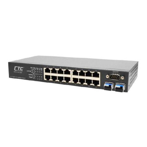
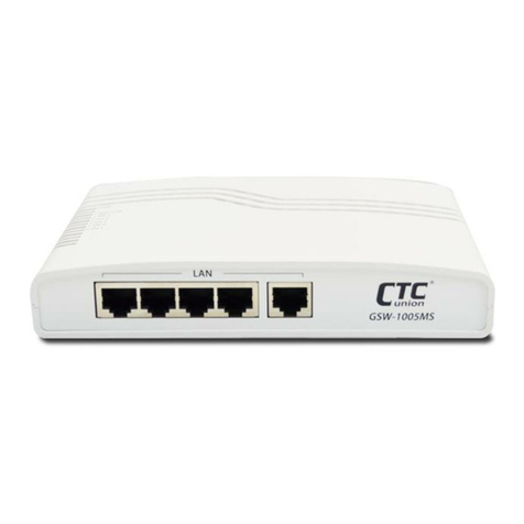
GSW-1005MS & GSW-2008MS are Managed Gigabit Ethernet
CPE switches which provide a number of configuration /
management methods. The first method of configuration /
management uses a command line interface (CLI) via Telnet/SSH
access. This requires that networking be configured so that the
device can be accessed via a LAN port.
For engineers that are not comfortable using CLI, this device
can also be managed using any standard Web Browser in a more
user friendly 'point-and-click' method. Therefore, in most
configuration scenarios, Telnet/SSH will only be used by
experienced networking engineers.
Default TCP/IP settings of GSW-1005MS/GSW-2008MS:
IP Address: 192.168.0.1
Subnet Mask: 255.255.255.0
Username: admin
Password: None (Leave this field blank)
NOTE: For more detailed introduction to management functions
via CLI or Web browser, please refer to Manual PDF file.
.
Introduction
GSW-1005MS & GSW-2008MS are Managed Gigabit Ethernet
CPE switches designed to make conversion between 5-Port or 8-
Port 10/100/1000Base-T RJ-45 and 1-Port or 2-Port
100/1000Base-X fiber optics with SFP optical modules.
Traditionally, transmission distance of Gigabit Ethernet over fiber
interface can be extended from 550m to 100km using the
flexibility of any third party pluggable SFP modules. GSW-1005MS
& GSW-2008MS have an optional cable tray which allows the
installer to enclose the excessive fiber loop within the tray
housing, providing protection for the sensitive fiber at subscriber
site. GSW-1005MS & GSW-2008MS are fully compliant with IEEE
802.3, 802.3u, 802.3ab and 802.3z standards. End-users can
simply connect their devices, such as Ethernet home gateway,
wireless access point or NIC on PC/laptop via 10/100/1000Base-T
twisted pair to the RJ-45 ports of the CPE switch. No Ethernet
crossover cables are required and link status can be easily
monitored from the comprehensive LED display.
Specifications
Ethernet Interface
Connector: 5-Port RJ-45 (GSW-1005MS)
8-Port RJ-45 (GSW-2008MS)
Speed: 10/100/1000Base-T(X)
Transmission Method: Store and Forward Switching
Packet Buffer: 4M bits
Jumble Frame: 9600 bytes
Optical Interface
Connector: 1 SFP Slot (GSW-1005MS)
2 SFP Slots (GSW-2008MS)
Speed: 100/1000Base-X
SFP slots support DDMI
Power
12VDC, 1A
Mechanical
Dimensions: 170 mm (D) x 120 mm (W) x 35 mm (H)
Wall mounting (Optional), Cable Tray (Optional)
Environmental
Operating Temperature: 0°C ~50°C
Humidity: 5%~90% (Non-condensing)
Certifications
FCC, CE, RoHS compliant
Quick Installation Guide
GSW-1005MS
5-Port 10/100/1000Base-T to 1-Port 100/1000Base-X Managed
GbE Switch with (Optional) Cable Tray
GSW-2008MS
8-Port 10/100/1000Base-T to 2-Port 100/1000Base-X Managed
GbE Switch with (Optional) Cable Tray
Panels
Figure 1. GSW-1005MS Front Panel
Figure 2. GSW-2008MS Front Panel
Figure 3. GSW-1005MS Rear Panel
Figure 4. GSW-2008MS Rear Panel
V1.0
- 2 -
- 1 -
www.ctcu.com
1
1
2
3
4
2
4
3
[email protected]
- 7 -
T+886-2-26591021
F+886-2-26590237
E[email protected]
CTC Union Technologies Co., Ltd.
Far Eastern Vienna Technology Center
(Neihu Technology Park)
8F, No. 60, Zhouzi St., Neihu District, Taipei
114
Taiwan
© 2015 CTC Union Technologies Co., Ltd.
All trademarks are the property of their respective owners.
Technical information in this document is subject to change without notice.
Figure 5. GSW-1005MS Top Panel Figure 6. GSW-2008MS Top Panel
Panel Index Reference
No.
Description
1
RJ-45 LAN interface
2
SFP Fiber interface
3
Reset push button
4
Power input port
5
LED indicators
LED Indicators
LED
Color
Meaning
PWR
Blue
Power on.
Off
No power.
Fiber Link
Amber
Fiber link is up and operates at
1000Mbps.
Green
Fiber link is up and operates at
100Mbps.
Amber/Green Blinking
Receive and transmit traffic.
Off
The fiber port link is down.
LAN1~LAN5
(GSW-1005MS)
LAN1~LAN8
(GSW-2008MS)
Amber
LAN link is up and operates at
1000Mbps.
Green
LAN link is up and operates at
100Mbps.
Amber + Green
LAN link is up and operates at
10Mbps.
Amber/Green/Amber
+ Green Blinking
Receive and transmit traffic.
Off
LAN link is down.
Step 3. Slide the device downward to attach two items securely
together.
Step 4. Connect LAN cable and remove hole baffles on the “LAN
cable protection cover”. (This step is for cable tray with LAN cable
protection cover only.)
Step 5. Finally, install upper cover and LAN cable protection cover.
Reset Push Button
Function
Press and
hold for~
Description
Warm
reboot
1~2
seconds
Using a ball-point pen, press the Reset push
button for 1~2 seconds then release. The
switch will clear all unsaved settings and
will be restarted.
Return to
factory
defaults
3 seconds
or longer
Using a ball-point pen, press the Reset push
button and hold for 3 seconds (or longer)
then release. DO NOT POWER OFF and
allow the device to again fully reboot. Then,
all factory defaults have been returned.
Cable Tray Quick Installation
Cable tray kit is an optional accessory and does not come with the
standard package of the device. The cable tray is the specially-designed
fiber organizer that is used to store the excessive fiber so as to prevent
the fiber cable from unexpected damages. Before installing the cable
tray, please make sure you have the device and cable tray kit at hand.
Follow the steps below to correctly install the cable tray. For complete
installation guide, please refer to Manual PDF file.
Step 1. Organize the fiber cable into the cable tray base.
Step 2. Use two mounting holes on the bottom to install the device
on the cable tray base.
Wall-Mounting Quick Installation
Wall-mounting kit is an optional accessory and does not come with
the standard package of the device. Before starting installing your device
on the wall, please make sure you have a bracket and screws at hand.
Then, follow the steps below to correctly install the device on a wall.
GSW-1005MS & GSW-2008MS Only
GSW-1005MS & GSW-2008MS with Cable Tray
GSW-1005MS & GSW-2008MS with Cable Tray & LAN Protection
- 4 -
www.ctcu.com
- 5 -
Step 1. Attach the
bracket to the
device.
Step 2. Install two
screws for hanging
purposes.
Step 3. Mount the
device on the wall.
Step 1. Install two
screws for hanging
purposes.
Step 2. Mount the
device on the wall.
Step 3. Install the
upper case.
Step 1. Install four
screws for hanging
purposes.
Step 2. Mount the
device on the wall.
Step 3. Install the
upper case & LAN
cable protection
cover.
- 3 -
5
5
- 6 -
RJ-45 LAN Cable
LAN Cable Slot
Remove hole baffles

Other manuals for GSW-1005MS

2

This manual suits for next models

1

Other CTC Union Switch manuals

CTC Union FRM220A-1000EAS/X User manual

CTC Union

CTC Union FRM220A-1000EAS/X User manual

CTC Union GSW-3208M User manual

CTC Union

CTC Union GSW-3208M User manual

CTC Union IFS?402F User manual

CTC Union

CTC Union IFS?402F User manual

CTC Union ITP-800A User manual

CTC Union

CTC Union ITP-800A User manual

CTC Union IGS-401F User manual

CTC Union

CTC Union IGS-401F User manual

CTC Union FRM220A-GSW/SNMP User manual

CTC Union

CTC Union FRM220A-GSW/SNMP User manual

CTC Union IGS?401F?4PH24 User manual

CTC Union

CTC Union IGS?401F?4PH24 User manual

CTC Union SB142 User manual

CTC Union

CTC Union SB142 User manual

CTC Union SB102 Series User manual

CTC Union

CTC Union SB102 Series User manual

CTC Union IGS?401F?4PH24 User manual

CTC Union

CTC Union IGS?401F?4PH24 User manual

CTC Union JB210 Series User manual

CTC Union

CTC Union JB210 Series User manual

CTC Union IGS-404SM User manual

CTC Union

CTC Union IGS-404SM User manual

CTC Union IFS+402GSM-4PHE24 User manual

CTC Union

CTC Union IFS+402GSM-4PHE24 User manual

CTC Union IFS-402GSM-4PH24 User manual

CTC Union

CTC Union IFS-402GSM-4PH24 User manual

CTC Union JB110 Series User manual

CTC Union

CTC Union JB110 Series User manual

CTC Union VRM01/24 User manual

CTC Union

CTC Union VRM01/24 User manual

CTC Union FSW-2104W User manual

CTC Union

CTC Union FSW-2104W User manual

CTC Union FS-802GS-8PH User manual

CTC Union

CTC Union FS-802GS-8PH User manual

CTC Union PHB-200 User manual

CTC Union

CTC Union PHB-200 User manual

CTC Union MSW-4424C Series User manual

CTC Union

CTC Union MSW-4424C Series User manual

CTC Union FRM220A-MSW-202 User manual

CTC Union

CTC Union FRM220A-MSW-202 User manual

CTC Union SB152 Series User manual

CTC Union

CTC Union SB152 Series User manual

CTC Union IFS-803GSM-8PH24 User manual

CTC Union

CTC Union IFS-803GSM-8PH24 User manual

CTC Union IGS-2408SM-24PH User manual

CTC Union

CTC Union IGS-2408SM-24PH User manual

Popular Switch manuals by other brands

Siemens SITRANS LPS200 operating instructions

Siemens

Siemens SITRANS LPS200 operating instructions

H3C S9500 Series Command manual

H3C

H3C S9500 Series Command manual

NIVOPOINT MR Series user manual

NIVOPOINT

NIVOPOINT MR Series user manual

Allied Telesis AT-8948 supplementary guide

Allied Telesis

Allied Telesis AT-8948 supplementary guide

Thinklogical VX640 product manual

Thinklogical

Thinklogical VX640 product manual

CYP EL-5400 Operation manual

CYP

CYP EL-5400 Operation manual

ZyXEL Communications Dimension ES-4124 Specifications

ZyXEL Communications

ZyXEL Communications Dimension ES-4124 Specifications

HP 6125G Configuration guide

HP

HP 6125G Configuration guide

VigilLink VLSW-31H20 user manual

VigilLink

VigilLink VLSW-31H20 user manual

Cisco Catalyst 2955 Series Hardware installation guide

Cisco

Cisco Catalyst 2955 Series Hardware installation guide

SMC Networks PF3A801H-L Operation manual

SMC Networks

SMC Networks PF3A801H-L Operation manual

Extreme Networks BlackDiamond 6816 Upgrade guide

Extreme Networks

Extreme Networks BlackDiamond 6816 Upgrade guide

Shure DRS-10 user guide

Shure

Shure DRS-10 user guide

Rose electronics MASTER SWITCH Installation and operation manual

Rose electronics

Rose electronics MASTER SWITCH Installation and operation manual

Micon T20 user guide

Micon

Micon T20 user guide

GRASS VALLEY 8972PX datasheet

GRASS VALLEY

GRASS VALLEY 8972PX datasheet

SUCO 0194 Series Operating	 instruction

SUCO

SUCO 0194 Series Operating instruction

Mellanox Technologies MSX6512-NR Hardware installation guide

Mellanox Technologies

Mellanox Technologies MSX6512-NR Hardware installation guide

manuals.online logo
manuals.online logoBrands
  • About & Mission
  • Contact us
  • Privacy Policy
  • Terms and Conditions

Copyright 2025 Manuals.Online. All Rights Reserved.