Currie tech eZip Trailz User manual

THIS INSTRUCTION BOOKLET CONTAINS
IMPORTANT SAFETY INFORMATION. PLEASE
READ AND KEEP FOR FUTURE REFERENCE.
This manual covers the following brands, models and model numbers:
eZip Trailz: EZ-TRZ-BK, EZ-TRZ-RD-W, EZ-TRZ-BL-W
eZip Skyline: EZ-SKY-SL, EZ-SKY-WH-W
eZip Tri-Ride: EZ-TRIRD-SL
Izip E3 Vibe: IZ-VIBE-BK, IZ-VIBE-RD-W, IZ-VIBE-BK-W, IZ-VIBE-BK-K6, IZ-VIBE-RD-
W-K6
Izip E3 Path: IZ-PATH-GY, IZ-PATH-BL-W, IZ-PATH-M-GY, IZ-PATH-L-GY
Izip E3 Zuma: IZ-ZUMA-BL, IZ-ZUMA-RD-W, IZ-ZUMA-M-BL, IZ-ZUMA-L-BL, IZ-
ZUMA-RD-W
Izip E3 Metro: IZ-MET-GY, IZ-MET-GY-W, IZ-MET-M-GYBL, IZ-MET-L-GYBL, IZ-MET-
GYBL-W
Izip E3 Ultra: IZ-ULT-BK, IZ-ULT-M-BK, IZ-ULT-L-BK, IZ-ULT-BK-W
Izip Compact: IZ-COM-WH
Currie Technologies®
9453 Owensmouth Avenue | Chatsworth, CA 91311
Phone (818) 734-8123 | Fax (818) 734-8199
www.CurrieTech.com
Customer Service (800) 377-4532
Lot number ___________

23
OM 2012 Last modified May 25, 2012 2:29 PM
CORRECT FITTING - MAKE
SURE YOUR HELMET COVERS
YOUR FOREHEAD.
INCORRECT FITTING. FOREHEAD
IS EXPOSED AND VULNERABLE
TO SERIOUS INJURY.
• ALWAYSWEARAPROPERLYFITTEDHELMETWHENYOURIDE
YOURBICYCLE.
• DONOTRIDEATNIGHT.
• CPSCRECORDSSHOWTHATABOUT35%OFBICYCLE
RELATEDDEATHSOCCURAFTERDARK.
• AVOIDRIDINGINWETCONDITIONS.
• CPSCRECORDSSHOWTHATABOUT65%OFINJURIES
HAPPENTOCHILDRENUNDER15YEARSOFAGE.
• RIDEONLYWITHADULTSUPERVISION
HELMETS
SAVE
LIVES!!!
FULLY CHARGE BATTERIES BEFORE FIRST USE - Batteries should be fully charged immediately when
they are received and immediately after each use for the recommended charge times (see below).
• Li-Ion(LithiumIon)batteries4-6hours(2-3hoursforViaUrbano)
• SLA(SealedLeadAcid)batteries6-10hours
With proper care and maintenance your Currie Technologies® Hybrid Electric Bicycle will provide ease of use and be fun to ride.
Below are points that will help you to maximize the enjoyment you get from your new hybrid electric bicycle.
FACTORS TO MAXIMIZE THE RANGE OF YOUR HYBRID ELECTRIC BICYCLE
- the more the rider pedals the further the distance traveled. Continuous riding, as opposed to
frequent stopping and starting, will yield the greatest range possible
- the flatter the road the further the distance traveled
- cold weather can adversely affect the battery capacity
- traveling with a tailwind will increase distance traveled, traveling into a headwind will decrease distance
traveled
- the smoother the terrain (roadways vs. fireroads, etc.) the further the distance traveled
- the lighter the rider, resulting in less drain on the batteries, the further distance traveled
- a properly maintained bicycle will yield the greatest range possible
- properly inflated tires have less rolling resistance and will be easier to pedal
- properly charged and maintained batteries will yield the greatest range possible. Batteries stored in
cold areas (below 50 degrees Fahrenheit / 10 degrees Celsius) will show reduced range. Batteries that have not
been kept in optimum condition will show reduced range and run time.
!
We recommend that you consult a bicycle specialist if you have doubts or concerns as to your experience or ability to
properly assembly, repair, or maintain your bicycle.
Additional warning/cautions are in the assembly section of this manual

45
OM 2012 Last modified May 25, 2012 2:29 PM
Personal Care from Currie Technologies®
Congratulations on your new purchase!
Our Service Department is dedicated to your
satisfaction with Currie Technologies® and its
products. For questions regarding performance,
assembly, operation, parts or returns, contact
the experts at Currie Technologies® directly by
calling toll free
1-800-377-4532
Monday - Friday
8:00am-4:00pm(PST)
IMPORTANT – Please activate your warranty by
registering your new Currie product within 10
days of purchase by visiting our web site www.
currietech.com and clicking the “Register Your
Product” link.
PLEASE DO NOT RETURN
THIS ITEM TO THE STORE.
For questions or assistance on assembly contact
Currie Technologies® Customer Service
Serial Number Location
Bike Shown Upside Down
####
Serial Number
CURRIE TECHNOLOGIES®
9453OwensmouthAvenue|Chatsworth,CA91311
Phone(818)734-8123|Fax(818)734-8199
www.CurrieTech.com
CustomerService(800)377-4532
The following manual is only a guide to assist you and is not a complete or comprehensive manual of all aspects of
maintaining and repairing your bicycle. The bicycle you have purchased is a complex object. We recommend that you
consult a bicycle repair specialist if you have doubts or concerns as to your experience or ability to properly assemble,
repair, or maintain your bicycle. You will save time and the inconvenience of having to go back to the store if you choose to
write or call us concerning missing parts, service questions, operating advice, and/or assembly questions.
SERVICE
CALL TOLL FREE 1-800-377-4532
Monday - Friday 8:00 a.m. to 4:00 p.m. (PST)

67
OM 2012 Last modified May 25, 2012 2:29 PM
Please Retain your Sales Receipt as Proof of Purchase.
Attach receipt here.
Notes: _______________________________________________________________
_______________________________________________________________________
_______________________________________________________________________
_______________________________________________________________________
_______________________________________________________________________
_______________________________________________________________________
_______________________________________________________________________
DIRECTORY
particular attention to the instructions blocked off and preceded by this symbol.
!
PART 1 Parts Identification and Tools. . . . . . . . . . . . . . . . . . . . . . . . . . . . .10-15
PART 2 Before You Ride ........................................16-34
PART 3 Electrical Components ..................................35-58
PART 4 Assembly .............................................59-86
PART 5 Servicing ..............................................87-89
PART 6 Detailed Maintenance ..................................90-115
.....................................116-125
PART 8 Purchase Record ........................................126
?

9
8OM 2012 Last modified May 25, 2012 2:29 PM
PAS – Pedal Assist - A sensor ring and pickup mounted near the bottom bracket allow the bicycle to sense forward pedaling and
apply power. PAS+ adds a handlebar-mounted control box that allows the rider to select between different levels of assist.
•ViaUrbano(PAS+only)
TAG – Twist and Go - A rider-controlled system, the motor activates only when the handlebar throttle is turned.
•Sereno,Tricruiser,ViaMezza
– Pedal Assist or Twist and Go - A handlebar-mounted button allows selection of PAS or TAG modes.
replaces the button with a handlebar-mounted control box that allows the rider to select between assist levels or switch to TAG.
•Coastline,EcoRide,Skyline,Trailz,ViaLento,ViaRapido,Zuma;E3Metro(PAS+/TAG)
TMM – Torque Measurement Method - A sensor mounted in the rear dropout measures pedaling force and naturally adds motor
power in response to rider effort.
•TrekkingEnlightened,UrbanCruiserEnlightened,Ultra
BATTERY SYSTEMS
RMB – Rack Mounted Battery with Sealed Lead Acid (SLA) cells - Two SLA battery packs sit vertically in the rack.
•Coastline,Trailz,ViaLento
RTMB – Rack Top Mounted Battery with Lithium Ion (Li Ion) cells - A single Li-Ion battery pack lies horizontally inside the rack.
•EcoRide,ViaRapido,Zuma
STB –Seat Tube Battery with Sealed Lead Acid (SLA) or Lithium Ion (Li Ion) cells - A single battery pack is mounted behind the
seat tube.
•Tricruiser,ViaMezza,Skyline
Downtube (integrated) – Enlightened series, Lithium Ion (Li Ion) cells - A single Li Ion battery pack is hidden inside the
frame's downtube
•E3Metro,TrekkingEnlightened,Ultra,UrbanCruiserEnlightened,ViaUrbano
TERMINOLOGY
PART 1 - PARTS IDENTIFICATION
INDEX
Battery
Care and information . . . .42-43
Chargers. . . . . . . . . . . 44-48
Gauge . . . . . . . . . . . . . . 35
Terminal covers . . . . . . . . . 44
Brakes
Explanation . . . . . . . .116-117
Lever setup . . . . . . . . . . .72
Parts explosion (linear-pull) . . . 74
Setup (disc, Avid BB7). . . . 80-81
Setup (disc, Tektro) . . . . . 78-79
Setup (linear-pull) . . . . . . 75-77
Cables & cable housing . . . . 97
Care . . . . . . . . . . . . . 33-34
Chain . . . . . . . . . . .106-107
Components
RTMB . . . . . . . . . . . . . . 10
Enlightened . . . . . . . . . . .12
Folding. . . . . . . . . . . . . . 11
RMB . . . . . . . . . . . . . . . 13
Tricruiser. . . . . . . . . . . . . 14
Crankset . . . . . . .65,103-105
Currie Drive
Maintenance. . . . . . . . . . 108
Derailleurs
Front . . . . . . . . . . . . . . . 82
Rear . . . . . . . . . . . . . . . 83
Fenders
Front . . . . . . . . . . . . . . . 84
Rear . . . . . . . . . . . . . . . 85
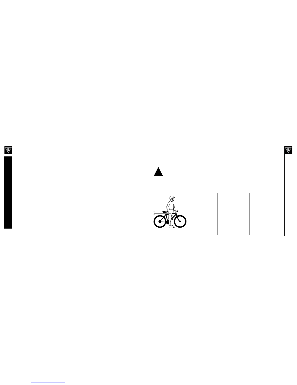
Fit
Frame sizing. . . . . . . . . . . 17
Riding position. . . . . . . . 18-19
Fork
Assembly . . . . . . . . . . . .63
Suspension . . . . . . . .121-122
Fuses . . . . . . . . . . . . . . 51
Gears . . . . . . . See "Shifters",
"Wheels - Freewheel"
Handlebar
Assembly . . . . . . . . . . 60-61
Mounted components . . . . . . .
See "Brakes", "Throttles", "Shifters",
"Power switches - Handlebar", "Bat-
tery - Gauge", "PAS", "TMM"
Headset . . . . . . . . . . . . . 98
Maintenance checklists . . 87-88
Motor . . . . . See "Currie Drive"
PAS . . . . . . . . . . . . . . . 36
Pedals. . . . . . . . . 65, 101-102
Power switches
Handlebar . . . . . . . . . . . . 50
Standard. . . . . . . . . . . . . 49
Quick releases
Front Wheel . . . . . . . . . 68-69
Seatpost . . . . . . . . . . . 66-67
. . . . . . . 25-26, 110
Saddle. . . See "Seat & seatpost"
Safety . . . . . . . . . . . . 20-29
Seat & seatpost
Assembly . . . . . . . . . . 64-65
Detailed maintenance . . . 99-100
Quick release clamp. . See "Quick
release"
Shifters
Assembly . . . . . . . . . . . .62
Gears (how to operate) . . .30-32
Grip shifters . . . . . . . . . . . 96
Shifting (how to) . . . . . . 118-119
Stem
Assembly (quill) . . . . . . . . . 60
Assembly (threadless). . . . . . 61
Maintenance. . . . . . . . . 94-95
Terminology . . . . . . . . . . 9
Throttles . . . . . . . . . . . .40
Tires . . . . . See "Wheels - Tires"
TMM . . . . . . . . . . . . . . . 37
Torque requirements. . . 124-125
Troubleshooting . . . . . 111-115
Front (bolt-on) installation . . 70-71
Front (quick release). . See "Quick
release - Front Wheel"
Freewheel . . . . . . . . . . . 109
Hub adjustament . . . . . . . .93
Maintenance. . . . . . . . . 90-93
Rear (bolt-on) installation . . 70-71
Rear wheel removal . . . . . . . 71
Tires . . . . . . . . 91-93,120-121
RMB (2008) . . . . . . . . . . . 53
RMB (2009) . . . . . . . . . . . 54
RMB 2010 (with hub motor) . . . 57
RTMB 2009 . . . . . . . . . . . 55
RTMB 2010 (with hub motor) . . 58
TMM . . . . . . . . . . . . . . . 55
Via Mezza . . . . . . . . . . . . 52

10 11
*To see detailed spare parts diagrams for each bicycle, please visit www.izipusa.com and click on the page corresponding to
your model.
RTMB (RACK TOP MOUNTED BATTERY) BICYCLES & Standard bicycle components
Electrical components in bold text
Via Rapido, Zuma Shifter
Handlebar
Brake Lever
Brake Control Cables
Front Reflector
Front Brake
Fork
Front Hub
Spokes
Stem
Head Set
Head Tube
Power Switch
Down Tube
Seat Tube
Bottom
Bracket (inside)
Rim
Tire
Chain
Crank Arm
Pedal
Chain Stay
Chain
Tire Valve
Top Tube
Seat
Seat Post
Seatpost clamp
Battery
Rear Brake
Seat Stay
Freewheel
Charger port
Rear Reflector
PAS Sensor
(behind chainring)
Hub Motor
Rear Derailleur
FOLDING BICYCLES - Super portable, with easy folding design. Perfect for camping, fits in RV's, boats and car
trunks.
*To see detailed spare parts diagrams for each bicycle, please visit www.izipusa.com and click
on the page corresponding to your model. See page 10 for common components.
Handlebar Quick Release
Handlebar Hinge
Front Fender
Rear Fender
Frame Hinge & Quick Release
Controller
Hub Motor
Battery Pack
Seat Post

12 13
ENLIGHTENED SERIES - Lightweight, hidden, Li-Ion (Lithium Ion) battery pack in a modern designed frame.
Perfect for Commuting and City Riding
TMM Sensor
(TMM models only)
Controller (inside)
Hub Motor
Battery Pack
(inside)
Control Box
Charger Port
*To see detailed spare parts diagrams for each bicycle, please visit www.izipusa.com and click
on the page corresponding to your model. See page 10 for common components.
RMB (RACK MOUNTED BATTERY) BICYCLES
RMB rack
Sealed Lead Acid Battery
Currie Drive Motor
PAS/TAG Throttle
PAS Sensor (behind chainring)
*To see detailed spare parts diagrams for each bicycle, please visit www.izipusa.com and click
on the page corresponding to your model. See page 10 for common components.

14 15
Your new bicycle was partially assembled in the factory and then partially disassembled for shipping. You
may have purchased the bicycle already fully assembled and ready to ride OR in the shipping carton in the
partially disassembled form. The following instructions will enable you to prepare your bicycle for years of
enjoyable cycling. For more details on inspection, lubrication, maintenance and adjustment of any area please
refer to the relevant sections in this manual. If you have questions about your ability to properly assemble this
unit, please consult a qualified bicycle service specialist before riding. If you need replacement parts or have
questions pertaining to assembly of your bicycle, call the service line direct at:
SERVICE AND TECHNICAL SUPPORT:
1 800 377 4532
Monday - Friday 8:00 a.m. - 4:00 p.m. (PST)
Typical Tools Required:
•Phillips head screw driver
•2.5mm,3mm,4mm,5mm6mm&8mmAllenkeys
•Adjustablewrenchora8mm,9mm,10mm,13mm,14mm,
15mm & 17mm open/box end wrenches
•A pair of pliers with cable cutting ability
manual, please refer to the torque values chart on
pages 120-121 for detailed torque requirements. Under-
or over-tightened components may loosen or break,
causing a fall.
To avoid injury, this product must be properly assembled before use. If your bicycle was
obtained assembled, we strongly recommend that you review the complete assembly
instructions and perform checks specified in this manual before riding.
!
TRICRUISER
Battery
Charger port
Fender
(front)
Fender
(rear)
Throttle
Controller
(inside)

16 17
BEFORE YOU RIDE
ABOUT THIS MANUAL
It is important for you to understand your new bicycle. By reading this manual before you go out on your first ride, you’ll know
how to get better performance, comfort, and enjoyment from your new bicycle.
It is also important that your first ride on your new bicycle is taken in a controlled environment, away from cars, obstacles, and
other cyclists.
Bicycling can be a hazardous activity even under the best of circumstances. Proper maintenance of your bicycle is your
responsibility as it helps reduce the risk of injury. This manual contains many “Warnings” and “Cautions” concerning the
consequences of failure to maintain or inspect your bicycle. Many of the warnings and cautions say “you may lose control and
fall.” Because any fall can result in serious injury or even death, we do not repeat the warning of possible injury or death where
ever the risk of falling is mentioned.
A SPECIAL NOTE FOR PARENTS
It is a tragic fact that most bicycle accidents involve children. As a parent or guardian, you bear the responsibility for the
activities and safety of your minor child. Among these responsibilities are to make sure that the bicycle which your child is
ridingisproperlyfittedtothechild;thatitisingoodrepairandsafeoperatingcondition;thatyouandyourchildhavelearned,
understand and obey not only the applicable local motor vehicle, bicycle, and traffic laws, but also the common sense rules of
safe and responsible bicycling. As a parent, you should read this manual before letting your child ride the bicycle. Please make
sure that your child always wears an ANSI, ASTM, SNELL approved bicycle helmet when riding.
CORRECT FRAME SIZE
When selecting a new bicycle, the correct choice of frame size is a very important safety consideration. Most full sized
bicycles come in a range of frame sizes. These sizes usually refer to the distance between the center of the bottom bracket
and the top of the frame seat tube.
Pleasenotethatregardlessofframesize,allIZIPbicycles(excludingtheTricruiser)haveaweightlimitof240lbs/109kg
including rider and luggage.
For safe and comfortable riding there should be clearance of no less than 1 - 2 inches between
the groin area of the intended rider and the top tube of the bicycle frame, while the rider straddles the
bicycle with both feet flat on the ground.
The ideal clearance will vary between types of bicycles and rider preference. This makes straddling the frame when
off the seat easier and safer in situations such as sudden traffic stops. Women can use a men’s style bicycle to determine the
correct size women’s model.
The following chart and diagram will help you make the correct choice. Rider leg length refers to approximate pant inseam.
PART 2 - BEFORE YOU RIDE
Approximate Rider Leg
Length
Suggested Frame Size for
-
-
Suggested frame Size for
Mountain, Hybrid, Comfort,
or Cruiser Bicycle
Frame Sizing Guide
1-2in.
!

18 19
RIDING POSITION
Seat Height
In order to obtain the most comfortable riding position and offer the
best possible pedaling efficiency, the seat height should be set
correctly in relation to the rider’s leg length. The correct saddle height
should not allow leg strain from over-extension, and the hips should
not rock from side to side when pedaling. While sitting on the bicycle
with one pedal at its lowest point, place the ball of your foot on that
pedal. The correct saddle height will allow the knee to be slightly bent
in this position. If the rider then places the heel of that foot on the
pedal, the leg should be almost straight.
Under no circumstances should the seat post project
from the frame beyond its “Minimum Insertion” or
“Maximum Extension” mark. If your seat post projects
from the frame beyond these markings, the seat post
or frame may break, which could cause you to lose
control and fall. Prior to your first ride, be sure to
tighten the seat clamp properly. A loose seat clamp
or seat post binder can cause damage to the bicycle
or can cause you to lose control and fall. Periodically
check to make sure that the seat clamp is properly
tightened.
Reach
To obtain maximum comfort, the rider should not overextend his or her
reach when riding.
To adjust this distance, the position of the seat can be altered in
relation to the seat post. (Refer to page 66 on how to adjust the seat
clamp.)
Maximum Height /
Minimum Insertion Mark
(Should not be visible)
Arms not over-
extended
Handlebar stem
height about the
same as
seat height
Pedal at
bottom position
Handlebar Height
Maximum comfort is usually obtained when the handlebar height is
equal to or slightly higher than the height of the seat. You may wish to
try different heights to find the most comfortable position.
Threadless headsets and clamp-on stems are not easily adjustable. Please refer to
page 61 for instructions on installation.
The stem’s “Minimum Insertion” mark must not be visible above the top of the
headset. If the stem is extended beyond this mark, the stem may break or damage
the fork’s steerer tube, which could cause you to lose control and fall.
Failure to properly tighten the stem binder bolt, the handlebar binder bolt, or the bar
end extension clamping bolts may compromise steering action, which could cause
you to lose control and fall. Place the front wheel of the bicycle between your legs
force. If you can twist the stem in relation to the front wheel, turn the handlebars in
relation to the stem, or turn the bar end extensions in relation to the handlebar. Prior
to riding, you must fully tighten the appropriate bolts accordingly.
Stem Wedge Bolt
Maximum Height/
Minimum Insertion
Mark
Handlebar Binder Bolt
Exceeds 2 1/2”
(64mm)
!
!

20 21
USING THE BICYCLE RACK
Safety
Please consider the following instructions before using any luggage carrier (front or rear rack) attached to your bicycle:
•The maximum capacity of rear carrying racks on Currie products is 25kg (including any attached battery).
•The maximum capacity of front racks or baskets on Currie products is 10kg.
•Do not use any bicycle luggage carrier as a child seat.
•Be sure the combined rider and luggage weight of your bicycle does not exceed the bicycle's weight limit.
•Frequently check that all fasteners related to luggage carriers are fastened securly.
•Do not modify your luggage carrier.
•Curriebicycleracksarenotdesignedtopullatrailer;donotattachatrailertoanyluggagecarrier.
•Note that bicycle handling (steering and stopping distance) may be different when the racks are carying weight.
•Ensure that any luggage is securely fitted to the bicycle rack per the manufacturer's instructions, and that no
hanging straps can get caught in the wheels.
•Be sure reflectors or lights attached to your bicycle are not obscured by your rack or attachments.
•Distribute luggage evenly on either side of the rack for even weight balance.
ATTACHMENT
The following hardware should be used to attach a rack to its respective bicycle
• RMB&RTMBbicycleracks-4xM6x14mmbolts,withlockwasher,stainlesssteel.Torqueto10Nm.
• ViaUrbanorack-4xM6x14mmbolts,withlockwasher,stainlesssteel.Torqueto10Nm.
• Skyline(optionalrack)-4xM6,14mmbolts,2xm6locknuts.Stainlesssteel.Torqueto10Nm.
• Other racks - Use included hardware, tightening attachment bolts to 10Nm.
!
This page intentionally left blank

22 23
SAFETY CHECKLIST
Before every ride, it is important to carry out the following safety checks:
1. Brakes
• Ensurefrontandrearbrakesworkproperly.
• Ensurebrakeshoepadsarenotoverwornandarecorrectlypositionedinrelationtotherims.
• Ensurebrakecontrolcablesarelubricated,correctlyadjustedanddisplaynoobviouswear.
• Ensurebrakecontrolleversarelubricatedandtightlysecuredtothehandlebar.
• Ensuretiresareinflatedtowithintherecommendedlimitasdisplayedonthetiresidewall.
• Ensuretireshavetreadandhavenobulgesorexcessivewear.
• Ensurerimsruntrueandhavenoobviouswobblesorkinks.
• Ensureallwheelspokesaretightandnotbroken.
• Checkthataxlenutsaretight.Ifyourbicycleisfittedwithquickreleaseaxles,makesurelockingleversare
correctly tensioned and in the closed position.
3. Steering
• Ensurehandlebarandstemarecorrectlyadjustedandtightened,andallowpropersteering.
• Ensurethatthehandlebarsaresetcorrectlyinrelationtotheforksandthedirectionoftravel.
• Checkthattheheadsetlockingmechanismisproperlyadjustedandtightened.
• Ifthebicycleisfittedwithhandlebarendextensions,ensuretheyareproperlypositionedandtightened.
4. Chain
• Ensurechainisoiled,cleanandrunssmoothly.
• Extracareisrequiredinwetordustyconditions.
5. Bearings
• Ensureallbearingsarelubricated,runfreelyanddisplaynoexcessmovement,grindingorrattling.
• Checkheadset,wheelbearings,pedalbearingsandbottombracketbearings.
6. Cranks and Pedals
• Ensurepedalsaresecurelytightenedtothecranks.
• Ensurecranksaresecurelytightenedtotheaxleandarenotbent.
7. Derailleurs
• Checkthatfrontandrearmechanismsareadjustedandfunctionproperly.
• Ensureshiftandbrakeleversareattachedtothehandlebar,shiftandbrake.
• Ensurederailleurs,shiftleversandshiftandbrakecablesareproperlylubricated.
8. Frame and Fork
• Checkthattheframeandforkarenotbentorbroken.
• Ifeitherarebentorbroken,theyshouldbereplaced.
9. Accessories
• Ensurethatallreflectorsareproperlyfittedandnotobscured.
• Ensureallotherfittingsonthebikeareproperlyandsecurelyfastened,andfunctioning.
• Ensuretherideriswearingahelmet.
10. Motor Drive Assembly and Throttle
• Ensureallmotordrivecomponentsarecorrectlymountedandfunctioningproperly.
11. Battery Pack
• Ensurethebatteriesareingoodoperationconditionandkeptfullycharged.

24 25
Helmets
It is strongly advised that a properly fitting, ANSI or SNELL approved,
bicycle safety helmet be worn at all times when riding your bicycle.
The correct helmet should:
- be comfortable
- be lightweight
- have good ventilation
- fit correctly
- cover forehead
Always wear a properly fitted helmet which covers the forehead when riding a bicycle. Many states
require specific safety devices. It is your responsibility to familiarize yourself with the laws of the state
where you ride and to comply with all applicable laws, including properly equipping yourself and your
bike as the law requires. Reflectors are important safety devices which are designed as an integral part
of your bicycle. Federal regulations require every bicycle to be equipped with front, rear, wheel, and
pedal reflectors. These reflectors are designed to pick up and reflect street lights and car lights in a
way that helps you to be seen and recognized as a moving bicyclist. Check reflectors and their
mounting brackets regularly to make sure they are clean, straight, unbroken and securely mounted.
Replace damaged reflectors and straighten or tighten any that are bent or loose.
Reflectors
Your bicycle is supplied with one front (white), one rear (red), two wheel (white), and four pedal (orange) reflectors. These
are an important safety and legal requirements, and should remain securely fitted and in good, clean condition at all times.
Periodically inspect all reflectors, brackets and mounting hardware for signs of wear or damage. Replace immediately if
damage is found. Some bicycles will require you to install your reflectors onto your bicycle. Please refer to the following section
for instructions on all the types of bicycle reflectors.
Fork Mount Reflector Bracket Assembly
First insert one washer onto the hex bolt and insert hex bolt through the reflector bracket and then
through the fork. Next, insert a second washer onto the bolt and thread a hex nut onto the bolt
behind the fork. Tighten bolts until snug, making sure the reflector is in an upright position. See
diagram at the right.
Front Reflector Mount with Handlebar Bracket Assembly
First attach the reflector to the reflector bracket with the reflector screw, if not already done. Next,
remove the clamp screw and open the reflector clamp bracket. Place reflector clamp bracket around
the handlebar. Tighten the clamp screw to hold reflector assembly in place. Finally, adjust the
reflector assembly in place and ensure that it is upright and facing away from the bike.
!

26 27
Seat and Handlebar Mounting Reflectors
First attach the reflector to the reflector bracket with the reflector screw, see the top
diagram. Next, remove the clamp screw and open the clamping reflector bracket.
Place clamping reflector bracket around the handlebar or seatpost. If the clamp is
too loose, insert a rubber spear inside of the clamp. Tighten the clamp screw to hold
reflector assembly in place, see the second diagram. Finally, adjust the reflector
assembly in place and ensure that it is upright and facing away from the bike.
Seatstay Mount Reflector Bracket Assembly
First insert one washer onto the hex bolt and insert hex bolt through the reflector
bracket and then through the seatstay bridge. Next, insert a second washer onto the
bolt and thread a hex nut onto the bolt behind the seatstay bridge. Tighten bolts until
snug, making sure the reflector is in an upright position. See diagram at the bottom
right.
RIDING SAFELY
General Rules
When riding obey the same road laws as all other road vehicles, including giving way to pedestrians, and stopping
at red lights and stop signs.
For further information, contact the Road Traffic Authority, police department or Department of Motor Vehicles in
your State.
Ride predictably and in a straight line. Never ride against traffic.
Use correct hand signals to indicate turning or stopping.
Ride defensively. To other road users, you may be hard to see.
Concentrate on the path ahead. Avoid pot holes, gravel, wet road markings, oil, curbs, speed bumps, drain grates
and other obstacles.
Cross train tracks at a 90 degree angle or walk your bicycle across.
Expect the unexpected such as opening car doors or cars backing out of concealed driveways.
Be extra careful at intersections and when preparing to pass other vehicles.
Familiarize yourself with all the bicycle's features. Practice gear shifts, braking, and the use of toe clips and straps,
if fitted.
If you are wearing loose pants, use leg clips or elastic bands to prevent them from being caught in the chain or
gears. Wear proper riding attire and avoid wearing open toe shoes.
Don't carry packages or passengers that will interfere with your visibility or control of the bicycle. Don't use items
that may restrict your hearing.
Do not lock up the brakes. When braking, always apply the rear brake first, then the front. The front brake is more
powerful and if it is not correctly applied, you may lose control and fall.
Maintain a comfortable stopping distance from all other riders, vehicles and objects. Safe braking distances and
forces are subject to the prevailing weather conditions.
Use designated bicycle paths if possible.
This bicycle is designed for on-road use only. It is not intended to be used for stunt riding, jumping, carrying
passengers, or riding off-road. If used incorrectly, the rider risks damage to components, injury, or death.

28 29
This hybrid electric bicycle is not
meant for use in the water (damp roads, puddles, rain, streams, etc.). Never immerse this
product in water as the electrical system may be damaged.
Although the electrical components are water resistant and there is little risk of electric shock from wet
weather, you should exercise caution and strongly consider not riding in such conditions, especially
heavy rain.
• Inwetweatheryouneedtotakeextracare.
• Brakeearlier,stoppingdistanceisupto6timeslonger.
• Decreaseyourridingspeed,avoidsuddenbrakingandtakecornerswithadditionalcaution.
• Bemorevisibleontheroad.
• Wearreflectiveclothingandusesafetylights.
• Potholesandslipperysurfacessuchaslinemarkingsandtraintracksallbecomemore
hazardous and more difficult to see when wet.
Night Riding
IT IS RECOMMENDED TO NOT RIDE AT NIGHT
• Rideatnightonlyifnecessary.Slowdownandusefamiliarroadswithstreetlighting,ifpossible.
• Ensurebicycleisequippedwithafullsetofcorrectlypositionedandcleanreflectors.
• Useaproperlyfunctioninglightingsetcomprisingofawhitefrontlampandaredrearlamp.
• Ifusingbatterypoweredlights,makesurebatteriesarewellcharged.
• Somerearlightsavailablehaveaflashingmechanismwhichenhancesvisibility.
• Wearreflectiveandlightcoloredclothing.
Pedaling Technique
• Positiontheballofyourfootonthecenterofthepedal.
• Whenpedaling,ensureyourkneesareparalleltothebicycleframe.
• Toabsorbshock,keepyourelbowsslightlybent.
• Learntooperatethegearsproperly.(Refertopages118-119)
Hill Technique
• Geardownbeforeaclimbandcontinuegearingdownasrequiredtomaintainpedalingspeed.
• Ifyoureachthelowestgearandarestruggling,standuponyourpedals.Youwillthenobtainmorepowerfrom
each pedal revolution.
• Onthedescent,usethehighgearstoavoidrapidpedaling.
• Donotexceedacomfortablespeed;maintaincontrolandtakeadditionalcare.
Cornering Technique
Brake slightly before cornering and prepare to lean your body into the corner. Maintain the inside pedal at the 12 o'clock
position and slightly point the inside knee in the direction you are turning. Keep the other leg straight, don't pedal through
fast or tight corners. While going through the turn, keep your eyes parallel to the horizon and look as far ahead of you
as possible.
Please refer to pages 116-117 for braking techniques and pages 118-119 for gear shifting techniques.
Rules for Children
Currieproductsaredesignedforridersage13orolder.Toavoidaccidents,teachchildrengoodridingskillswithanemphasis
on safety from an early age. Children should always be supervised by an adult.
1. Always wear a properly fitted helmet.
2. Do not play in driveways or the road.
3. Donotrideonbusystreets.
4. Donotrideatnight.
5. Obey all the traffic laws, especially stop signs and red lights.
6. Be aware of other road vehicles behind and nearby.
7. Before entering a street: Stop, look right, left, and right again for traffic. If there's no traffic, proceed into the roadway.
8. If riding downhill, be extra careful. Slow down using the brakes and maintain control of the steering.
9. Never take your hands off the handlebars, or your feet off the pedals when riding downhill.
The Consumer Protection Safety Commission advises that the riding of small wheel diameter bicycles at
excessive speeds can lead to instability and is not recommended. Children should be made aware of all
possible riding hazards and correct riding behavior before they take to the streets. Do not leave it up to
trial and error.
!
!
!

30 31
GEARS - HOW TO OPERATE
Derailleur Gears
Most multi-speed bicycles today are equipped with what are
known as derailleur gears. They operate using a system of levers
and mechanisms to move the drive chain between different sized
driving gears or cogs. The purpose of gears is to let you maintain
a constant, steady pedaling pace under varying conditions. This
means your riding will be less tiring without unnecessary straining
up hills or fast pedaling down hill. Bicycles come with a variety of
gearconfigurationsfrom5to30speeds.A5or6speedbicyclewill
typically have a single front chainwheel, a rear derailleur, and 5 or 6
cogs on the rear hub. Bicycles with more gears will additionally have
afrontderailleur,afrontchainwheelwith2-3cogs,andupto10cogs
on the rear hub.
Operating Principles
No matter how many gears, the operating principles are the same.
The front derailleur is operated by the left shift lever and the rear
derailleur by the right. To operate you must be pedaling forward. You
can not shift derailleur gears when you are stopped or when pedaling
backwards. Before shifting ease up on your pedaling pressure. For
a smooth gear change when approaching a hill, shift to a lower gear
BEFORE your pedaling speed slows down too much. When coming
to a stop, shift to a lower gear first so it will be easier when you start
riding again. If, after selecting a new gear position, you hear a slight
rubbing noise from the front or rear gears, some adjustments may be
necessary. Gently adjust the appropriate shifter using the barrel
adjusters until the noise goes away. For optimal performance and
extended chain life, it is recommended that you avoid using the
extreme combinations of gear positions (Refer to diagram on page
31)forextendedperiods.Itisrecommendedthatatrainedbicycle
technician perform all adjustments to the shifters and derailleurs.
Drivetrain
Front Derailleur
Guide Pulley
Rear Derailleur
Front Chainwheels
Crank Arm
Pedal
Derailleur Control
Cable
Freewheel
Cogs
Hand Grip Shifters
Some bicycles are equipped with a shifting mechanism called Grip
Shift™, which is built into the handlebar grips and does not make use
of separate levers. The actuating mechanism is built into the inside
part of the grip so that the hand and palm wrap around them naturally.
To select a lower gear, twist the left shifter toward you to engage a
larger rear cog. You can shift one gear at a time by moving the Grip
Shift™ one click, or through multiple gears by continued twisting. To
select a higher gear, twist the left shifter forward or away from you to
engage a smaller rear cog. Single shifts can be achieved by twisting
one click at a time and multiple shifts by larger twists.
Front Low Gear Rear Low Gear
Front High Gear Rear High Gear
123456
3
1
High Middle Low
2
These combinations are
NOT RECOMMENDED for
optimal performance.
123456
2
High
1
Low
These combinations are
NOT RECOMMENDED for
optimal performance.

32 33
Below the Bar Shifters
Many mountain style bicycles now use a shift lever arrangement
mounted on the underside of the handlebars, which use two levers
operated by the thumb and index finger. To select a lower gear push the
larger (lower) right shifter with your thumb to engage a larger rear cog.
One firm push shifts the chain one cog, continuing to push will move
the chain over multiple cogs. Pulling the smaller (upper) left shifter with
your index finger moves the chain from a larger to a smaller chainwheel.
To select a higher gear pull the smaller (upper) right lever with your
index finger to engage a smaller rear cog. Pushing the larger (lower)
left lever with your thumb will move the chain from a smaller to a larger
chainwheel. Please refer to pages 118-119 for additional instructions in
“How Things Work”.
Left hand lever Right hand lever BICYCLE CARE
Basic Maintenance
The following procedures will help you maintain your hybrid electric bicycle for years of enjoyable riding.
Properly maintain the batteries by keeping them fully charged when not in use.
Do not ride your hybrid electrical bicycle in the water (damp roads, puddles, rain, streams, etc.) and never immerse it in water
as the electrical system may be damaged.
Periodically check the wiring and connectors to ensure there is no damage and the connectors have good continuity.
For painted frames, dust the surface and remove any loose dirt with a dry cloth. To clean, wipe with a damp cloth soaked in
a mild detergent mixture. Dry with a cloth and polish with car or furniture wax. Use soap and water to clean plastic parts and
rubber tires. Chrome plated bikes should be wiped over with a rust preventative fluid.
Store your bicycle under shelter. Avoid leaving it in the rain or exposed to corrosive materials.
Riding on the beach or in coastal areas exposes your bicycle to salt which is very corrosive. Wash your bicycle frequently
and wipe or spray all unpainted parts with an anti-rust treatment. Make sure wheel rims are dry so braking performance is not
affected. After rain, dry your bicycle and apply anti-rust treatment.
If the hub and bottom bracket bearings of your bicycle have been submerged in water, they should be taken out and
re-greased. This will prevent accelerated bearing deterioration.
If paint has become scratched or chipped to the metal, use touch up paint to prevent rust. Clear nail polish can also be used as
a preventative measure.
Regularly clean and lubricate all moving parts, tighten components and make adjustments as required. (Refer to Parts
5 and 6 of this manual for further details).
The use of alloy components and BED, SATIN and TITANIUM surface treatments minimizes the number of places
where rust can surface.

35
34
Storage
Keep your bicycle in a dry location away from the weather and the sun.
Direct sunlight may cause paint to fade or rubber and plastic parts to
crack. Before storing your bicycle for a long period of time, clean and
lubricate all components and wax the frame. Deflate the tires to half
pressure and hang the bicycle off the ground. Charge your batteries and
make sure they are protected from water. Batteries should be charged
every30(LithiumIon)or90(SLA)daystoavoidcapacityloss.Don'tcover
the bicycle with plastic as "sweating” will result which may cause rusting.
Please notice that your bicycle warranty does not cover paint damage
(except as outlined in the warranty section of this manual), rust, corrosion,
dry rot or theft.
Security
It is advisable that the following steps be taken to prepare for and help
prevent possible theft.
1. Maintain a record of the bicycle’s serial number, generally
located on the frame underneath the bottom bracket or on the
head tube.
2. Register the bicycle with the local police.
3. Investinahighqualitybicyclelockthatwillresisthacksaws
and bolt cutters. Always lock your bicycle to an immovable
object if it is left unattended.
ELECTRONIC COMPONENTS
Battery Gauge
When the throttle or sensor is engaged (powering the motor) and the
bicycle is in motion, the LEDs on the battery gauge (on the throttle or
separate unit) indicate instantaneous line voltage as measured at the
battery terminals – not the available energy in the battery pack.
The line voltage willwwing out from a dead stop, or going up a steep hill,
the motor will be under a high load and may show a reduced number of
LEDs or show the “Yellow” or even “Red” LED.
When the throttle is disengaged (i.e. no power to the motor due to
the bicycle being stationary or coasting) the LEDs on the throttle will
indicate the voltage of the battery pack. The voltage of the battery pack
will rise when no load is on the motor. The best indication of how much
battery life is remaining is to check the throttle LEDs, after reaching
cruisingspeed,onaatstraightroadasthiswillallowthebattery
voltage to stabilize and give a much more accurate reading.
TAG Throttle with
Battery Gauge
PAS / TAG
with Battery Gauge
PART 3 - ELECTRICAL COMPONENTS
TMM Control Box
with Battery Gauge

36 37
Press to turn on the bicycle
Afterpressing‘Power’,alleightmeterlightswillashin
sequence, indicating that the bike is ready to ride.
If your bike has an additional physical switch or battery
selector located behind or in front of the batteries, be sure
it is turned to the proper position before pressing ‘Power’.
The lights indicate
remaining charge
Thebatterygaugeprovidesfiveindicationsofbattery
level.
When the battery is depleted to the point of automatic
shutoff, the lowest gauge light will blink indicating the
need to recharge immediately. Of course, the bicycle can
still be ridden with the system turned off.
Due to the way the battery gauge measures charge, the
indicatorlightsmayuctuatewhileridingbasedonthe
motor’s current load.
The best indication of remaining battery life is to check the
battery level gauge LEDs after reaching cruising speed
onasmooth,at,straightroad.Thiswillallowthebattery
voltage to stabilize and will give a much more accurate
reading.
Press to turn on the bicycle
Do not put any pressure on the pedals when turning the bicycle
on. Doing so may affect the TMM sensor calibration (the TMM
sensor is re-calibrated each and every time the power is turned
on).
If your bike has an additional physical switch or battery selector
located behind or in front of the batteries, be sure it is turned to
the proper position before pressing ‘Power’.
Afterpressing‘ON/OFF’,alltenmeterlightswillashinse-
quence, indicating that the bike is ready to ride.
Toturnthebicycleoff,holdthe'ON/OFF'buttonforabout3
seconds.
The lights indicate remaining
charge
Thebatterygaugeprovidesfiveindicationsofbatterylevel.
When the battery is depleted to the point of automatic shutoff,
the lowest gauge light will blink indicating the need to recharge
immediately. Of course, the bicycle can still be ridden with the
system turned off.
Due to the way the battery gauge measures charge, the
indicatorlightsmayuctuatewhileridingbasedonthemotor’s
current load. This behavior does not apply to the IZIP Ultra,
which uses state-of-charge (SoC) information from the battery
pack to display very accurate battery charge information.
The best indication of remaining battery life is to check the
battery level gauge LEDs after reaching cruising speed on a
smooth,at,straightroad.Thiswillallowthebatteryvoltageto
stabilize and will give a much more accurate reading.
The button controls motor
assist power
The PAS system provides three assist levels, which you
cancyclebetweenusingthe‘Assist+/-’button.
Each level of assist corresponds to a maximum motor
speed;atlevel3,themotorrunsatfullpower.Overall
range decreases at higher power levels.
The system defaults to the lowest assist level at startup.
The motor will activate when the system senses the rider
pedaling. It is not possible to activate the motor without
turning the cranks.
Torque Measurement
Method
The and buttons control motor assist
power
TheTMMsystemprovidesfiveassistlevelswhichyoucan
choosebetweenusingthe'+’and'-'buttons.
Each increasing level of assist gives more motor power, but
also decreases overall range.
Thesystemdefaultstoassistlevel3atstartup.
The motor will activate when the system senses the rider
applying pressure to the pedals. It is not possible to activate
the motor without rider input. The 500 Watt IZIP Ultra has an
additional safety sensor that requires the bicycle to be rolling
forward before the motor is activated.

38 39
Press to turn on the bicycle
Afterpressing‘Power’,alltenmeterlightswillashinse-
quence, indicating that the bike is ready to ride.
To turn the bicycle off, hold the 'ON/OFF' button for about
3seconds.
E3Ultra:
Do not put any pressure on the pedals during startup.
Doing so may affect the pedal-force sensor calibration (the
pedal-force sensor’s zero-point is re-calibrated each and
every time the power is turned on).
The BATTERY lights display remaining
charge
Themeterboxhasfivebatterylevelindicators.Thebat-
tery pack reports state-of-charge (SoC) information to
the controller and the meter box uses this information to
display the battery level with high accuracy.
When the battery is depleted to the point of automatic
shutoff, the lowest gauge light will blink indicating the need
to recharge immediately. Of course, the bicycle can still be
ridden with the system turned off.
PAS Mode: the ‘-’ and ‘+’ buttons control
motor assist power
PAS mode provides three levels of assist. You can choose
betweenthembypressingthe‘+’and‘-’buttons.Each
increasing level of assist gives more motor power, but
decreases overall range. The system defaults to assist
level 2 at startup. Regardless of the mode setting, the
Theamountofpedalpressureandtheamountofmotorassistareproportional;
harder pedaling will result in the motor providing more assistance. The throttle
acts as a “boost” once the bike is rolling, and overrides the pedal sensor when
applied.
TAG Mode
InTAGmode,thepedalsensor(E3Metro)orpressuresensor(E3Ultra)usedfor
PAS mode operation is disabled, and the bike responds only to throttle input. Just
twistthethrottletoapply0-100%ofmotorpower.The‘-’and‘+’buttonsarenot
used in this mode.
throttle is always able to provide 100% power.
E3Metro:
The motor will activate when the system senses the rider pedaling.
It is not possible to activate the motor without turning the cranks.
The throttle can act as a “boost” once the bike is rolling, but if
crank movement is discontinued, power will drop away within 1-2
seconds with or without throttle use.
E3Ultra:
The motor will activate when the system senses the rider applying
pressure to the cranks. It is not possible to activate the motor
otherwise in PAS mode. Also the bicycle must be rolling forward at
about3km/hbeforethemotorwillactivate.Thissafetyfeatureis
intended to prevent unintentional acceleration.
Mode Select (green button)
Other manuals for eZip Trailz
1
This manual suits for next models
8
Table of contents
Other Currie tech Bicycle manuals

Currie tech
Currie tech IZIP EXPRESS User manual

Currie tech
Currie tech IZIP User manual

Currie tech
Currie tech IZIP E3Metro Parts list manual

Currie tech
Currie tech Peak User manual

Currie tech
Currie tech eZip TRICRUISER User manual

Currie tech
Currie tech E-FolderCTI-B-30 User manual

Currie tech
Currie tech eZip Trailz User manual

Currie tech
Currie tech IZIP VIA URBANO User manual

Currie tech
Currie tech IZIP User manual

Currie tech
Currie tech IZIP User manual