Currie tech eZip TRICRUISER User manual


Currie Technologies Technical and Customer Service 1-800-377-4532
2
Helpful Tools:
Included in your parts box:
• Scissors(forcuttingzip-ties)
• Bicyclegrease
• Phillips-headscrewdriver
• Allenwrenches:4,5,&6mm
• Open-endwrenches:9,10,14,15,&17mm
oradjustablecrescentwrench
• Needle-nosepliers
• Pedals
• Quickreleaseskewer
• Reectors(ifnotalreadyinstalled)
• Toolkit(4+5mmcomboAllenwrench,
13+15mmcomboopen-endwrench)
Assembly will take 1 - 2 hours
Note: Whenworkingonyourtricycleasinstructedbythisguide,pleaserefertothetorquevalueschart(Pages18and19)fordetailedtorquerequire-
ments.Under-orover-tightenedcomponentsmayloosenorbreak,causingafall.
Stepsinthisguidethatcallfortheuseofbicyclegreasedosointheinterestofkeepingyourtricycleinworkingconditionforaslongaspossible.Grease
isnotabsolutelyvitaltotheassemblyofthisproduct,butfailuretoapplyitasdirectedcouldcausepartstoseizeovertimeandirreparablydamagethe
frameorcomponents.
Becausetricyclepartstendtobegreasy,itisrecommendedthatyoulaydownatarporsheettoprotectyouroorifassemblingthetrikeindoors.
Itisbesttoremovetheprotectivepackagingduringtheassemblyprocessonlyasneeded,leavingsomeintacttoprotectthetrikeduringassembly.
Duringassemblyitmaybehelpfultoreferencethephotosonthecoverofthisguideifyouareunsureofanysteps.
Pleasetakethetimetoreadthebatterycareandstoragesectionofyourmanualforusefulinformationonprolongingthelifeofyourbattery.
Assembly Tools

Currie Technologies Technical and Customer Service 1-800-377-4532 3
Pleaserecycle
packagingmaterials!
A
B
Unpacking and Preparation
Seatpost
1. Carefully remove the rear end sub-assembly and the main
frame sub-assembly from their boxes;youshouldhaveafriendhelp
youwiththis,asthesepartsareheavy.Findthepartsboxpackagedwiththe
mainframesub-assemblyandsetitasidefornow.
2. Remove the battery from the main frame sub-assembly (seethe
Batterysectiononpage14formoreinformation).
Begin charging the battery—thiswilltakeabout10hours.Thebattery
isinsidethemainframesub-assembly.Thechargerisinasmallwhitebox,
packagedwiththemainframesub-assembly.Asolidredorblinkinggreen
lightonthecharger(dependingonmodel)indicatesthebatteryischarging
properly.Asolidgreenlightindicatesthatthechargerhasenteredtrickle
chargemode,andyourbatteryisatleast80%full.Formaximumrange,
pleasechargeforthefullrecommendedtimeperiod(8-10hours).
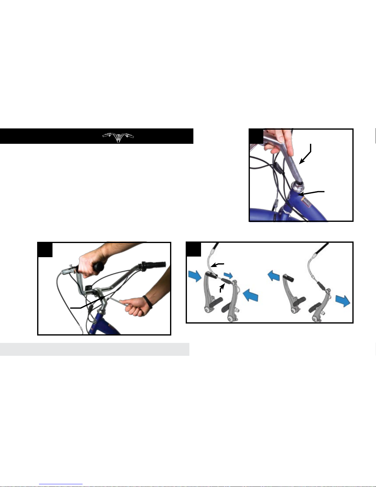
3. Apply grease to the inside of the seat tube,theninsert the
seatpostandclose the quick release tightly (Photo B).Itwillhelp
duringthenextstepsifyoulowerthesaddleallthewaydown;itcanbe
adjustedtoacomfortableheightbeforeyourrstride.
Refertotheappendixtothisguideformoreinformationontheuseand
adjustmentofquickreleaselevers.It is vital to your safety that you
understand and properly secure this lever!
Battery plugged in to charger

Currie Technologies Technical and Customer Service 1-800-377-4532
4
4. Locate the stem,attachedtothecenterofthehandlebars.Remove
the black plastic capcoveringitsend,theninsert the stem into the
tricycle’s head tube.Makesuretheforkisrotatedsothefrontbrake
facesawayfromtheframe.Alignthehandlebarstobeperpendiculartothe
fork,then tighten the wedge bolt on top of the stem(PhotoD).It is
extremely important that you properly tighten the wedge bolt.Leaving
thisbolttooloosecanresultinthehandlebarsturningawayfromthewheel,
causingacrash.Seethe“Beforeyourrstride”sectionofthisguideformore
information.
5. Release the front brakebypullingbacktherubberboot,squeezingthe
brakearmstogether,thenremovingthe“noodle”fromitsholder(PhotoE).
Thiswillallowyoutoinstallthefrontwheellater.Youwillneedtoreattach
thebrakebyreversingthissteponcethefrontwheelandfrontfenderare
installed.
C
D
Handlebars and Stem
Pull back rubber boot. Squeeze brake arms
inward and pull “noodle” out of holder.
Boot
Noodle
E
Stem
Wedge bolt
Head tube

Currie Technologies Technical and Customer Service 1-800-377-4532 5
F
H
6. Turnthetricycleupsidedown,soitsweightrestsontheseatand
handlebars.Becarefulnottodamagetheseatorthehandlebar-mounted
brakesandthrottle.Makesurethebatteryisnotinstalledintheframe!
7. Fully loosen, but do not remove, the four carriage boltsshownin
PhotoFusinga17mmwrench.
8. Toassistinthenextstep, make sure the heads of the bolts
attached to the rear end sub-assembly are pushed ush with the
frame(DiagramG-1).Theboltsattachedtotheframeitselfshouldbe
pushedintheoppositedirection(DiagramG-2).
9. Slide the rear-end assembly into the main frame (PhotoH),
makingsurethewashersattachedtothefourcarriageboltssittotheoutside
oftheframe,againstthenuts. Make sure the rear axle is perpendicular
to the frame,butdonottightentheboltsyet.
GTop view (Tricycle upside down)
Rear
Bolt head ush (1) Nut ush (2)
Front
Rear end

Currie Technologies Technical and Customer Service 1-800-377-4532
6
L
10. Locate the extra chain wrapped around the rear axle,hereafter
referredtoasthe“transferchain.”
11. Findthetransferchain’smasterlink(Photo I).Thislinkisdesignedto
beeasilydetached.Using a pair of needle-nose pliers, slide the link’s
face plate completely off (PhotoJ).Theentirelinkwillthenslideaway
fromthechain,breakingthechaininhalf(DiagramK).
12. Wrap the transfer chain around the two gears shown to
connectthefrontandrearsub-assemblies.
I
JK
Transfer chain connects front and rear
sub-assemblies

Currie Technologies Technical and Customer Service 1-800-377-4532 7
M
N
13. Close the transfer chainbyreattachingthemasterlink,then
reversingstep11tosnaponthefaceplate.
14. Make sure the front and rear frame sections are perpendicular
to each other.Adjust the tension of the transfer chainbyslidingthe
rearendtowardsorawayfromthemainframe;whenproperlyadjustedthe
chainshouldhaveabout1/4inofverticalplay.Tighten the four carriage
bolts from step 7,thenre-checktherear-endalignmentandtransferchain
tension.
Rear axle
Main Frame
15. Locatethefrontwheel–Itcanbedifferentiatedfromtherearwheels
becauseitistheonlyonewithhardwarealreadyattachedtoitsaxle.
Remove the black plastic dropout protector from the tricycle’s
fork and the two disc-shaped axle protectors from the front wheel,
thenloosen the hardware attached to the front wheelandinsert
the wheel into the forkasshowninPhotoN.Tighten the axle nuts
securelywitha15mmwrench.
Front Wheel
Transfer chain

Currie Technologies Technical and Customer Service 1-800-377-4532
8
16. Remove the hardware from the rear axles(oneortwowashers
andtwonuts)slide the rear wheels onto their respective axles.Notice
thattheonerearaxlehasaatsection,whiletheotherdoesnot—this
preventsthewheelsfrombeingincorrectlyinstalled.
17. Attach the rear wheel hardwareasshowninDiagramP.Tighten
the four axle nuts securely witha17mmwrench.
Rear Wheels O
Q
P
Left-side axle
(note at section)
Hub (left)
Hub (right) Washer
Washer (large)
Washer (small)
Nut
Nut
Locknut
Locknut Left-side rear
wheel installed
(no nuts or washers)

Currie Technologies Technical and Customer Service 1-800-377-4532 9
Motor Connection
R
S
TU
18. Flip the tricycle right-side-upfornalassembly.
19. Open the controller boxonthetricycle’sleftside(whenviewed
frombehind)withaPhillips-headscrewdriver(PhotoR),thenplug the
motor into the open connector showninPhotoS.
20. Route the motor wire along the frameusingziptiestosecureit
totheframe(PhotoT).Close the controller box,routingthewiresoutthe
gapinthebottomoftheboxasshowninPhotoU.
Wires exiting
controller box
through gap

Currie Technologies Technical and Customer Service 1-800-377-4532
10
V
W X
21. Locatethetworearfenders(withattachedredreectors).Thefender
hardwareisalreadyattachedtotherearendofthetricycle.Usingthis
hardware, install the fendersasshowninPhotoV,withaPhillips-head
screwdriverandan8mmwrench.
22. Fold the basket into shape,securingthecornerswiththeattached
silverpins(PhotoW).
23. Attach the rear basketusingaPhillips-headscrewdriveranda
10mmwrenchtotightenthefourbolts(PhotoX).Tomakesurethebasketis
alignedproperly,youshouldlooselyfastenallfourboltsbeforetighteningany
ofthem
Fenders & Basket

Currie Technologies Technical and Customer Service 1-800-377-4532 11
Y
ZAa
24. Install the front fender usingthethreeboltsshowninPhotoY,then
close the front brake(seestep5&PhotoE onpage4).Makesurethe
fenderdoesnotinterferewithbrakeoperation(PhotoZ).
25. Find the pedals in your parts box. Grease the threadsand
thread them securely into the crank arms using a 15mm open-end
wrench (PhotoAa).Notethatthepedalshaveoppositethreaddirections
andmustgoonaspecicsideofthebicycle.Thepedalmeantforthedrive-
side(thesideofthebicyclewiththemainchainandgears)hasastandard
thread,whichistightenedclockwise.Thenon-drive-sidepedalhasareverse,
non-standardthread.Itmustbeturnedcounter-clockwisetobescrewedin.
Pedals

Currie Technologies Technical and Customer Service 1-800-377-4532
12
Ac
26. Flip the seat forwardusingthereleaseleverbelowit.Thisallows
accesstothebatterycompartment.
27. Whilepullingthelockingpinoutward(Ac-1),slide the battery into
the frame(Ac-2).Oncethebatteryisseated,releasethepintolockthe
packinplace,thenconnect the battery plug(Ac-3).
28. Adjust your front and rear brakes.Yourbrakesmaynotbe
fullyadjustedfromthefactory;refertoyourowner’smanualfordetailed
instructionsonbrakeadjustmentorconsultaprofessionalbikemechanicif
youarenotcomfortablemakingtheseadjustmentsyourself.Do not attempt
to ride your bicycle without properly adjusting the brakes!
Ab
Release
locking pin (1)
Slide battery
into frame (2)
Plug in battery (3)

Currie Technologies Technical and Customer Service 1-800-377-4532 13
Thispageintentionallyleftblank

14 Currie Technologies Technical and Customer Service 1-800-377-4532
14
Ad
Installation:
Yourtricyclecomeswitha36voltSealedLeadAcid(SLA)battery.Toinstallthebattery,simplyslideitintothe
tricycleframewhilepullingthebatterylockingpinshowninphotoAd.
Thistypeofbatterydoesnothavea‘memory’,andridingonapartialchargewillnotharmthebatteryinanyway.
Rechargetimeforthisbatteryis8-10hourstoreachafullcharge.
Ae
To turn your tricycle on, simply toggle the battery’s ON/OFF switch to
the ON position. The lights on the throttle (Photo Ae) will illuminate,
indicatingthechargelevelofthebattery.
TheTricruiserusestheCurrie“TwistandGo”(TAG)system.Simplytwist
thehandlebar-mountedthrottletowardsyoutopowerupthemotor.
Operation
Battery
Batery locking pin
(pull to release battery)

15
Currie Technologies Technical and Customer Service 1-800-377-4532 15
• Remove all remaining packaging on the trike.
• Check the operation of your front and rear brakesbypushingthetrikeforwardandoperatingthebrakelevers.
• Check the tightness of all nuts and bolts,especiallythestemboltsandtheboltssecuringthebrakeleversandshifterstothehandlebars.
• Make sure the stem’s wedge bolt is tight.Checkthatitistightenedproperlybystandingoverthefrontwheel,holdingitwithyourthighs,then
tryingtoturnthehandlebars.Ifthehandlebarscanbeturnedindependentlyofthewheel,thewedgeboltmustbetightenedfurther.
• Make sure your front wheel is secure in the frame.
• Make sure your tires are lled to the pressure recommended on the sidewall. Over-or under-inatedtirescanblowofftherimandcause
afall.Werecommendusingabicyclepumpwithpressuregauge.
Trike won’t turn on (no lights
on throttle)
•Powerplugnotfullyconnectedtobattery—checkbatteryconnection.
•Batterynotcharged.
Brakes not effective •Re-adjustbrakes,referringtoowner’smanual.Donotrideyour
tricyclewithoutproperlyadjustedbrakes!
Gears/chain make clicking or
grinding noises while riding
•Checkthechaintensionbetweenthefrontandrearendsofthe
tricycle(setinstep14)
Can someone help me with...? •CalltheCurrieTechnologiestechnicalandcustomerservice
departmentat1-800-377-4532.
Refer to owner’s manual for detailed troubleshooting chart
Before Your First Ride...

16 Currie Technologies Technical and Customer Service 1-800-377-4532
16
ManyIzipandEzipbicyclemodelsusequickrelease(QR)leverstofacilitatecommontaskssuchasfrontwheelremovalandseatheightadjustment.
Whenproperlyadjusted,quickreleaseleversarebothsafeandconvenient,butyoumustunderstandandapplythecorrecttechniquetoadjustthem
properlybeforeridingyourbicycletopreventseriousinjuryordeathfromafall.
Quickreleaseleversuseacamactiontoclampthewheelorothercomponentsinplace.Becauseoftheiradjustablenature,itiscriticalthatyou
understandhowtheywork,howtousethemproperly,andhowmuchforceyouneedtoapplytosecurethem.
Warning: Thefullforceofthecamactionisneededtoclampthewheelsecurely.Holdingthenutwithonehandandturningtheleverlikeawingnutis
NOTasafeoreffectivewaytocloseaquickreleaseandwillnotclampthewheelorothercomponentssafely.
QUICK RELEASE USAGE
Ridingwithanimproperlyadjustedwheelquickreleasecanallowthewheeltowobbleorfalloffthebicycle,whichcancauseseriousinjuryordeath.
Therefore,itisessentialthatyou:
1.Askyourdealeroralocalbikeshoptohelpyoumakesureyouknowhowtoinstallandremoveyourwheelssafely.
2.Understandandapplythecorrecttechniqueforclampingyourwheelinplacewithaquickrelease.
3.Eachtime,beforeyouridethebike,checkthatthewheelissecurelyclamped.
Appendix: Quick Release Levers

17
Currie Technologies Technical and Customer Service 1-800-377-4532 17
Adjusting a quick release seatpost clamp
Inaseatpostquickreleasesystem,theseatpostisclampedinplacebytheforceofthequick
releasecampushingagainstonesideoftheclampandpullingthetensionadjustingnut,
bywayoftheskewer,againsttheother.Theamountofclampingforceiscontrolledbythe
tensionadjustingnut.Turningthetensionadjustingnutclockwisewhilekeepingthecamlever
fromrotatingincreasesclampingforce;turningitcounterclockwisewhilekeepingthecam
leverfromrotatingreducesclampingforce.Lessthanhalfaturnofthetensionadjustingnut
canmakethedifferencebetweensafeclampingforceandunsafeclampingforce.
1. WiththequickreleaseclampintheOPENposition,inserttheseatpost,withsaddle
attached,intothebicycle’sseattube.
2. SwingthequickreleaseleverintotheCLOSEDposition.
3. Grabthesaddlewithbothhandsandattempttorotateit(andthusrotatetheseatpostin
theseattube).
4. Ifyouareabletoforcetheseatpostoutofalignmentwiththeframe,theseatpostclamp
needstobeadjusted.HoldingthequickreleaseleverintheOPENpositionwithone
hand,tightenthetensionadjustingnutwithyourotherhandabout1/2turnclockwise.
5. AttempttoswingtheleverintotheCLOSEDposition.Ifthelevercannotbepushedall
thewaytotheCLOSEDposition(gureb),returnthelevertotheOPENposition,then
turnthetensionadjustingnutcounterclockwiseone-quarterturnandtrytighteningthe
leveragain.Repeatsteps3,4&5untilproperquickreleasetensionisachieved.
Tension adjusting
nut
open
Closed

18 Currie Technologies Technical and Customer Service 1-800-377-4532
18
Component Recommended Torque Value (in-lb) Nm
Headset, Handlebar, Seat area
Seatxingbolt(seatrailbinder) 174 - 347 19.7 - 39.2
Stemhandlebarbinderbolts(2) 174 - 260 19.7 - 29.4
Stemwedge(binder)bolt-quilltypefor
threadedheadset 174 - 260 19.7 - 29.4
Threadedheadsetlocknut 130 - 150 14.7 - 16.9
Threadlessstemclampbolts 120 - 144 13.6 - 16.3
Crankset, Bottom Bracket, Pedal area
Chainringbolt(aluminum) 44 - 88 5.0 - 9.9
Chainringbolt(steel) 70 - 95 7.9 - 10.7
Crankbolts 305 - 391 34.5 - 44.2
Pedal(intocrank) 307 - 350 34.7 - 39.5
Derailleur, Shift lever area
Frontderailleurcablepinch 44 - 60 5.0 - 6.8
Frontderailleurclampmount 44 - 60 5.0 - 6.8
Rearderailleurcablepinchbolt 35 - 45 4.0 - 5.1
Rearderailleurmountingbolt 70 - 86 7.9 - 9.7
Shiftlever(MTBthumb-type) 22 - 26 2.5 - 2.9
Shiftlever(SRAM“grip-shift”type) 17 1.9
Bicycle Torque Values

19
Currie Technologies Technical and Customer Service 1-800-377-4532 19
Component Recommended Torque Value (in-lb) Nm
Wheel area
Wheelaxlenutstoframe/fork 260 - 390 29.4 - 44.1
Brakes
Brakecablepinchbolt(linearpull) 53 - 69 6.0 - 7.8
Brakecaliper(linearpull)toframe/fork 45 - 60 5.1 - 6.8
Brakelever(MTBtype) 53 - 69 6.0 - 7.8
Brakepadtocaliper 50 - 70 5.6 - 7.9
Discbrakecalipermount 60 - 90 6.8 - 10.2
Discrotortohub 35 - 55 4.0 - 6.2
Bicycle Torque Values, ctd.

9453OwensmouthAve,Chatsworth,CA91311
Phone:+1800.377.4532Fax:+1818.734.8199
www.currietech.com
Table of contents
Other Currie tech Bicycle manuals

Currie tech
Currie tech eZip Trailz User manual

Currie tech
Currie tech Peak User manual

Currie tech
Currie tech IZIP User manual

Currie tech
Currie tech eFlow E3Nitro User manual

Currie tech
Currie tech IZIP User manual

Currie tech
Currie tech IZIP VIA URBANO User manual

Currie tech
Currie tech IZIP EXPRESS User manual

Currie tech
Currie tech E-FolderCTI-B-30 User manual

Currie tech
Currie tech E3 Path+ User manual

Currie tech
Currie tech IZIP User manual