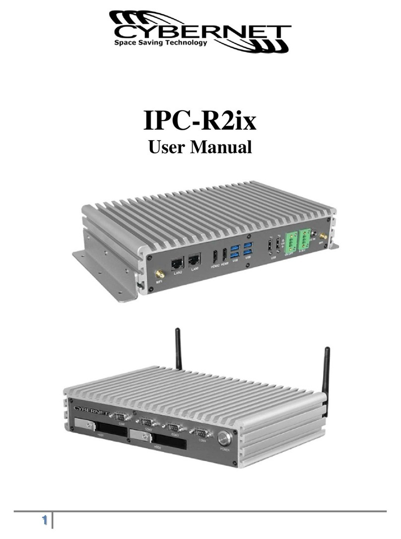
Cybernet IPC-R1ix User manual

USER
Manual
USER
Manual
IPC-R1ix
Fanless Robust Computing System With 4 PCI/PCIe Slots,
3rd Gen. Intel® Core™ i7/ i5/ i3 Mobile Processor

This manual is released by Cybernet for reference purpose only. All
does not represent commitment of Cybernet. Cybernet shall not be liable for
direct, indirect, special, incidental, or consequential damages arising out of the
use of the product or documentation, nor for any infringements upon the rights
of third parties, which may result from such use.
This equipment has been tested and found to comply with the limits for a Class
A digital device, pursuant to part 15 of the FCC Rules. These limits are designed
to provide reasonable protection against harmful interference when the
equipment is operated in a commercial environment. This equipment generates,
uses, and can radiate radio frequency energy and, if not installed and used in
accordance with the instruction manual, may cause harmful interference to radio
communications. Operation of this equipment in a residential area is likely to
cause harmful interference in which case the user will be required to correct the
interference at his own expense.
FCC
The product (s) described in this manual complies with all applicable European
Union (CE) directives if it has a CE marking. For computer systems to
remain CE compliant, only CE-compliant parts may be used. Maintaining CE
compliance also requires proper cable and cabling techniques.
CE
This document contains proprietary information protected by copyright. No part
of this publication may be reproduced in any form or by any means, electric,
photocopying, recording or otherwise, without prior written authorization
by Cybernet. The rights of all the brand names, product names and
trademarks belong to their respective owners.
Declaimer
Declaration of Conformity
Copyright and Trademarks
Part Number Description Expansion Slots
IPC-R1ix Fan-less Robust Computing System, 2 Slots 1 PCIe x4 +
1 PCIe x16
Order Information

v
Part Number Description
i7-3610QE Ivy Bridge 3rd Gen Intel® Mobile Quad-Core™ i7 Processor
i5-3610ME Ivy Bridge 3rd Gen Intel® Mobile Core™ i5 Processor
i3-3120ME Ivy Bridge 3rd Gen Intel® Mobile Core™ i3 Processor
M340S-W28M1 DDR3 4GB 1333 | 1066MHz RAM, Micron ® Chip,
Wide Temperature -40°C ~ +85°C
4GB RAM
8GB RAM
PWA-160W-WT 160W, 24V, 85VAC to 264VAC Power Adaptor with 3-pin
Terminal Block, Wide Temperature -30°C to +70°C
PWA-120W 120W, 24V, 90VAC to 264VAC Power Adapter with 3-pin
Terminal Block
SCSI-20P-100 20-pin SCSI Cable, 1M
TMB-SCSI-20P Terminal Board with One 20-pin SCSI Connector and
DIN-Rail Mounting
Optional Accessories

vi
Table of Contents
CHAPTER 1 GENERAL INTRODUCTION 1
1.1 Overview 1
2
2
1.3 Supported CPU List 4
1.4 Mechanical Dimension 5
CHAPTER 2 GETTING TO KNOW YOUR IPC-R1ix 06
2.1 Packing List 06
2.2 Front Panel I/O Functions 06
2.2.1 Power Button 07
2.2.2 Rest Tact Switch 08
2.2.3 Power, HDD LED Indicator 08
2.2.4 Dual Isolated 8 DI/ 8 DO 09
2.2.5 Serial Port, COM 1, COM 3, COM 4 12
2.2.6 USB 2.0 Port 13
2.2.7 Serial Port, COM 2 14
2.2.8 USB 3.0 Port 15
2.2.9 10/100/1000 Mbps Ethernet Port 15
2.2.10 DisplayPort 17
2.2.11 DVI-D Connector/ HDMI Connector 17
2.2.12 VGA Connector 18
2.2.13 Audio Connector 19
2.2.14 DC-in Power Terminal Block 19
20
2.3 Main Board Expansion Connectors 21
2.3.1 J2 Miscellaneous Pin Header 23
2.3.2 CFast Card 24
2.3.3 CN9, CN11, J3 LVDS 26
2.3.4 CN16, CN17 SATA-III Connector 29
IPC-R1ix

vii
2.3.5 CN18, CN19 SATA-II Connector 30
2.3.6 CN14, CN20 SATA Power Connector 31
2.3.7 SATA DOM Power Connector 32
2.3.8 J1 Internal USB Port 33
2.3.9 CN12 Mini PCIe Connector, mSATA Connector 34
2.3.10 CN5 Mini PCIe Connector, CN4 SIM Card 36
2.3.11 CN3 GPIO 39
2.3.12 Fan 1 41
2.3.13 Battery 42
2.3.14 CN23 PCIe x16 Slot 43
2.3.15 CN24 PCIe x4 Slot 45
2.3.16 Dual SO-DIMM 47
2.3.17 CN25 Multiple I / O 48
2.4 Main Board Jumper Setting 49
2.4.1 JP1 AT/ ATX Power Mode Jumper Setting 51
2.4.2 JP2 LVDS Backlight Power Selection 52
53
2.4.4 JP4(A) CMOS Clear Jumper Setting 54
2.4.5 JP4(B) CMOS Clear Jumper Setting 55
CHAPTER 3 HARDWARE INSTALLATION 56
CHAPTER 4 BIOS AND DRIVER SETTING 65
4.1 BIOS Settings 65
4.2 Main Menu 66
4.3 Advanced Function 67
4.4 Chipset Function 76
4.5 Boot Function 78
APPENDIX A : ISOLATED DIO GUIDE 79
APPENDIX B : GPIO & WDT FUNCTION 81
APPENDIX C : RAID INSTALLATION GUIDE 83

1
GENERAL INTRODUCTION
1
GENERAL INTRODUCTION
Designed to operate within various applications, IPC-R1ix series is an
sockets. High performance fanless embedded computer, IPC-R1ix series
comes with the expansion capabilities to provide specific applications, and is
based on cutting-edge 3rd generation Intel Core i7, i5, or i3 processors. Working
expended temperature from -25 to 70 Celsius degrees, fan-less and cable-less
structure of IPC-R1ix enables durability and reliability to robust computing
systems for applications required standard PCI and PCI express cards.
Enabling speedy data access with RAID 0, 5, and 10 and hard drive failure
protection with RAID 1, 5, and 10, IPC-R1ix series is equipped with two extend
SATA III (6 Gbp/s) SSD | HDD trays for better responsiveness and storage
capability. Rapid storage technology combines with RAID and two SATA III
practical interfaces enhancing performance and data computing of multi-core
platforms.
IPC-R1ix series is equipped with rich I/O, included 2 GbE LAN with
independent LAN controllers, isolated DIO: 16DI, 16 DO, 4 COM, 4 USB 3.0,
2 USB2.0, CFast , 2 mini-PCIe (1 with SIM card socket for WiFi, 3G/GPRS),
3 RS-232 and 1 RS-232/485/422, 16 in/out GPIO for multi-camera industrial
inspection, machine vision, video analytics, AOI, industrial intelligent automation,
surveillance, and environment monitoring applications.
1.1 Overview

2
GENERAL INTRODUCTION
Cybernet IPC-R1ix
System
Processor 3rd Generation Intel® Core™ i7/ i5/ i3 Ivy Bridge Processor
(6M Cache, up to 3.30 GHz)
Chipset Intel® QM77
BIOS AMI
SIO IT8783F
Memory DDR3 1066/ 1333/ 1600 MHz, DDR3L 1066/ 1333 MHz,
Max. 16GB
2 204-pin SO-DIMM sockets
I/O
Serial 3 COM RS-232, 1 COM RS-232/ 485/ 422
USB 6 External USB (4 USB 3.0, 2 USB 2.0)+ 1 Internal USB 2.0
Isolated DIO 16 DI, 16 DO
LED Power, SDD and WDT LEDs
GPIO 16 GPIO
Expansion
PCI Express 1 PCIe x4, 1 PCIe x16
Mini PCIe 1 Mini PCIe Socket (PCIe + USB + SIM Card Socket)
1 Mini PCIe Socket (PCIe + USB), compatible with mSATA
Graphics
Chipset Intel® GMA HD 4000
Display Memory Shared Memory, up to 1.7GB
Interface • DB-15 VGA: 1920 x 1200 Max.
• DVI-D: 1920 x 1200 Max.
• DisplayPort 1: 2560 x 1600 Max.
• DisplayPort 2: 1920 x 1200 Max.
• LVDS: Dual Channel 24-bit, 1920 x 1200 Max.
Storage
SATA 2 SATA III 6Gbps
mSATA 2 SATA II 3Gbps
Storage Expansion CFast Slot, External Hot-Swap, Push-in/ Push-out Ejector
Audio
Audio Codec Realtek® ALC892, 5.1 Channel HD Audio
Audio Interface Line-out, Mic-in, Front Audio Header

3
GENERAL INTRODUCTION
Ethernet
LAN 1 Intel® 82579LM Gigabit LAN, Wake on LAN, PXE Support,
iAMT 8.0
LAN 2 Intel® 82574L Gigabit LAN, Wake on LAN, PXE Support
Power
Power Input 3-pin terminal block for DC-in: V+, V-, Frame Ground
ATX: 2-pin Remote Power On/Off Switch
Power Input Voltage DC-in 6V to 36V
Power Adapter AC to DC +24V/ 5A, 120W Max. (Optional)
Protection OnBoard LT4356 for Power Input High Voltage Surge
Protection
Others
Trusted Platform
Module (TPM)
Watchdog Timer Reset: 1 to 255 sec/ min Per Step
HW Monitor Temperature, voltages auto throttling control when CPU
overheats
Mechanical
Chasis Construction Aluminum Housing
Size (W x D x H) 137mm x 252mm x 210mm (5.4” x 9.9” x 8.3”)
Weight 3 kg (6.6 lb)
Mounting Wall-mount by Mounting Bracket
Environmental
Operating Temperature -25°C to 70°C (-13°F to 157°F)
Storage Temperature -40°C to 85°C (-40°F to 185°F)
Humidity 10% to 95% Humidity, Non-condensing
Relative Humidity 95% at 70°C
Vibration Random: 5Grms @5 to 500 Hz according to IEC68-2-64
Sinusoidal: 5Grms @5 to 500 Hz according to IEC68-2-64
Shock Operating, 50 Grms, Half-sine 11 ms Duration (w/ SSD,
According to IEC60068-2-27)
EMC CE, FCC

4
GETTING TO KNOW YOUR IPC-R1ix
1.3 Supported CPU List
Cybernet IPC-R1ix accepts 3 rd generation Intel® i7 | i5 | i3 processors via a
rPGA988B CPU socket. The following processors have been tested by Cybernet
for the compatibility with Cybernet IPC-R1ix. Instead of i7-3610QE, i5-
3610ME and i3-3120ME, You may also select other processor according to your
consideration of application and performance.
Series Max. TDP iAMT Embedded
i7 3840QM 45W √
3820QM 45W √
3740QM 45W √
3720QM 45W √
3632QM 35W
3630QM 45W
3612QM 35W
3610QE 45W √O
3540M 35W √
3520M 35W √
i5 3610ME 35W √O
3380M 35W √
3360M 35W √
3340M 35W √
3320M 35W √
3230M 35W
3210M 35W
i3 3130M* 35W
3120ME 35W O
3120M* 35W
3110M* 35W
The processors with "O" are listed in Intel® Embedded Roadmap and with a 7-year life cycle support (from
2011 to 2017). The processors with "*" the maximum opera temperature is 55OC.

05
GENERAL INTRODUCTION
1.4 Mechanical Dimension
Figure 1.1 IPC-R1ix
252 (9.9”)
137 (5.4")
210
(8.3”)
SCREW:
KHS-#6-32
137
(5.4”)
SCREW
:
KHS
-
#6
-
32
SCREW:KHS-#6-32

06
GETTING TO KNOW YOUR IPC-R1ix
2
GETTING TO KNOW YOUR IPC-R1ix
2.1 Packing List
Item Description Qty
1 IPC-R1ix Fanless Robust Computing System
contain HDD and DDR3 SO-DIMM. Please verify these items
if necessary.)
1
2 Accessory box, which contains
● Cybernet Drivers & Utilities DVD
● Wall-mounting bracket
● M4 screws for wall-mounting bracket
● 3-pin pluggable terminal block
1
2
4
2
2.2 Front Panel I/O Functions
All Input / Output connectors are located on front panel of IPC-R1ix series.
Most connectors like audio, USB, DVI-D, VGA are all designed on front panel.
Isolated DIO 2
Reset
COM 1
COM 2
| LAN 2
VGA
DVI-D
V+
1
2| LAN 1
V-
COM 4 COM 3 Isolated DIO 1
On | Off
IPC-R1ix

07
GETTING TO KNOW YOUR IPC-R1ix
2.2.1 Power Button
The power button is a non-latched switch with dual color LED (Blue/Orange) for
indication S0, S3 and S5 status. Power button dual-color LED indicator:
Status LED Display System Situation
S0 Solid Blue System working
S3, S5 Solid Orange Suspend to RAM, System off with standby
power
To turn on the IPC-R1ix , press the power button and the blue LED is
lighted up.
To turn off the IPC-R1ix , you can either issue a shutdown command in
OS, or just simply press the power button.
In case of system halts, you can press and hold the power button for 4 seconds
to compulsorily shut down the system.
Please note that a 4 seconds interval is kept by the system between two on/
off operations (i.e. once turning off the system, you shall wait for 4 seconds to
initiate another power-on operation).
Isolated DIO 2
Reset
COM 1
COM 2
| LAN 2
VGA
DVI-D
V+
1
2| LAN 1
V-
COM 4 COM 3 Isolated DIO 1
On | Off

08
GETTING TO KNOW YOUR IPC-R1ix
2.2.2 Rest Tact Switch
It is a hardware reset switch. Use this switch to reset the system without turning
off the power. Momentarily pressing the switch will activate a reset.
2.2.3 Power, HDD LED Indicator
Isolated DIO 2
Reset
COM 1
COM 2
| LAN 2
VGA
DVI-D
V+
1
2| LAN 1
V-
COM 4 COM 3 Isolated DIO 1
On | Off
Isolated DIO 2
Reset
COM 1
COM 2
| LAN 2
VGA
DVI-D
V+
1
2| LAN 1
V-
COM 4 COM 3 Isolated DIO 1
On | Off

09
GETTING TO KNOW YOUR IPC-R1ix
2.2.4 Dual Isolated 8 DI/ 8 DO
The IPC-R1ix offers dual 16-bit DIO ( 8-DI / 8-DO) connector. Each bit
of DI and DO equipped with a photo-coupler for isolated protection. A power
buffer device TPD2007F integrated in 8-DO circuit for motors, solenoids, and
lamp drivers applications.
Yellow-HDD LED: A hard disk/ CFast LED. If the LED is on, it indicates that the
system’s storage is functional. If it is off, it indicates that the system’s storage is
Green-Power LED: If the LED is solid green, it indicates that the system is
powered on.
Pin No. Mapping to SIO GPIO Function
1 INPUT0 SIO_GPI50
2 INPUT 1 SIO_GPI51
3 INPUT 2 SIO_GPI52
4 INPUT 3 SIO_GPI53
5 INPUT 4 SIO_GPI54
6 INPUT 5 SIO_GPI55
7 INPUT 6 SIO_GPI56
8 INPUT 7 SIO_GPI57
9 DI_COM
10 GND
Isolated DIO 2
Reset
COM 1
COM 2
| LAN 2
VGA
DVI-D
V+
1
2| LAN 1
V-
COM 4 COM 3 Isolated DIO 1
On | Off

10
GETTING TO KNOW YOUR IPC-R1ix
Pin No. Mapping to SIO GPIO Function
11 OUTPUT0 SIO_GPO20
12 OUTPUT 1 SIO_GPO21
13 OUTPUT 2 SIO_GPO22
14 OUTPUT 3 SIO_GPO23
15 OUTPUT 4 SIO_GPO24
16 OUTPUT 5 SIO_GPO25
17 OUTPUT 6 SIO_GPO26
18 OUTPUT 7 SIO_GPO27
19 N.C.
20 External 24VDC Input
DIO 2 Pin Assignment
Pin No. Mapping to SIO GPIO Function
1INPUT0 SIO_GPI60
2INPUT 1 SIO_GPI61
3INPUT 2 SIO_GPI62
4INPUT 3 SIO_GPI63
5INPUT 4 SIO_GPI64
6INPUT 5 SIO_GPI65
7INPUT 6 SIO_GPI66
8INPUT 7 SIO_GPI67
9DI_COM
10 GND
11 OUTPUT0 SIO_GPO10
12 OUTPUT 1 SIO_GPO11
13 OUTPUT 2 SIO_GPO12
14 OUTPUT 3 SIO_GPO13
15 OUTPUT 4 SIO_GPO14
16 OUTPUT 5 SIO_GPO15
17 OUTPUT 6 SIO_GPO16
18 OUTPUT 7 SIO_GPO17
19 N.C.
20 External 24VDC Input

11
GETTING TO KNOW YOUR IPC-R1ix
GPI SINK Mode
Isolated GPI input circuit in SINK mode (NPN) is illustrated as follows.
GPI SOURCE Mode
Digital GPI input signal circuit in SOURCE mode (PNP) is illustrated as
follow:
GPO SINK Mode
Digital GPO output circuit in SINK mode (NPN) is illustrated below.

12
GETTING TO KNOW YOUR IPC-R1ix
2.2.5 Serial Port, COM 1, COM 3, COM 4
COM1, COM3 and COM4 are RS-232 only and provide up to 115200 bps baud
rates. The pin assignments are shown in the following table:
Serial Port Pin No. RS-232
COM1, 3, 4
1 DCD
2 RXD
3 TXD
4 DTR
5 GND
6 DSR
7 RTS
8 CTS
9 RI
Isolated DIO 2
Reset
COM 1
COM 2
| LAN 2
VGA
DVI-D
V+
1
2| LAN 1
V-
COM 4 COM 3 Isolated DIO 1
On | Off

13
GETTING TO KNOW YOUR IPC-R1ix
2.2.6 USB 2.0 Port
The IPC-R1ix comes with 2 USB 2.0 hosts on the front panel. The USB
interface supports Plug and Play, which enables you to connect or disconnect a
device whenever you want, without turning off the system.
amounts of data. You can also use these USB hosts to connect to a keyboard
or a mouse. The following diagram shows the pinouts for USB1 and USB2 port.
Pin No. 1 2 3 4
USB1 +5V USB1- USB1+ GND
USB2 +5V USB2- USB2+ GND
1 2 3 4
Isolated DIO 2
Reset
COM 1
COM 2
| LAN 2
VGA
DVI-D
V+
1
2| LAN 1
V-
COM 4 COM 3 Isolated DIO 1
On | Off

14
GETTING TO KNOW YOUR IPC-R1ix
2.2.7 Serial Port, COM 2
control communication. Serial Port 2 default setting is RS-232, if you want to
BIOS Setting Function
COM2
RS-232
RS-422 (5-wire)
RS-422 (9-wire)
RS-485
Serial
Port
Pin No. RS-232 RS-422
(5-Wire)
RS-422
(9-Wire)
RS-485
(3-Wire)
2
1 DCD TXD- TXD- DATA-
2 RXD TXD+ TXD+ DATA+
3 TXD RXD+ RXD+ -----------
4 DTR RXD- RXD- -----------
5 GND GND GND GND
6 DSR ----------- RTS- -----------
7 RTS ----------- RTS+ -----------
8 CTS ----------- CTS+ -----------
9 RI ----------- CTS- -----------
The pin assignments are shown in the following table:
Isolated DIO 2
Reset
COM 1
COM 2
| LAN 2
VGA
DVI-D
V+
1
2| LAN 1
V-
COM 4 COM 3 Isolated DIO 1
On | Off
Table of contents
Other Cybernet Desktop manuals

Cybernet
Cybernet R2is User manual

Cybernet
Cybernet CyberMed S22 User manual

Cybernet
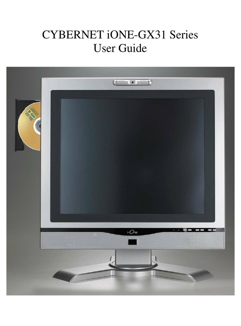
Cybernet iONE-GX31 Series User manual

Cybernet
Cybernet i-One 17 User manual

Cybernet
Cybernet iOne-H19 Series User manual

Cybernet
Cybernet ZPC-GX31 User manual

Cybernet
Cybernet Elite-4i User manual

Cybernet
Cybernet CyberMed H22 User manual

Cybernet
Cybernet C22 SERIES User manual

Cybernet
Cybernet IPC-R2ix User manual