4
6.2 Rear Panel
IR OUT
IR IN
ALL A B C D E F G H
IR OUT
IR IN
CAT5e/6 OUT
IR OUT
IR IN
CAT5e/6 OUT
IR OUT
IR IN
CAT5e/6 OUT
IR OUT
IR IN
CAT5e/6 OUT
IR OUT
IR IN
CAT5e/6 OUT
IR OUT
IR IN
CAT5e/6 OUT
IR OUT
IR IN
CAT5e/6 OUT
IR OUT
IR IN
CAT5e/6 OUT
1
HDMI IN
2
HDMI IN
3
HDMI IN
4
HDMI IN
5
HDMI IN
6
HDMI IN
7
HDMI IN
8
HDMI IN
SERVICE
RS232
MAIN 24V
POE 24V
1
2
3
4
V+
GND
GND GND
V+
CONTROL
2 4
510 1118 9
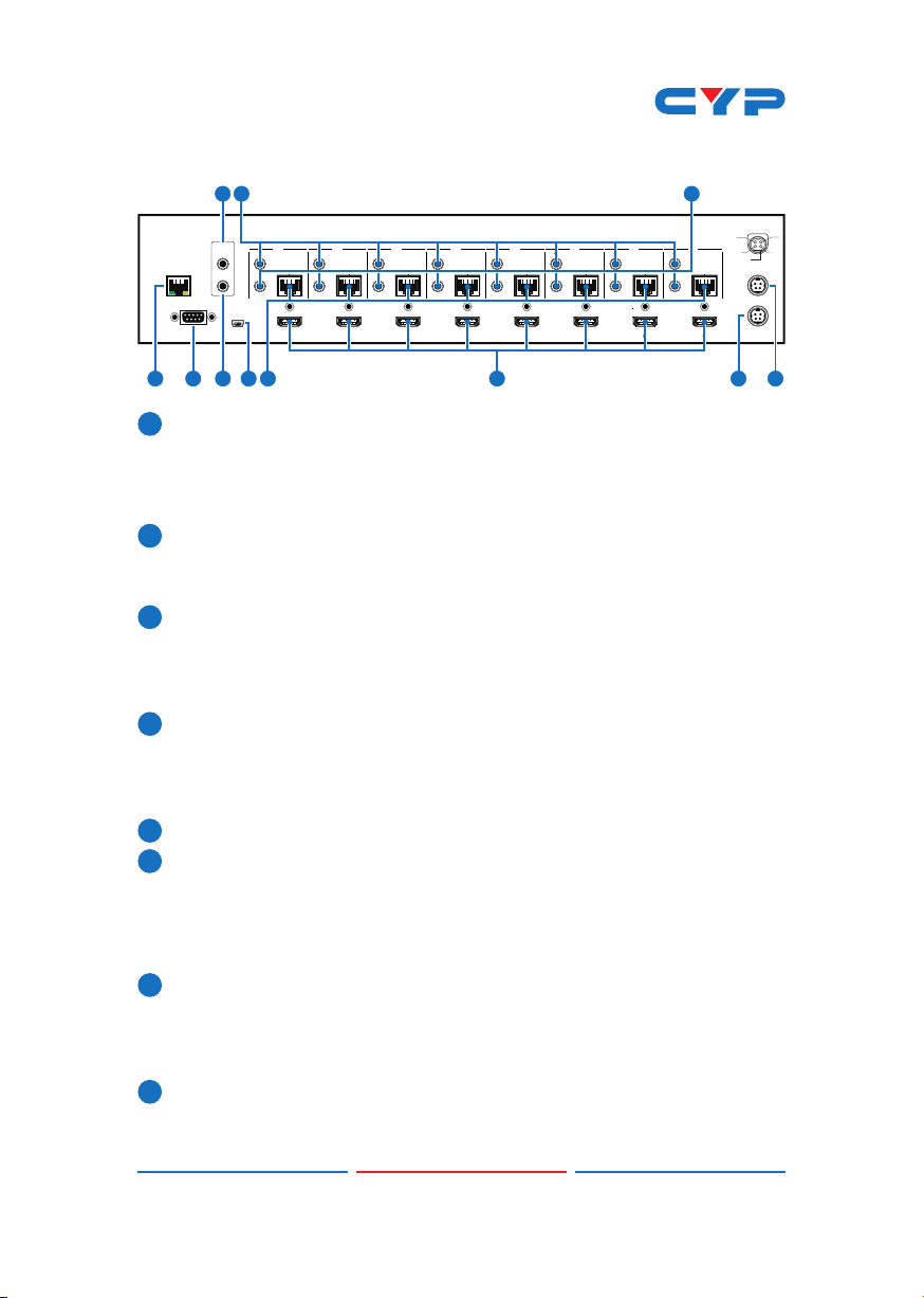
1CONTROL: Connect to an active network for Telnet and Web GUI
control (refer to Sections 6.8 and 6.9).
Warning: Please do not connect this port directly to the PC/Laptop
as the Telnet function will not work.
2RS-232: Connect to a PC or control system with D-Sub 9-pin cable
to control the matrix with RS-232 commands (refer to Sections 6.6
and 6.7.
3ALL IR OUT: Connect an IR Blaster for IR signal transmission to the
source/input location. Place the IR Blaster in direct line-of-sight
of the equipment to be controlled. It will transmit all IR signals
received by any IR extenders connected to the matrix or receivers.
4ALL IR IN: Connect an IR extender for IR signal reception. Ensure
that remote being used is within the direct line-of-sight of the
IR extender. IR signals received will transmitted by all IR blasters
connected to the matrix or receivers.
5SERVICE: Manufacturer use only.
6IR OUT 1~8: Connect to the IR blasters for IR signal transmission.
Place the IR blaster in direct line-of-sight of the equipment to be
controlled. It will transmit the IR signal received from IR extenders
connected to the matrix or receivers according to the selected
input.
7IR IN 1~8: Connect to the IR extenders for IR signal reception. Ensure
that remote being used is within the direct line-of-sight of the IR
extender. The IR signal will be tranmitted to the selected receiver's
IR OUT.
8CAT5e/6/7 OUT 1~8: Connect from these CAT outputs to the CAT
input port of the receiver units with a single CAT5e/6/7 cable for HDMI
Audio/Video and IR/RS-232 control signal transmission.