CYP CH-1529TXPLV User manual

CH-1529TXPLV
4K UHD+HDMI over HDBaseT Transmitter
with HDR & OAR
Operation Manual
Operation Manual


DISCLAIMERS
The information in this manual has been carefully checked and
is believed to be accurate. Cypress Technology assumes no
responsibility for any infringements of patents or other rights of third
parties which may result from its use.
Cypress Technology assumes no responsibility for any inaccuracies
that may be contained in this document. Cypress also makes no
commitment to update or to keep current the information contained
in this document.
Cypress Technology reserves the right to make improvements to this
document and/or product at any time and without notice.
COPYRIGHT NOTICE
No part of this document may be reproduced, transmitted,
transcribed, stored in a retrieval system, or any of its part translated
into any language or computer le, in any form or by any means—
electronic, mechanical, magnetic, optical, chemical, manual, or
otherwise—without express written permission and consent from
Cypress Technology.
© Copyright 2018 by Cypress Technology.
All Rights Reserved.
TRADEMARK ACKNOWLEDGMENTS
All products or service names mentioned in this document may be
trademarks of the companies with which they are associated.

SAFETY PRECAUTIONS
Please read all instructions before attempting to unpack, install or
operate this equipment and before connecting the power supply.
Please keep the following in mind as you unpack and install this
equipment:
• Always follow basic safety precautions to reduce the risk of re,
electrical shock and injury to persons.
• To prevent re or shock hazard, do not expose the unit to rain,
moisture or install this product near water.
• Never spill liquid of any kind on or into this product.
• Never push an object of any kind into this product through any
openings or empty slots in the unit, as you may damage parts
inside the unit.
• Do not attach the power supply cabling to building surfaces.
• Use only the supplied power supply unit (PSU). Do not use the PSU
if it is damaged.
• Do not allow anything to rest on the power cabling or allow any
weight to be placed upon it or any person walk on it.
• To protect the unit from overheating, do not block any vents or
openings in the unit housing that provide ventilation and allow for
sufcient space for air to circulate around the unit.
• Please completely disconnect the power when the unit is not in
use to avoid wasting electricity.
REVISION HISTORY
VERSION NO. DATE SUMMARY OF CHANGE
VS1 21/05/18 Final technical review

CONTENTS
1. Introduction......................................................1
2. Applications.....................................................1
3. Package Contents ..........................................2
4. System Requirements......................................2
5. Features............................................................2
6. Operation Controls and Functions.................3
6.1 Front Panel ................................................. 3
6.2 Rear Panel.................................................. 5
6.3 Right Panel................................................. 6
6.4 IR Cable Pinouts ........................................ 6
6.5 RS-232 Control ........................................... 7
6.6 RS-232 Commands.................................... 7
6.7 EDID Management ................................... 9
6.7.1 EDID Dipswitch Settings ................... 9
6.7.2 EDID Management Tool................ 11
7. Connection Diagram ....................................15
8. Specications ................................................16
8.1 Technical Specications ........................ 16
8.2 Video Specications............................... 17
8.3 Audio Specications............................... 18
8.4 Cable Specications .............................. 19
8.5 HDBaseT Features.................................... 19
9. Acronyms .......................................................20

1
1. INTRODUCTION
This HDMI over single Cat.5e/6/7 Transmitter is a great solution for
extending HD audio and video as well as Ethernet and control via
a single run of Cat.5e/6/7 cable over distances of up to 70 meters.
Multiple data and control interfaces are provided, including IR and
RS-232 connections. This Transmitter complies with the advanced
HDCP 2.2 and HDMI 2.0 standards, as well as supporting the legacy
HDCP 1.x and HDMI 1.x standards. Despite HDBaseT’s 10.Gbps
bandwidth limitation, 4K UHD HDMI video sources, up to and including
4K@60Hz (4:4:4, 8-bit) as well as 10/12-bit sources with HDR, are able
to be processed and extended by the use of AVLC (Adaptive Visually
Lossless Compression) when connected to a compatible AVLC
Receiver.
Beyond video, data, and control this unit also contains useful audio
features. The Optical Audio Return (OAR) feature supports transmitting
optical audio back from a compatible Receiver for local playback.
Rounding out the feature set is robust EDID management as well as
automatic HDBaseT clock stretching and TMDS re-clocking support.
This Transmitter (PSE) can provide 48V PoH (Power over HDBaseT)
to a compatible Receiver (PD), allowing for greater exibility within
different installation scenarios.
2. APPLICATIONS
• 48V PoH from Transmitter (PSE) to Receiver (PD)
• Household entertainment sharing and control
• Lecture room display and control
• Showroom display and control
• Meeting room presentation and control
• Classroom display and control

2
3. PACKAGE CONTENTS
• 1×HDMI over HDBaseT Transmitter with HDR & OAR
• 1×48V/0.83A DC Power Adapter
• 1×Power Cord
• 1×3.5mm to IR Blaster Cable
• 1×3-pin Terminal Block to 9-pin D-sub Adapter Cable
• 1×Rackmount Ears (Set of 2)
• 1×Operation Manual
4. SYSTEM REQUIREMENTS
• HDMI source equipment such as a media player, video game
console or set-top box.
• A compatible HDBaseT Receiver with AVLC and 48V PoH support is
recommended.
• The use of industry standard Cat.6, Cat.6a or Cat.7 cable is highly
recommended.
• The use of “Premium High Speed HDMI” cables is highly
recommended.
5. FEATURES
• HDMI with HDR, 3D & 4K@60Hz support, DVI 1.0 compatible
• HDCP 2.2 and HDCP 1.x compliant
• Supports up to 4K UHD (18Gbps, 4K@50/60Hz 4:4:4, 8-bit) video input
and output
• Supports Deep Color input and output up to 12-bit
• Supports 10-bit and 12-bit HDR (High Dynamic Range) input/output
• Supports CEC bypass
• Simultaneous transmission of uncompressed video, audio and data
over a single Cat.5e/6/7 cable up to 70m/230ft at 1080p60 and
35m/115ft at 4K
• HDBaseT feature support: HD Video and Audio, 48V PoH, and
Control (bidirectional IR/RS-232 pass-through)

3
• Integrated AVLC (Adaptive Visually Lossless Compression) activates
when the bandwidth requirements of the source are beyond
10.2Gbps (340MHz) allowing for sources up to 18Gbps (600MHz) to
be sent to a compatible Receiver with no loss of visual quality
• The AVLC feature allows manual selection between High Quality
Mode (Full bandwidth) and Standard Mode (Lower bandwidth,
useful for longer cable runs with 4K sources)
• Supports the Optical Audio Return (OAR) function to transmit optical
audio from a compatible Receiver to the Transmitter
• Comprehensive EDID management support including 6 pre-dened
EDIDs, 9 user EDIDs and an EDID bypass mode
• PC-based EDID management software allows for the uploading of
customized user EDIDs via USB
• Supports HDMI DDC bus clock stretching for improved compatibility
with certain Blu-ray players
• Performs TMDS re-clocking and signal re-generation for improved
signal integrity
• Ultra-thin wall plate design (16mm thickness) for convenient
installation
• Supports standard 48V PoH from Transmitter (PSE) to Receiver (PD)
(compatible Receivers only)
6. OPERATION CONTROLS AND FUNCTIONS
6.1 Front Panel
CONSOLE/
BYPASS
RX
RS-232SERVICE
OPT. OUT
DC 48V
+
-
POWER
LINK
TX
IR BLASTER 2IR EXTENDER 1
1 2 3 4 5 6 7 8

4
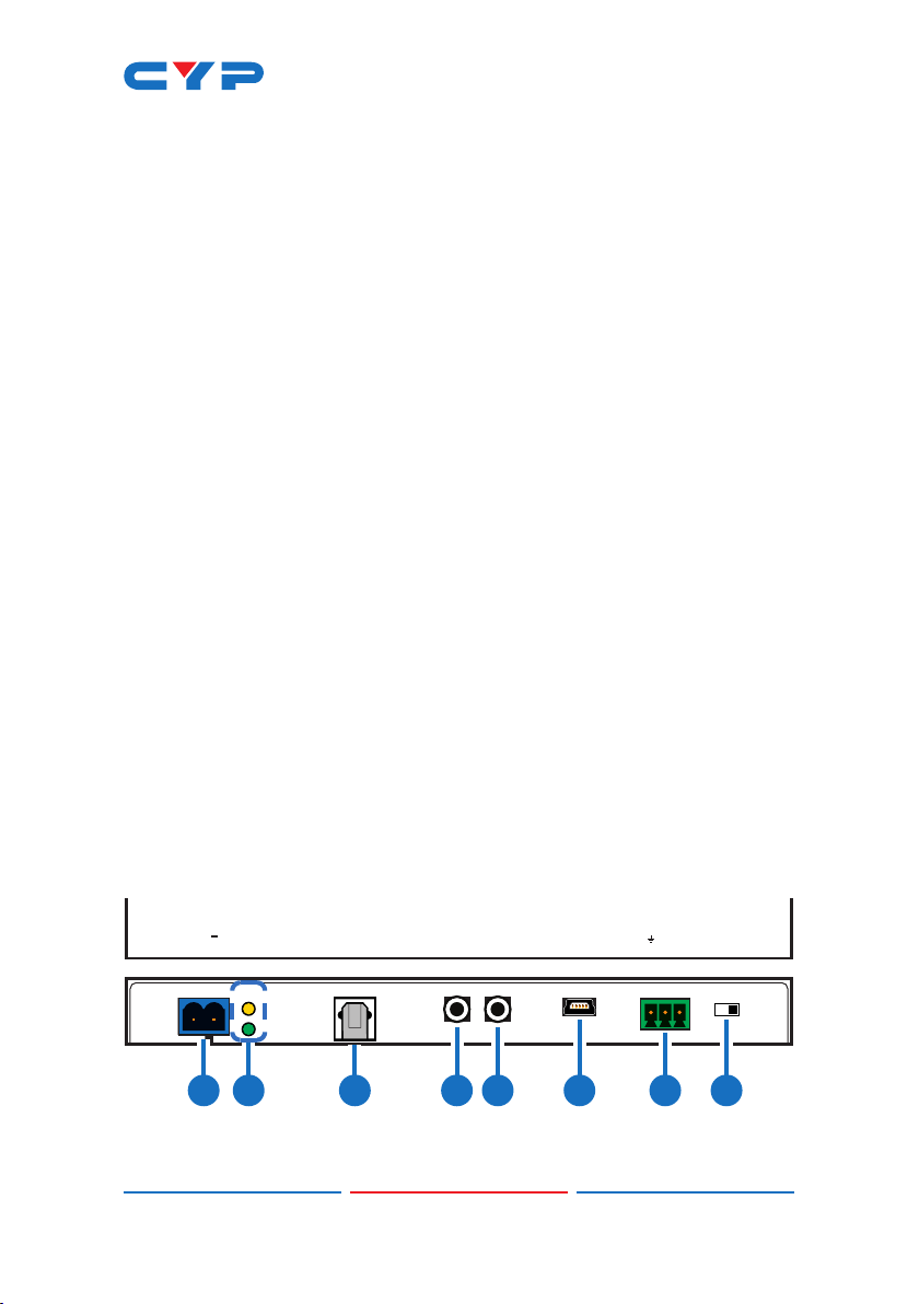
1DC 48V: Plug the 48V DC power adapter into this port and connect
it to an AC wall outlet for power.
Note: Please be sure to follow the polarity labels on the unit and
the adapter’s wires.
2POWER LED: This LED will illuminate to indicate the unit is on and
receiving power.
LINK LED: This LED will illuminate solidly when a live connection with
a compatible Receiver is active.
3OPT. OUT: Connect to powered speakers or an amplier for digital
audio output using an appropriate optical cable. Audio is sourced
from the Optical Audio Return input on a connected compatible
Receiver.
4IR EXTENDER 1: Connect to an IR Extender to extend the IR control
range of devices connected to the other end of the HDBaseT
connection. Ensure that the remote being used is within direct line-
of-sight of the IR Extender.
5IR BLASTER 2: Connect to the provided IR Blaster to transmit IR
signals from the other end of the HDBaseT connection to devices
within direct line-of-sight of the IR Blaster.
6SERVICE: This USB port is reserved for rmware update and user
EDID upload use.
7RS-232: Connect to a PC, laptop or other serial control device with
a 3-pin adapter cable for the extension of RS-232 signals to the
Receiver in "Bypass" mode, or for control this unit when in "Console"
mode.
Note: Depending on the controlled device connected to the
Receiver side, the Tx and Rx pins might need to be reversed.
8CONSOLE/BYPASS: This switch controls the operational mode of the
RS-232 port. When set to “Bypass”, RS-232 signals will be passed to
the connected Receiver. When set to “Console” the RS-232 port
may be used to send commands directly to the Transmitter.
Note: RS-232 bypass requires both the Transmitter and Receiver to
be set to “Bypass” mode.

5
6.2 Rear Panel
CAT5e/6/7 OUTHQ / STD
SWITCH
HQ
STD
HDMI IN
1 2 3 4
1HDMI IN: Connect to HDMI source equipment such as a media
player, game console or set-top box.
2HQ & STD LEDs: These LEDs illuminate to indicate which AVLC mode
will be used when AVLC is required. The lower green LED indicates
that AVLC will use HQ (High Quality) mode. The upper yellow LED
indicates that AVLC will use STD (Standard) mode.
3HQ/STD SWITCH: This switch allows the user to select which
compression mode to use when AVLC is active, High Quality or
Standard.
Note: HQ (High Quality) mode uses the least amount of
compression and provides the highest possible visual quality
(perceptually identical to the original). STD (Standard Quality)
mode applies additional signal reduction methods to lower
the bandwidth requirements of 4K sources further, improving
transmission reliability over longer cable runs at the cost of some
visual delity.
4CAT5e/6/7 OUT: Connect to a compatible HDBaseT Receiver with
a single Cat.5e/6/7 cable for transmission of all data signals. 48V
PoH will also be supplied when connected to a compatible PD
Receiver.
Note: The 48V PoH function is designed for powering compatible
Receiver units only. Non-PoH Receivers will need their own power
supply. Receivers from other brands may not be compatible.

6
6.3 Right Panel
EDID
ON
1234
1
1EDID: The EDID dipswitch block provides a way to select the EDID
to use with the connected source. By using a combination of on
and off settings for the dipswitches, there are a total of 16 possible
EDID selections across 3 different operation modes.
The three modes are “Internal EDID”, “User EDID” and “External
EDID”. There are a total of 6 built-in internal EDIDs and 9 User EDIDs
(which can be modied via USB upload). The “External EDID”
setting will copy the EDID from the sink that is connected to the
Receiver. (See “EDID Management” for more details.)
6.4 IR Cable Pinouts
3
1
2
Infrared
Power
Ground
IR Extender
3
1
2
IR Blaster Power
Infrared
NC

7
6.5 RS-232 Control
Terminal Block Controlling PC Serial Port Settings
Pin Denition Pin Denition Baud Rate 19200
1GND 1Data Bits 8
2Rx 2Rx Parity Bit None
3Tx 3Tx Stop Bits 1
4Flow Control None
5GND
6
7
8
9
6.6 RS-232 Commands
COMMAND
Description and Parameters
HELP
Show the full command list.
?
Show the full command list.
GET FW VER
Show the unit’s current rmware version.
GET MODEL NAME
Show the unit’s model name.
GET MODEL TYPE
Show the unit’s model type.
GET POWER
Show the power state of the unit.

8
COMMAND
Description and Parameters
SET SYSTEM REBOOT
Reboot the unit.
GET IN 1 SYNC STATUS
Show the current input sync state.
GET OUT A SYNC STATUS
Show the current output sync state.
GET IN 1 EDID
Show the input’s current EDID source.
GET IN EDID LIST
List all available EDID selections.
SET TRANSCEIVER COMPRESS RATE N1
Set the AVLC compression mode to use.
Available values for N1:
1 [High quality]
2 [Standard quality]
GET TRANSCEIVER COMPRESS RATE
Show the current AVLC compression mode.
Note: Commands will not be executed unless followed by a carriage
return. Commands are not case-sensitive.

9
6.7 EDID Management
6.7.1 EDID Dipswitch Settings
The EDID dipswitch block provides a way to select the EDID to use with
the connected source. By using a combination of on and off settings
for the dipswitches, there are a total of 16 possible EDID selections
across 3 different operation modes.
1 = Dipswitch in “on” (down) position
0 = Dipswitch in “off” (up) position
ON
1234
= 0
= 1
EDID Mode Number
EDID
Number
Dipswitch
Position
Internal EDID 1 1 1111
2 2 1110
3 3 1101
4 4 1100
5 5 1011
6 6 1010
User EDID 1 7 1001
2 8 1000
3 9 0111
4 10 0110
5 11 0101
6 12 0100
7 13 0011
8 14 0010
9 15 0001
Native EDID 16 0000

10
Detailed EDID information:
• Internal EDID (1–6)
There are a total of 6 built-in internal EDID slots covering many
standard display congurations. These EDIDs can’t be modied. They
are dened as follows:
EDID Video Content Audio Content
FHD/2 channel 1080p@60Hz, 8-bit LPCM 2.0 (148MHz)
FHD/Multi-channel 1080p@60Hz, 8-bit LPCM 7.1 + Bitstream
(148MHz)
UHD/2 channel 3840×2160p@30Hz,
8-bit
LPCM 2.0 (297MHz)
UHD/Multi-channel 3840×2160p@30Hz,
8-bit
LPCM 7.1 + Bitstream
(297MHz)
UHD+/2 channel 3840×2160p@60Hz,
up to 12-bit
LPCM 2.0 (594MHz)
UHD+/Multi-channel 3840×2160p@60Hz,
up to 12-bit
LPCM 7.1 + Bitstream
(594MHz)
• User EDID (1–9)
There are a total of 9 User EDID slots which can be modied via USB
upload. By default, these slots all contain the same standard EDID:
EDID Video Content Audio Content
FHD/2 channel 1080p@60Hz, 8-bit LPCM 2.0 (148MHz)
• Native (External) EDID
The Native EDID setting will copy the EDID from the sink that is
connected to the Receiver.

11
6.7.2 EDID Management Tool
This unit uses an EDID Management application which allows the user
to copy the EDID from an attached display, edit an existing EDID le
stored on the PC or create a basic EDID from scratch. The EDID can
then be uploaded to the unit for use.
Please obtain the EDID Management software from your authorized
dealer and save it in a directory where you can easily nd it.
Before connecting the unit to your PC, please install the appropriate
Virtual COM Port Driver depending on your Windows version. Next,
install the EDID Management software.
After the installation has successfully completed an icon for it will
appear on the windows desktop. Launch the software by double-
clicking on the icon and the EDID Management device detection
window will open up on your screen.
After launching the software, power the unit on and then connect it
to the PC/laptop using a Mini-USB to USB cable. Click on the “Search”
button and any detected units will be displayed in the list.
Clicking on a detected unit will open the EDID Commander window.

12
A. EDID Controller Tab
• Mode Select: Under the EDID Controller tab you will see the currently
selected EDID slot (based on dipswitch position). The software can’t
change this selection, only monitor it.
• Save/Upload/Analysis: EDIDs may be saved, uploaded or analyzed:
-Save: Any EDID from the unit or a connected HDMI display can be
saved to your PC as a *.bin le by selecting the EDID source from
the drop down menu and then clicking the “Save” icon.
- Upload: Previously saved EDID les (*.bin format) can be re-
uploaded into any of the “User” EDID slots by selecting the
User EDID to replace from the dropdown and then clicking the
“Upload” icon. Before accepting the upload, the software will
check and verify that the EDID’s header and checksum values
are acceptable.
- Analysis: To analyze any EDID stored within the unit, select the
EDID to view from the dropdown and click on the “Analysis”
icon. From the Analyzer window it is possible to open the currently
analyzed EDID in the EDID Creator by clicking the “Edit” button.

13
B. EDID Creator Tab
• Select: Click on the EDID Creator tab to begin designing a new EDID
from scratch (select the “New” icon), to modify an existing EDID
stored on the PC as a *.bin le (select the “Load” icon) or to edit
an EDID copied from the unit via the EDID Analyzer’s edit option.
- Selecting “New” will automatically populate the various EDID
elds with basic information that can be easily edited to match
the user’s preferences.
- Clicking on the “Load” icon will open a le load window and
after the *.bin le has been selected and loaded the EDID elds
will be populated with the information from that le. The same will
happen when the EDID is copied from the EDID Analyzer window.

14
• Edit: The following tabs provide access to a wide range of EDID
information which can be edited:
- Descriptor: This tab allows for the editing of various description
and information elds within the EDID le such as Manufacturer
Name, Monitor Name, etc.
- PC Timing & SD/HD/UHD: These tabs allow for the selection of the
resolutions and refresh rates that the EDID will report as supported.
- Audio1 & Audio2: These tabs allow for the selection of which
audio formats, audio frequencies, channels and speaker locations
are supported.
- Color Space: This tab allows for the selection of which color
formats and bit depths are supported, including BT.2020 and HDR
support options.
- Others: This tab contains options for supporting 3D and dening
the CEC Address.
Once the user is nished editing or creating an EDID it can be saved
to a *.bin le locally or uploaded directly to the unit using the “Save”
and “Upload” icons respectively.
C. System Tab
• Conguration & Firmware: Select the System tab to edit the unit’s
description (select the “Rename” icon), to reset the unit to
factory defaults (select the “Reset” icon) and to view the unit’s
current hardware and rmware version information.

15
7. CONNECTION DIAGRAM
TX
RX
EDID
CAT5e/6/7OUTHQ / STD
SWITCH
HQ
STD
HDMI IN
CONSOLE/
BYPASS
RX
RS-232SERVICEOPT. OUTDC 48V
+
-
POWER
LINK
TX
UHD+ HDMI OVER HDBaseT TRANSMITTER
WITH HDR / OAR
PoH-PSE
AVLC
35M
IR BLASTER 2IR EXTENDER 1
UHD+ HDMI OVER HDBaseT RECEIVER
WITH HDR / OAR
CAT5e/6/7IN HQ
STD
HDMI OUT
CONSOLE/
BYPASS
RX
RS-232SERVICE
OPT. IN
TX
LINK
POWER
PoH-PD
AVLC
35M
IR BLASTER 1IR EXTENDER 2
7m3m 3m
60°
1.5m
60°
1.5m
60°
7m3m 3m
60°
Game Console
UHDTV (w/ Optical
Audio Output)
RS-232 Controlled
Device
Power Supply
Router
RS-232
RS-232
USB
RS-232 Equipped
PC/Laptop
HDMI
Input
HDMI
Output
Cat.5e/6/7
Cable
Optical Audio
Retun (OAR)
IR In & Out
IR In & Out
Optical Audio
Return (OAR)
AV Receiver
Table of contents
Other CYP Transmitter manuals

CYP
CYP CH-103TX User manual

CYP
CYP PU-507TX-1H User manual

CYP
CYP PUV-1830TX-AVLC User manual

CYP
CYP AVIP-P5104T-B1C User manual

CYP
CYP PU-1109 User manual

CYP
CYP CH-306TXA & RXA User manual

CYP
CYP CH-1605TXV User manual

CYP
CYP PUV-1710LTX-AVLC User manual

CYP
CYP PUV-1620S-TX User manual

CYP
CYP CH-506RXWP User manual