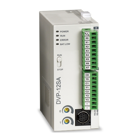
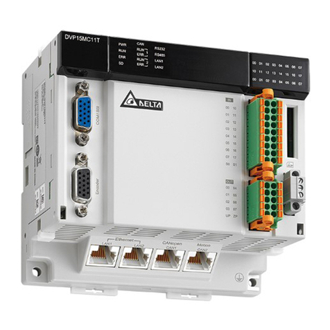
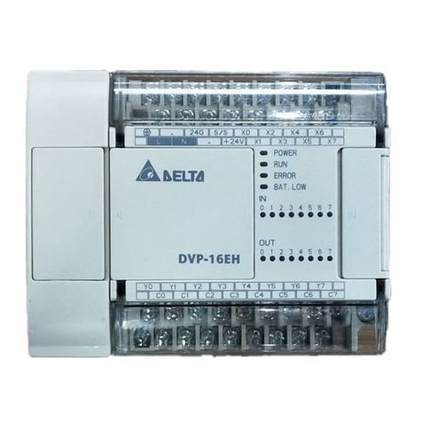
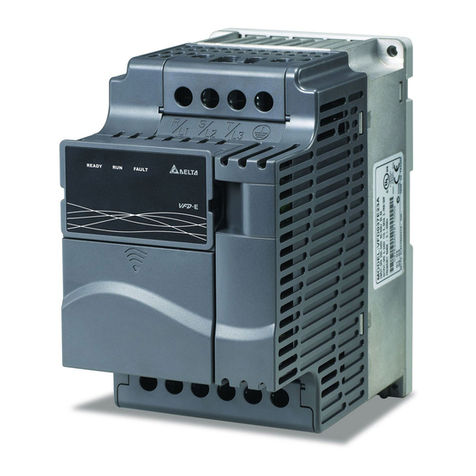
Delta DVP-PM Series Instructions for use


DVP-PM APPLICATION MANUAL
Table of Contents
Chapter 1: Program Structure of DVP-PM
1.1 O100 Main Program............................................................................1-1
1.2 Structure of OX Motion Subroutine.......................................................1-3
1.3 Structure of Pn Subroutine ..................................................................1-5
1.4 Structure of O100, OX and Pn Program Design ....................................1-7
1.4.1 The Program Structure …………………………………………………………………1-7
Chapter 2: Hardware Specifications and Wiring
2.1 Hardware Specifications......................................................................2-1
2.1.1 Electrical Specifications ............................................................................. 2-1
2.1.2 I/O Point Specifications.............................................................................. 2-1
2.1.3 Dimension ................................................................................................. 2-6
2.2 Installation and Wiring.........................................................................2-8
2.2.1 Wiring ....................................................................................................... 2-8
2.2.2 Power Input Wiring .................................................................................... 2-9
2.2.3 Safety Wiring............................................................................................. 2-9
2.2.4 I/O Point Wiring ......................................................................................... 2-10
2.2.5 Wiring with Drives...................................................................................... 2-18
2.3 Communication Ports..........................................................................2-28
2.3.1 COM1 (RS-232)......................................................................................... 2-28
2.3.2 COM2 (RS-485)......................................................................................... 2-29
2.3.3 COM2 (RS-232/RS-485)............................................................................. 2-29
Chapter 3: Functions of Devices in DVP-PM
3.1 Device in DVP-PM ..............................................................................3-1
3.2 Values, Constants [K]/[H], Floating Points [F] .......................................3-4
3.3 Numbering and Functions of External Input/Output Contacts [X]/[Y]....... 3-6
3.4 Numbering and Functions of Auxiliary Relays [M] .................................3-7
3.5 Numbering and Functions of Step Relays [S]........................................ 3-8
3.6 Numbering and Functions of Timers [T]................................................3-8

3.7 Numbering and Functions of Counters [C]............................................3-9
3.8 Numbering and Functions of Registers [D]] ..........................................3-16
3.8.1 Data Register [D]....................................................................................... 3-16
3.8.2 Index Registers [V], [Z] .............................................................................. 3-16
3.9 Pointer [N], Pointer [Pn].......................................................................3-17
3.10 Special Auxiliary Relays [M], Special Data Register [D].......................... 3-18
3.11 Functions of Special Auxiliary Relays and Special Registers...................3-35
3.12 Special Registers for Manual Motion Settings........................................3-57
3.12.1 Functions of Special Registers for Manual Mode Settings .......................... 3-59
3.12.2 Manual Modes ......................................................................................... 3-77
3.12.3 Position & Speed Control Registers for Manual Modes............................... 3-78
Chapter 4: Basic Instructions
4.1 Basic Instructions ...............................................................................4-1
4.2 Explanations on Basic Instructions ......................................................4-3
Chapter 5: Categories and Use of Basic Application Instructions
5.1 List of Instructions ..............................................................................5-1
5.2 Instruction Composition.......................................................................5-5
5.3 Numeric Values for Data Processing....................................................5-7
5.4 Index Register V, Z .............................................................................5-10
5.5 Instruction Index.................................................................................5-11
5.6 Application Instructions.......................................................................5-15
●(API 00 ~ 09) Loop Control................................................................ 5-15
●(API 10 ~ 19) Transmission Comparison............................................. 5-23
●(API 20 ~ 29) Four Arithmetic Operations ........................................... 5-36
●(API 30 ~ 39) Rotation and Displacement........................................... 5-48
●(API 40 ~ 49) Data Processing........................................................... 5-59
●(API 50) High Speed Processing................................................. 5-72
●(API 61 ~ 69) Handy Instructions ....................................................... 5-74
●(API 78 ~ 87) I/O............................................................................... 5-80
●(API 100 ~ 109) Communications........................................................... 5-85
●(API 110 ~ 175) Floating Point Operation ............................................... 5-94
●(API 215 ~ 223) Contact Type Logic Operation ....................................... 5-126
●(API 224 ~ 246) Contact Type Comparison............................................. 5-129

●(API 147 ~ 260) Other Instructions......................................................... 5-132
Chapter 6: Motion Instructions and G-Code Instructions
6.1 List of Motion Instructions and G-Code Instructions..............................6-1
6.2 Composition of Motion Instructions and G-Code Instructions................. 6-3
6.2.1 Motion Instructions..........................................................................6-3
6.2.2 G-Code Instructions ……………………………………………………………….. 6-4
6.3 Motion Instructions............................................................................6-6
●(MON 00 ~ 19) Motion Instructions............................................................ 6-6
6.4 O Pointer / M Pointer.................................................................................... 6-40
6.5 G-Code Instructions............................................................................6-44
●(G0 ~ 4, 90 ~ 91) G-Code Instructions ...................................................... 6-44
Chapter 7: Use DVP-PM As Slave
7.1 Access between DVP-EH2, DVP-PM (as Master) and DVP-PM (as Slave) 7-1
7.1.1 The Structure............................................................................................. 7-1
7.1.2 Example of Master-Slave Data Exchange.................................................... 7-2
Chapter 8: Application Examples
8.1 Draw the Trajectories by Using Motion Instructions and G-Codes........... 8-1
8.1.1 Trajectory .................................................................................................. 8-1
8.1.2 Design Procedure ...................................................................................... 8-3
8.2 Applying Application Examples in PMSoft....................................................... 8-7
8.2.1 Program Structure...................................................................................... 8-7
8.2.2 Design Example Program........................................................................... 8-8
8.3 Planning Variable Speed Operation................................................................ 8-10
8.3.1 Program structure ...................................................................................... 8-10
8.3.2 Design Example Program ......................................................................... 8-11
8.4 Connect DVP-PM (Master) with DVP01PU-H2 (Slave) for 3rd Axis Control........ 8-14
Chapter 9: Electrical Cam
9.1 Introduction to Electrical CAM (E-CAM).................................................... 9-1
9.2 E-CAM Application..................................................................................... 9-2
9.2.1 Initial Settings............................................................................................ 9-2
9.2.2 Obtain Master Position............................................................................... 9-6

9.2.3 Start / Stop E-CAM..................................................................................... 9-9
9.3 Explanations on Special Flags and Registers........................................... 9-16
9.4 Set up E-CAM Data ................................................................................... 9-21
9.4.1 Use PMsoft CAM Chart to Set up E-CAM Data............................................. 9-21
9.4.2 Use DTO / DFROM Instructions to Set up E-CAM Data ................................ 9-27
9.5 Multi-axis E-CAM....................................................................................... 9-53
9.6 Field Applications of E-CAM...................................................................... 9-57
9.6.1 E-CAM Application on Winding Machine...................................................... 9-57
9.6.2 E-CAM Application on Rotary Cut and Flying Saw Devices........................... 9-64
Chapter 10: Encrypting User Program
10.1 Password Setting..................................................................................... 10-1
10.1.1 System Information .................................................................................. 10-1
10.1.2 Downloading Program .............................................................................. 10-3
10.1.3 Uploading Program................................................................................... 10-6
Chapter 11: G-code Application
11.1 DVP-PM00M Program Download with PEP setting................................. 11-1
11.2 DVP-PM00M G-code Download Methods................................................ 11-2
11.2.1 PMGDL Software...................................................................................... 11-2
11.2.2 Download by B Type HMI.......................................................................... 11-8
11.2.3 Download by HMI other than B type through D registers............................. 11-13
11.3 G-code Application in Dispensers ........................................................... 11-17
11.3.1 Operation steps........................................................................................ 11-17
11.3.2 Storage of G/M code................................................................................. 11-22
Chapter 12: POU Editing Mode
12.1 POU Ladder Editing Environment ........................................................... 12-1
12.1.1 Function of Symbols................................................................................. 12-2
12.1.2 Editing Symbol Tables .............................................................................. 12-4
12.1.3 Create POU Function Block ...................................................................... 12-15
12.1.4 Create POU Folders................................................................................. 12-18
12.1.5 Export POU.............................................................................................. 12-23
12.1.6 Import POU.............................................................................................. 12-30
12.1.7 Symbols Allocation................................................................................... 12-33

12.1.8 Ladder Find ............................................................................................. 12-36
12.1.9 Ladder Replace ....................................................................................... 12-40
12.2 Edit POU Ladder Diagram....................................................................... 12-41
12.2.1 Replace Devices with Symbols.................................................................. 12-41
12.2.2 Applying POU Function Blocks.................................................................. 12-43
12.3 Monitor POU program.............................................................................. 12-50
12.4 Hint Function on Symbols and Function Blocks...................................... 12-54
Chapter 13: CANopen Communication Card
13.1 Introduction to DVP-FPMC: CANopen Communication Card ................. 13-1
13.2 Specifications........................................................................................... 13-1
13.3 Product Profile & Installation................................................................... 13-2
13.4 Parameters for Control Register (CR)..................................................... 13-3
13.5 How to Set Up ASDA-A2 Servo Drive ..................................................... 13-5
13.6 DVP-FPMC Mode Settings ...................................................................... 13-20
13.7 DVP-FPMC Ethernet Applications........................................................... 13-24
13.7.1 Communication between DVP-FPMC and HMI ........................................... 13-24
13.7.2 Communication between DVP-FPMC and PMSoft ...................................... 13-27
13.8 LED Indicator & Troubleshooting........................................................13-30
Chapter 14: High Speed Compare and Capture
14.1 High Speed Compare and Capture Function........................................... 14-1
14.2 High Speed Compare Function................................................................ 14-4
14.3 Capture Function ..................................................................................... 14-8
Chapter 15: Appendix
15.1 Appendix A: Error Codes ...................................................................14-1
15.2 Appendix B: Manual Revision History.................................................14-2
15.3 Appendix C: Function Comparison Table of DVP-PM Models..................... 14-2

1Program Structure of DVP-PM
DVP-PM Application Manual 1-1
Delta’s DVP-PM series MPU is a high-speed positioning and multi-functional programmable logic controller with
2-axis linear/arc interpolation, featuring functions as basic instructions, application instruction (API), motion
instruction (MON) and G-code instructions, making the editing and compiling of program more diverse.
This chapter will introduce the program structure of DVP-PM series MPU. DVP-PM combines the sequential control
and 2-axis interpolation positioning control; therefore, the program is in three types: O100 main program, OX motion
subroutine and Pn subroutine, which will be illustrated in this chapter.
The basic instructions, application instructions (API), motion instructions (MON) and G-Code instructions will be
given in Chapter 4 ~ 6.
Here we provide a specification comparison table of different model PLCs for your reference:
PLC Models
Specifications DVP-10PM DVP-20PM
High speed output 1000kHz 4 sets 500kHz 3 sets
PWM Accuracy 0.3%@200KHz
Hardware high speed counter 6 sets (differentialx2,
open collector x4)
2 sets
Program capacity 64K Steps 64K Steps
Execution speed LD: 0.14us
MOV: 2us
DMUL: 7.6us
DEMUL: 6.1us
1.1 O100 Main Program
O100 main program is the PLC sequential control program for DVP-PM series MPU. The O100 main program
section only supports basic instructions and application instructions. Besides processing I/O signals and calling Pn
subroutine, basic instructions and application instructions also control 100 OX motion subroutines which enable
OX0 ~ OX99. Therefore, O100 main program establishes the main control program, and the main control program
sets up and activates motion subroutines. This is the control structure of the operation of DVP-PM. See below the
operation procedure and features of O100 main program.
1. There are two ways to activate O100 main program
zWhen DVP-PM is powered, and the AUTO/MANU switch goes from MANU to AUTO, M1072 will be
ON automatically, and O100 main program will be in RUN status.
zWhen DVP-PM is powered, you can set M1072 to be ON or O100 main program to be in RUN status
by communication.

1Program Structure of DVP-PM
DVP-PM Application Manual
1-2
Auto/Manu
Communication M1072 O100
Run
2. O100 main program operates in cyclic scans. When O100 main program is enabled, the scan will start at
the start flag of O100. When the scan reaches M102 (main program ends instruction), it will return to the
start flag of O100 and repeat the scan, as shown in the figure below:
O100
M102
.
.
.
Pointer indicating start of mainprogram
Cyclic scan
Sequential control program area
M-code indicating endof main program
3. There are three ways to stop the operation of O100 main program:
zWhen DVP-PM is powered, and the AUTO/MANU switch goes from AUTO to MANU, M1072 will be
OFF automatically, and O100 main program will be in STOP status. The operation of OX and Pn
subroutines will stop at this moment.
zWhen DVP-PM is powered, you can set M1072 to be OFF or O100 main program to be in STOP
status by communication. The operation of OX and Pn subroutines will stop immediately.
zWhen errors occur during compiling or operation of the program, O100 main program will stop
automatically. See Chapter 14 Index for the table of the error codes and their causes.
4. O100 main program supports basic instructions and application instructions; therefore, you can design the
program according to your actual needs. Besides, you can further activate OX0 ~ OX99 motion subroutines
by setting up the parameters in motion subroutines and the activation No. in the motion subroutines.
zO100 main program does not support motion instructions and G-Code instructions. Please design
motion instructions and G-Code instructions in OX0 ~ OX99 subroutines. See 1.2 for more details.
zO100 main program is able to call Pn subroutines. See 1.3 for more details.
5. The above explanations are sorted in the table below:
O100 main program Explanation
Start of O100 O100, pointer indicates the start of O100 main program (*It will be inserted by PMSoft when
compiling to IL instructions, therefore you don’t have to add it into ladder diagram.)
End of O100 M102, instruction indicates the end of O100 main program (*It will be inserted by PMSoft
when compiling to IL instructions, therefore you don’t have to add it into ladder diagram.)
Activation 1. MANU →AUTO by MANU/AUTO switch ON DVP-PM
2. M1072 OFF →ON by communication
Execution Operated in cyclic scans
Instruction supported Basic instructions and application instructions
Quantity Only one O100 program is allowed in the program

1Program Structure of DVP-PM
DVP-PM Application Manual 1-3
Features & functions
1. Performs sequential control of PLC
2. Able to activate OX0 ~ OX99 motion subroutines and call Pn subroutines
3. Can be placed in front of or after OX0 ~ OX99 motion subroutines and Pn subroutines.
6. Manual Motion Mode in O100 Main Program
In O100 main program, you can use special registers for designing Manual Motion Mode. (Please see 3.12
for details of how to set up).
1.2 Structure of OX Motion Subroutine
OX0 ~ OX99 motion subroutines are motion control programs for controlling the motions ON X/Y/Z axes in
DVP-PM. The OX0 ~ OX99 motion subroutines support basic instructions, application instructions, motion
instructions and G-Code instructions. Also OX subroutines are able to call Pn subroutines. OX0 ~ OX99 are
instructions provided specially for controlling the moving path ON X/Y/Z axes. See below the operation procedure
and features of OX motion subroutines.
1. How to activate OX0 ~ OX99 motion subroutines:
zWhen O100 main program is in RUN status, you can set up the execution No. of OX00~OX99
(D1868: H8000 ~ H8063) in O100 main program. After number of OX subroutine is specified, set
M1074 (Enabling OX subroutines) as ON or set b12 of D1846 as 1 to enable OX motion subroutine.
zBefore enabling OX subroutine, make sure there are no other motion subroutines in operation.
OXn (No of OX)
O100 RUN
M1074= ON
or D1846b12 =ON OXn
Run
2. OX subroutine executes once when it is activated. When O100 main program activates OX subroutine,
the execution will start from the start flag of OX motion subroutine and end at M2 (end of OX
subroutine) as shown in the figure below:

1Program Structure of DVP-PM
DVP-PM Application Manual
1-4
MOV
.
.
.
.
.
.
.
.
.
H800A D1868
OUT M1074
X0
X0 = ON
Set No. of OX as O 10. b15=1
enables OX subroutine.
X
Set M1074 = ON or D1846_b12 = 1 to run O 10 motion
subroutine X
Cyclicscan
Executeonce
O100Maincontrolprogram
section
OX10Motionsubrouting
section
MOVP K100 D1836
MOVP K100 D1837
.
.
.
MOV H1000 D1846
Or
When X0 = On, OX10 motion subroutine will execute once and stop when the execution reaches M2. If you
need to execute it again, activate X0 again and OX10 subroutine will be executed again.
3. There are four ways to stop OX motion subroutine:
zWhen DVP-PM is powered, and the AUTO/MANU switch goes from AUTO to MANU, M1072 will be
OFF automatically. O100 main program will be in STOP status. The operation of OX motion
subroutines will stop at this moment.
zYou can also stop OX subroutine by controlling the input signals of the external terminal (STOP0).
zWhen DVP-PM is powered, you can also stop OX subroutine through communication by setting
M1074 to be OFF or D1846 as 0.
zWhen errors occur during compiling or operation of the program, OX subroutines will stop
automatically. See Chapter 11 Index for the table of the error codes and their causes.
4. OX motion subroutines support basic instructions, application instructions (API), motion instructions (MON)
and G-Code instructions. Therefore, you can design your own motion program by using these instructions
and setting up X-Y-Z axis parameters for your desired X-Y-Z motion control.
yThe instructions mentioned above shall be designed in OX0 ~ OX99 motion subroutines.
yOX motion subroutine is able to call Pn subroutines. See 1.3 for more details.
5. The above explanations are sorted in the table below:
OX motion subroutine Explanation
Start of OX OXn, pointer indicates the start of OX subroutine. OX0 ~ OX99, 100 motion subroutines

1Program Structure of DVP-PM
DVP-PM Application Manual 1-5
(*It will be inserted by PMSoft when compiling to IL instructions, therefore you don’t have
to add it into ladder diagram.)
End of OX M2, instruction indicates the end of OX subroutine (*It will be inserted by PMSoft when
compiling to IL instructions, therefore you don’t have to add it into ladder diagram.)
Activation
1. When O100 main program is in RUN status, set M1074 = ON or D1846_b12 = 1 to
enable OX motion subroutine by PMSoft.
2. When O100 main program is in RUN status, set M1074 = ON or D1846_b12 = 1 to
enable OX motion subroutine through communication.
3. OX subroutine can be stopped by input signals at external control terminal (STOP0).
Note: When you need to enable OX motion subroutine, make sure there are no other
motion subroutines in operation.
Execution Execute once whenever the subroutine is enabled. Re-enable it for the re-execution.
Instruction supported
Basic instructions, application instructions (API), motion instructions (MON), and G-Code
instructions.
Note: Avoid pulse-type instruction when using basic instructions and application
instructions.
Quantity 100 OX motion subroutines are available. To activate more OX subroutines, please set
up the number of OX (OXn) in D1868 and set M1074 = ON or D1846_b12 = 1 again.
Features & functions
1. Motion subroutine especially for motion control. (Can be activated only by O100)
2. Offers the third axis (Z) control. See 6.4 G00 and G01 instructions for more details.
3. Can be enabled / disabled by controlling the external terminals, program design and
communication.
4. Able to call Pn subroutine.
5. Can be placed in front of or after O100 main program and Pn subroutines.
1.3 Structure of Pn Subroutine
Pn subroutine is a general-purpose subroutine which can be called in O100 main program and OX motion
subroutines. When Pn subroutine is called in O100 main program, the Pn subroutine area supports basic
instructions and application instructions. When Pn subroutines is called in OX0 ~ OX99 motion subroutines, the Pn
subroutine area supports basic instructions, application instructions (API), motion instructions (MON) and G-Code
instructions.
1. How to enable Pn subroutine:
zCall Pn subroutine in O100 main program.
zCall Pn subroutine in OX motion subroutine.
2. No matter Pn subroutine is called in O100 or OX, the execution will jump to Pn subroutine to execute the Pn
subroutine once. When SRET (Pn subroutine ends instruction) is reached, the execution will return to the
row under CALL Pn instruction and proceed with the remaining program as below.

1Program Structure of DVP-PM
DVP-PM Application Manual
1-6
MOV
CALL
.
.
.
.
.
.
H800A D1868
OUT M1074
X0
P0
P2
CALL
b
a
M1000
M1000
Call P0 subroutine
Set OX as O 10X
When X0 = ON, O 10 motion subroutine
will be enabled. Path a will be true.
X
Call P2 subroutine
O100 and O 10
programbifurcationpoint
X
Cyclicscan
Executeonce
Executeonce
Executeonce
Executeonce
O100Maincontrolprogram
section
OX10Motionsubroutine
section
P2Subroutine
section
P0Subroutine
section
MOVP K100 D1836
ABST
DRV
X -20000
Y20000
MOVP K100 D1837
.
.
.
.
.
.
.
.
.
zP0 subroutine section called by O100 supports only basic instructions and application instructions.
However, P2 subroutine section called by OX subroutine supports basic instructions, application
instructions (API), motion instructions (MON) and G-Code instructions.
3. There are three ways to stop Pn subroutine:
zWhen DVP-PM is powered, and the AUTO/MANU switch goes from AUTO to MANU, M1072 will be
OFF automatically, and O100 main program will be in STOP status. The operation of OX and Pn
subroutines will also stop at this moment.
zWhen DVP-PM is powered, you can also stop OX subroutine by setting M1074 to be OFF or D1846
as 0 through communication, so as to stop the Pn subroutine called by OX subroutine.
zWhen errors occur during compiling or operation of the program, Pn subroutines will stop
automatically. See Chapter 14 Index for the table of the error codes and their causes.
4. The above explanations are sorted in the table below:

1Program Structure of DVP-PM
DVP-PM Application Manual 1-7
Pn subroutine Explanation
Start of the program Pn, start flag of Pn subroutine (P0 ~ P255) (*It will be inserted by PMSoft when
compiling to IL instructions, therefore you don’t have to add it into ladder diagram.)
End of the program SRET, instruction indicating the end of Pn subroutine (*It will be inserted by PMSoft
when compiling to IL instructions, therefore you don’t have to add it into ladder diagram.)
Activation 1. Call Pn subroutine in O100 main program.
2. Call Pn subroutine in OX motion subroutine.
Execution Execute once whenever the subroutine is enabled. Re-enable it for the re-execution.
Instructions supported
1. When called in O100: supports basic instructions and application instructions
2. When called in OX: supports basic instructions, application instructions (API), motion
instructions (MON) and G-Code instructions.
Note: When you need to call Pn in OX and use basic instructions and application
instructions, please avoid pulse-type instructions.
Quantity 256 Pn subroutines are available
Features & functions 1. A general-purpose subroutine
2. Can be called in O100 main program and OX motion subroutine
3. Can be placed in front of or after O100 main program and OX subroutines.
1.4 Program Design Structure of O100, OX and Pn
O100 main program, OX motion subroutine and Pn subroutine are introduced in 1.1 ~ 1.3. In this section, we will
further illustrate the program structure mixed with the 3 types of programs.
1.4.1 The Program Structure
Assume we would like to design an O100 main program, an OX0 motion subroutine, an OX3 motion subroutine, a P1
subroutine and a P2 subroutine (5 program sections) as the following sequential control process:
O100 main program
M102
.
.
.
.
.
.
.
.
.
.
.
.
.
Call OX0
Call P2
OX0 motion subroutine
Call P1
.
.
.
.
.
.
M2
P2 subroutine
Call OX3
.
.
.
.
.
.
SRET
OX3 motion subroutine
.
.
.
M2
P1 subroutine
.
.
.
SRET
To explain the example in an easier way, the program design will be given in section (1) ~ (5), as shown below:

1Program Structure of DVP-PM
DVP-PM Application Manual
1-8
CALL
.
.
.
.
.
.
.
.
.
.
.
P2
P1
CALL
(1)
(3)
(2)
(5)
MOV H8000 D1868
SET M1074
.
.
.
.
.
BRET
.
.
.(4)
MOV H8003 D1868
SET M1074
.
.
M1000
M1000
Call P1 subroutine
OX0Motionsubroutine
section
Set OX as O 0X
Enable O 0 motion subroutineX
Call P2 subroutine
O100Maincontrolprogram
section
P1Subroutine
section
OX3Motion
subroutine
section
Set OX as O 3X
Enable O 3 motion subroutineX
P2Subroutine
section
DMOV K0 D1848
.
.
M1000
M1000
BRET
.
.

1Program Structure of DVP-PM
DVP-PM Application Manual 1-9
Explanations ON the program design:
1. The design order is from (1) to (5) in above example. However, there is no rule for the placing order of
program sections, so you can place the 5 sections according to your needs.
2. There should be only one O100 main program (2), and it cannot be called by other programs or
subroutines. O100 can call OX motion subroutines and Pn subroutines.
3. OX motion subroutine can be called by O100 main program and Pn subroutine, and it can also call a Pn
subroutine.
4. Pn subroutine can be called by O100 main program and OX motion subroutine, and it can also call a OX
motion subroutine.
Note:
1. Only one OX motion subroutine can be executed at a time. Therefore, when OX0 motion subroutine is
executed, OX3 will not be able to work, and vice versa.
2. Once O100 main program or Pn subroutine enables an OX motion subroutine, it will continue to execute
the next row of the program without paying attention to the OX motion subroutine being executed.
3. The enabled OX motion subroutine will only execute once. If you want it to execute again, you have to
re-enable it.
Instructions supported in each program section: (O: supported; X: not supported)
Section O100 main program OX motion subroutine
(OX0, OX3) P1 subroutine P2 subroutine
Basic instruction O OOO
Application
instruction O OOO
Motion instruction X O O X
G-Code instruction X O O X
Explanation Instructions supported
are fixed Instructions supported
are fixed
Called by OX motion
subroutine; therefore,
motion instructions
and G-Code
instructions are
supported.
Called by O100 main
program; therefore,
motion instructions
and G-Code
instructions are not
supported.
Remarks:
Main program Subroutine Motion subroutine
Placing order No limitation No limitation No limitation
Activation In RUN Status Called by main program or motion
subroutine Called by main program or
subroutine
Execution In cycles Execute once whenever being
called once Execute once whenever being
called once
Quantity 1 256, depending ON user’s demand. 100, depending ON user’s demand.

2Hardware Specifications and Wiring
DVP-PM Application Manual 2-1
2.1 Hardware Specifications
This chapter only provides information on electrical specification and wiring. For detailed information on program
design and instructions, please refer to Chapter 5 ~ 6. For how to purchase its peripheral devices, please refer to the
instruction sheet enclosed with the product.
2.1.1 Electrical Specifications
20PM 10PM
Power supply
voltage 100 ~ 240V AC(-15% ~ 10%), 50/60Hz ±5%
Power supply fuse 2A/250VAC
Power consumption 60VA
DC24V current
output 500mA
Power supply
protection DC24V; output short-circuit protection
Voltage withstand 1,500VAC (Primary-secondary); 1,500VAC (Primary-PE); 500VAC (Secondary-PE)
Insulation
resistance > 5MΩ(all I/O point-to-ground: 500VDC)
Noise immunity ESD: 8KV Air Discharge; EFT: Power Line: 2KV, Digital I/O: 1KV, Analog & Communication
I/O: 250V
Grounding The diameter of grounding wire shall not be less that of L, N terminal of the power. (When
many PLCs are in use at the same time, please make sure every PLC is properly grounded.)
Environment Operation: 0°C ~ 55°C (temperature), 50 ~ 95% (humidity), pollution degree 2
Storage: -25°C ~ 70°C (temperature), 5 ~ 95% (humidity)
Vibration/shock
resistance
International standards: IEC61131-2, IEC 68-2-6 (TEST Fc)/IEC61131-2 & IEC 68-2-27
(TEST Ea)
Weigh (approx. g.) 478/688
2.1.2 I/O Point Specifications
Input point specifications:
DVP20PM00D
Max. input
Terminal Description Response
time Current Voltage
START0, START1 For input signals of Start 10ms 6mA 24V
STOP0, STOP1 For input signals of Stop 10ms 6mA 24V
LSP0/LSN0,
LSP1/LSN1 Right limit input/left limit input 10ms 6mA 24V
A0+, A0-, A1+, A1- MPG A-phase pulse input +, - (differential signal
input) (A1+, A1- are shared by Y and Z ) 200kHz 15mA 5 ~ 24V
B0+, B0-, B1+, B1- MPG B-phase pulse input +, - (differential signal
input) (B1+, B1- are shared by Y and Z) 200kHz 15mA 5 ~ 24V

2Hardware Specifications and Wiring
DVP-PM Application Manual
2-2
Max. input
Terminal Description Response
time Current Voltage
PG0+, PG0-, PG1+,
PG1- Zero point signal input +, - (differential signal input) 200kHz 16mA 5 ~ 24V
DOG0, DOG1
There are two variations according to different
operation modes:
1.DOG signal in zero return mode
2.Start signal for inserting single speed or 2-speed
operation
1ms 6mA 24V
X0~X7 General input points 200kHz 15mA 24V
DVP20PM00M
Max. input
Terminal Description Response
time Current Voltage
START0, START1 For input signals of Start 10ms 6mA 24V
STOP0, STOP1 For input signals of Stop 10ms 6mA 24V
LSP0/LSN0,
LSP1/LSN1 Right limit input/left limit input 10ms 6mA 24V
X1/X2 Right limit input/left limit input (COM) (for Z axis) 10ms 6mA 24V
A0+, A0-, A1+, A1- MPG A-phase pulse input +, - (differential signal
input) (A1+, A1- are shared by Y and Z ) 200kHz 15mA 5 ~ 24V
B0+, B0-, B1+, B1- MPG B-phase pulse input +, - (differential signal
input) (B1+, B1- are shared by Y and Z) 200kHz 15mA 5 ~ 24V
PG0+, PG0-, PG1+,
PG1- Zero point signal input +, - (differential signal input) 200kHz 16mA 5 ~ 24V
X3 Zero point signal input (COM) (for Z axis) 100ms 6mA 24V
DOG0, DOG1
There are two variations according to different
operation modes:
1.DOG signal in zero return mode
2.Start signal for inserting single speed or 2-speed
operation
1ms 6mA 24V
X0 Same as DOG0, DOG1 (COM) (for Z axis) 10ms 6mA 24V
X4~X7 General input points 200kHz 15mA 24V
DVP10PM00M
Max. input
Terminal Description Response
time Current Voltage
X0~X7
1. single phase / A-B phase input
2. DOG signal for X-Y-Z-A axis: X0, X2, X4, X6
3. PG signal for X-Y-Z-A axis: X1, X3, X3, X7
200kHz 15mA 24V
X10+, X10-, X11+, X11- MPG+/- pulse input (differential input) 200kHz 15mA 5 ~ 24V
X12+, X12-, X13+, X13- Differential input 200kHz 15mA 5 ~ 24V
Output point specifications:

2Hardware Specifications and Wiring
DVP-PM Application Manual 2-3
DVP20PM00D
Terminal Description Response
time
Max. output
current
CLR0+, CLR0-, CLR1+,
CLR1-
Clear signals (for clearing the error counter in servo
drive) 10ms 20mA
FP0+, FP0-, FP1+, FP1-
Forward / reverse running mode: Forward pulse
output
Pulse / direction mode: Pulse output terminal
A, B phase mode: A-phase output
500kHz 40mA
RP0+, RP0-, RP1+, RP1-
Forward / reverse running mode: Reverse pulse
output
Pulse / direction mode: Direction output terminal
A, B phase mode: B-phase output
500kHz 40mA
Y0 ~ Y7 General output points 200kHz 40mA
DVP20PM00M
Terminal Description Response
time
Max. output
current
CLR0+, CLR0-, CLR1+,
CLR1-
Clear signals (for clearing the error counter in servo
drive) 10ms 20mA
Y2 Same as clear signals (for Z axis) 10ms 30mA
FP0+, FP0-, FP1+, FP1-
FP2+, FP2-
Forward / reverse running mode: Forward pulse
output
Pulse / direction mode: Pulse output terminal
A, B phase mode: A-phase output
500kHz 40mA
RP0+, RP0-, RP1+, RP1-
RP2+, RP2-
Forward / reverse running mode: Reverse pulse
output
Pulse / direction mode: Direction output terminal
A, B phase mode: B-phase output
500kHz 40mA
Y3 ~ Y7 Open collector type high-speed pulse output 200kHz 40mA
DVP10PM00M
Terminal Description Response
time
Max. output
current
Y0 ~ Y3 Open collector type high-speed pulse output 200kHz 40mA
Y10+, Y10-, Y12+, Y12-,
Y14+, Y14-, Y16+, Y16-
Forward / reverse running mode: Forward pulse
output
Pulse / direction mode: Pulse output terminal
A, B phase mode: A-phase output
1000kHz 40mA
Y11+, Y11-, Y13+, Y13-、
Y15+, Y15-, Y17+, Y17-
Forward / reverse running mode: Reverse pulse
output
Pulse / direction mode: Direction output terminal
A, B phase mode: B-phase output
1000kHz 40mA
Digital input points:

2Hardware Specifications and Wiring
DVP-PM Application Manual
2-4
DVP20PM
24V DC single-ended common point input
Item
Spec Low speed High speed (200kHz)#1
Note
Input wiring type Change wiring from S/S to SINK or SOURCE
Input indicator LED display; light on = ON, light off = OFF
Input voltage -
OFFON 20us
Active level ONOFF 30us
Response time / noise
immunity#2 10ms 0.5us
#1: Input point A, B and PG are
high-speed inputs; others are
low-speed input.
For 10PM, X0 ~ X7 and X10+ ~
X13+ can be used as general
high-speed input points.
#2: Input point X0 ~ X7 can
conduct 10 ~ 60ms digital filter
adjustment.
DVP10PM
Double-ended differential
input
24V DC single-ended
common point input
Item
Spec High speed (200kHz)
Note
Input wiring type Independent wiring Change wiring from S/S to
SINK or SOURCE
Input indicator LED display; light on = ON, light off = OFF
Input voltage 5~24 VDC 24 VDC
Input current 15mA
OFFON 20us
Active level ONOFF 30us
Response time / noise
immunity#1 10ms / 0.5us
#1: Input points support 10 ~
60ms digital filter adjustment,
and 20~85KHz high-frequency
digital filter adjustment.
Digital output points:
DVP-20PM
Single-ended common point transistor
output#1
Item
Spec Low speed High speed
Single-ended common point#1
relay output
Maximum frequency 10kHz 200kHz For ON/OFF control of load
Output indicator LED display; light on = ON, light off = OFF
Minimum load - 2mA/DC power supply
Working voltage 5 ~ 30VDC < 250V AC, 30VDC
Isolation Photocoupler isolation Electromagnetic isolation
Resistive 0.5A/1 point (2A/COM) 2A/1 point (5A/COM)
Inductive 9W (24V DC) #2
Current spec.
Lamp 2W (24V DC) 20W DC/100W AC
Max. output OFFON 20us 0.2us 10ms

2Hardware Specifications and Wiring
DVP-PM Application Manual 2-5
Single-ended common point transistor
output#1
Item
Spec Low speed High speed
Single-ended common point#1
relay output
delay time ONOFF 30us
Over-current protection N/A
DVP-10PM
Item
Spec
Double-ended differential output Single-ended common point
relay output
Maximum frequency 1 MHz 200 kHZ
Output indicator LED display; light on = ON, light off = OFF
Output point configuration Y10 ~ Y17 Y0 ~ Y3
Working voltage 5 VDC 5 ~ 30VDC
Max. output current 40 mA 40 mA
Isolation Line driver Photocoupler isolation
Resistive < 25 mA 0.5A/1 點(4A/COM)
Inductive -- 12W (24 VDC)
Current spec.
Lamp -- 2 W (24 VDC)
OFFON
Max. output
delay time ONOFF 0.2 us
Over-current protection N/A
#1: Y0 ~ Y7 on DVP20PM00D are relay output; FP2+, FP2- on DVP20PM00M are high-speed transistor output, Y2 and Y3 are
low-speed transistor output, Y4 ~ Y7 are relay output. Common point for Y0: C0; common point for Y1: C1; common point for Y2
and Y3: C2; common point for Y4~Y7: C3. Output points of DVP10PM are all high-speed transistor outputs, and Y0~Y3 can be
used as general output points.
#2: The life cycle curve:
Contact
Current(A)
20
0.
5
0.
1
0.
2
30
50
0.3 0.7 12
200
300
500
100
1000
2000
3000
Operation(X10)
3
120VAC Resistive
30VDC Inductive(t=7ms)
240VAC Inductive(cos 0.4)
ψ
=
120VAC Inductive(cos =0.4)
ψ
100~200VDC
Inductive (t=7~40ms)
30VDC
Inductive
(t=40ms)
This manual suits for next models
2
Table of contents
Other Delta Controllers manuals

Delta
Delta RMC70 User guide

Delta
Delta HMC07-N4 User manual

Delta
Delta DVP08SM11N User manual

Delta
Delta DZNT-104T User manual

Delta
Delta AH500 series User manual

Delta
Delta VFD7A5MS23ANSHA User manual

Delta
Delta VFD-007B User manual

Delta
Delta DVP-MC Series User manual

Delta
Delta DAC-606 User manual

Delta
Delta DVP32ES200RC User manual

Delta
Delta DVP-20PM User manual

Delta
Delta DVP14ES00R2 User manual

Delta
Delta PBC Series User manual

Delta
Delta ASC2204C-H User manual

Delta
Delta DTD Series User manual

Delta
Delta eZV-440 User guide

Delta
Delta AS Series User manual

Delta
Delta DC-132 Series User manual

Delta
Delta DVP-SS2 User manual

Delta
Delta AS Series User manual