DEMA Master Nitro Express User manual

I-1022 Page 1 of 8
Rev. B-36992 6/17/11
DEMAMaster Nitro Express
Ware Wash Chemical Dispenser
Overview
The DEMAMaster Nitro Express is an analog ware wash dispenser designed to dispense cleaning chemicals into ware
wash and dish machines. The unit is triggered by a ware wash machine. Programming is accomplished through the use
of potentiometers and dip switches. The unit can be set in Probe or Probeless mode and utilizes the proven quick change
pumps to pump up to 8 oz. per minute.
Warnings
Installation of DEMA products must meet all applicable electrical codes and regulations established
by national, city, county, parish, provincial or other agencies. It is possible that electrical codes and
regulations require that a certified electrical contractor or engineer perform the electrical installation.
For questions, contact a certified electrician.
All installations must conform to local plumbing codes and use approved backflow prevention
devices. A pressure indicating tee is to be installed with existing faucets according to local plumbing
codes in the state of Wisconsin and any other state that requires the use of a pressure indicating tee.
ALWAYS WEAR PROTECTIVE CLOTHING AND EYEWEAR WHEN WORKING WITH
CHEMICAL PRODUCTS.

I-1022 Page 2 of 8
Rev. B-36992 6/17/11
Packing List
X = included in kit
Part Number Description
DNE.DL
DNE.LL.
DNE.DLL
DNE.LLL
904.8T RINSE CHECK VALVE ¼” OD TEFLON BALL X X X X
80.55 LIQUID DETERGENT FEED INJECTION ELBOW X X
81.312.1 SPLIT PICK UP TUBE STIFFENER 1 2 2 3
25.68.20 20 FT ¼” OD LDPE TUBING X X X X
C.12B CONDUCTIVITY CELL X X X X
100.12.SV1 VINYL RINSE TUBING X X X X
58.5 OVERFLOW ELBOW KIT – DRY DETERGENT X X
904.8KY RINSE CHECK VALVE ¼” COMP X 1/8” NPT KYNAR X X
81.16.1 TIE WRAPS 8” LONG 5 5 8 8
I1022 INSTRUCTION SHEET X X X X
Operational Requirements
For indoor use only
Main Power 100-265VAC 50/60 Hz 1.5A
Motor/Solenoid Rating 24VDC
Enclosure Material ABS
Environmental Temp. 0-40°C 32-104°F
Product Weight 4.08 KG 9.0 LB
The integrity and operational characteristics of this unit are not guaranteed outside the above
mentioned parameters. Use of this unit outside of these parameters nullifies warranty.
This unit will only accept up to 265 VAC. It cannot accept over this amount. If more than 265
VAC is supplied to this unit, critical damage will occur.
Overall Size

I-1022 Page 3 of 8
Rev. B-36992 6/17/11
Replacement Parts List
Model shown is of a NE.LL.A
NO. KIT NO. DESCRIPTION
1 81.316.1
DM NITRO EXPRESS POWER SUPPLY REPLACEMENT KIT (TRIGGER OUTPUT
TRANSFORMER)
2 81.316.3
CONTROL BOARD DM NITRO EXPRESS WITH SANITIZER (3 PRODUCT)
81.118.29.1 PUMP – 2 SPRING ROLLER, 60 RPM MOTOR ¼” ID KIT
80.59.60MK 60 RPM DETERGENT MOTOR
3 44.123.14B DM NITRO EXPRESS DETERGENT VALVE REPLACEMENT
81.118.29.2 PUMP – 3 ROLLER FIXED, 15 RPM MOTOR 1/8” ID KIT
4 80.59.15MK 15 RPM RINSE MOTOR
81.118.15 DETERGENT PUMP KIT – 2 ROLLER SPRING LOADED
5 81.118.16 RINSE PUMP HEAD KIT – 3 ROLLER FIXED
6 L1115
MEMBRANE LABEL
7 81.1
MOUNTING BRACKET
8 81.118.15WM DM NITRO EXPRESS SANITIZER PUMP W/ WALL BRACKET (BRACKET NOT SHOWN)

I-1022 Page 4 of 8
Rev. B-36992 6/17/11
Installation
WARNING: INSTALLATION OF DEMA PRODUCTS MUST MEET ALL APPLICABLE
ELECTRICAL CODES AND REGULATIONS ESTABLISHED BY NATIONAL, CITY,
COUNTY, PARISH, PROVINCIAL OR OTHER AGENCIES. IT IS POSSIBLE THAT
ELECTRICAL CODES AND REGULATIONS REQUIRE THAT A CERTIFIED
ELECTRICAL CONTRACTOR OR ENGINEER PERFORM THE ELECTRICAL
INSTALLATION. FOR QUESTIONS, CONTACT A CERTIFIED ELECTRICIAN.
ALL ELECTRICAL POWER MUST BE TURNED OFF TO THE HEATING ELEMENTS AND DISH
MACHINE PRIOR TO BEGINNING INSTALLATION
UNIT MUST BE GROUNDED (EARTHED).
Mounting the DM Nitro Express
1. Mount the unit in an appropriate place on a wall using the enclosed mounting bracket and screws.
Setting up the DM Nitro Express and the Dish Machine
1. Locate the electrical connection point. The input power may be 100V – 265 V 50/60 Hz. Check with the
manufacturer of the machine to determine if there are dedicated terminals available for installation.
2. Properly ground the dispenser to earth ground.
3. If the Nitro Express will be operating in the concentration mode, locate the proper position for the DEMA C-
12B probe in the wash tank. The probe must be installed below the water level, normally 1-2” from the bottom
of the tank, and must be kept away from heating elements, pump intake, drains and incoming water supply.
4. Install the detergent injection bulkhead fitting (80-55) above the probe (if a probe is used) to obtain a rapid
reading of all chemicals entering the wash tank.
5. Install the rinse line injection fitting (904-8T) into the rinse line tap provided by the manufacturer of the
machine. If a tap is not provided, follow the manufacturer’s recommendations for installing this fitting.
6. Install the sanitizer injection fitting (904-8KY) (if sanitizer is used) into the rinse line tap provided by the
manufacturer of the machine. If a tap is not provided follow the manufacturer’s recommendations for installing
this fitting.
Connecting the Chemical Tubing to the Nitro Express
1. After mounting the dispenser, measure the length of tubing needed to go from the dispenser to the chemical
containers. The detergent tubing (25.68.20) is opaque in color and has a larger inside diameter than the rinse
and sanitizer tubing (100.12.SV1) which is clear in color and has a small inside diameter.
2. Cut the tubing to the length required and, if desired, place the pickup tube on the tubing before placing in the
chemical container.
3. Measure the length of tubing needed to go from the dispenser to the chemical injection point on the machine.
4. Cut the tubing to the length required to reach the bulkhead fitting or chemical injection point on the machine.
Wiring the Nitro Express to the Dish Machine
The following diagram is included to help to install the wires in the correct places for proper power for the unit.
WARNING: ONLY UP TO 265 VAC SHOULD BE SUPPLIED TO THIS UNIT. ANYTHING
OVER THAT AMOUNT WILL CAUSE CRITICAL DAMAGE TO THE UNIT.
WARNING: For safety purposes disconnect main power to the dish machine before wiring
trigger signals to the Nitro Express. Connect power to the Nitro Express per the dish machine
manufacturer’s recommendations.
UNIT MUST BE GROUNDED (EARTHED).
The following steps will help to insure the proper wiring of the unit. The unit should be triggered to power on from the
dish machine that it is being used in conjunction with. DEMA Engineering does not recommend powering the unit
separately from the dish machine. The following three steps will insure that the unit only receives power when it is
necessary to have power to run the setup that is programmed in the unit.

I-1022 Page 5 of 8
Rev. B-36992 6/17/11
1. Connect the wash trigger (white and brown wires) to the appropriate wash trigger output (between 100 and 265
VAC 50/60Hz) as recommended by the dish machine manufacturer.
2. Connect the rinse trigger (black and red wires) to the appropriate rinse trigger output (between 100 and 265
VAC 50/60 Hz) as recommended by the dish machine manufacturer.
3. Make sure to connect the earth ground (green wire) to the ground connection on the dish machine as
recommended by the dish machine manufacturer.
If there is ever any question about the connection to the dish machine, please check with the dish machine
manufacturer to see where the proper trigger connection points are located before installing the trigger
connection wires.
Below is a wiring diagram for the unit. This is the internal wiring of the unit.
Programming the Nitro Express
Programming is done through the setting of dip switches and potentiometers (knobs). The following states how to
program the Nitro Express.
Changing Settings
When switches are changed or pots are turned, the settings will take effect immediately. In the case that the unit is
processing the previous settings, it will finish the current cycle before the new setting is used. If the Probe/Probeless or
Door/ Conveyor Settings are changed, the unit will start the cycle over immediately.
Dip Switches
The following diagram illustrates what the different switches refer to so that the Nitro Express can be set up for the
proper situation.
The dip switches are set up so that the “up” position is “on” and the “down” position is “off”.
DISH MACHINE
ELECTRICAL
CONNECTION
POINT
BROWN
–
WASH TRIGGER
(
HOT
)
WHITE
–
WASH TRIGGER
(
RETURN
)
BLACK
–
RINSE TRIGGER
(
HOT
)
RED
–
RINSE TRIGGER
(
RETURN
)
GREEN
–
EARTH GROUND
LABEL
SHOWN
L1255

I-1022 Page 6 of 8
Rev. B-36992 6/17/11
PROBELESS
Potentiometers (Knobs)
The potentiometers can be set according to the following charts. Each of the next four figures will outline various
configurations that are possible. For more information on these configurations consult pages 5-6 to see how to set up the
dip switches for the configurations.
Rinse/Sanitizer Settings The Rinse and Sanitizer knobs control the same
setting whether in probe or probeless mode and in
door or conveyor mode. They control the speed of
the rinse and sanitizer pump.
The table to the right has approximate values for
the pump rate at different settings of the knob.
Only the DLL and LLL models have a sanitizer
potentiometer.
Probeless and Door Configuration
Initial Detergent Charge – The detergent knob sets the time the
detergent pump will run or detergent valve will remain open during an
initial charge. The time can be set from 0-60 sec.
The initial charge is activated in one of two ways.
1.It can be activated by 1 hour of elapsed time where no triggers have
activated the dispenser.1
2. With the rinse limit turned on (switch 7) and a rinse trigger active
for
Detergent more than 20 seconds, an initial charge will be dispensed.
Dead Cycles – The alarm knob sets the number of cycles no detergent is
dispensed before a recharge portion of detergent is added to the machine.
The table to the right has the different settings for the Dead Cycle count
corresponding to the knob setting.
CONCEN.
MODE
PLUS 4 SEC
RINSE DELAY
20 SECOND
RINSE LIMIT
ON
16 7 ON
OO O PRESS SWITCH THIS
WAY FOR ON
OO O PRESS SWITCH THIS
WAY FOR OFF
16 7 OFF
O
F
F
A
LARM VOL
HIGH
5 82 34O OO OO
O OO OO
5 82 34
PLUS 2 SEC
RINSE DELAY
CONVEYOR
MODE
HIGH RANGE
PULSE FEED
ON
MODE
DOOR MODE
NORMAL
RANGE
PULSE FEED
OFF
RINSE
DELAY
PLUS 0 SEC
PLUS 0 SEC
RINSE
DELAY
RINSE LIMIT
OFF
ALARM VOL
LOW
RINSE/
SANITIZER
SETTING
00ml/min
0 oz/min
2 46 ml/min 1.5 oz/min
4 58 ml/min 1.96 oz/min
6 62 ml/min 2.1 oz/min
8 66 ml/min 2.25 oz/min
10 68 ml/min 2.3 oz/min
PUMP RATE
Rinse
DETERGENT
0-60 sec
0-235 ml
0-8 oz
INITIAL
CHARGE
SETTING
6
5
8
9
1
0
3
0
4 7
1
2
Alar
m
(
Dead C
y
cles
)
ALARM
SETTING DEAD
CYCLES
20
41
62
83
6
5
8
9
1
0
3
0
4 7
1
2
50%

I-1022 Page 7 of 8
Rev. B-36992 6/17/11
Detergent Recharge – The recharge knob sets the pump run time for
a recharge. The recharge takes place after the dead door cycles have
been reached.
The table to the right explains the differences in the Normal and High
range setting (switch 3).
Probeless and Conveyor Configuration
Initial Detergent Charge – Same as Probeless and Door above.
Dwell Time – The alarm knob sets the amount of time before a detergent
recharge portion is dispensed.
The table to the right has the different settings for the dwell time corresponding
to the knob setting.
Detergent Recharge – The recharge knob sets the pump run time for a
recharge. A recharge will take place after the dwell time has elapsed.
The recharge amount has two settings – normal and high (switch 3 sets the
range).
Probe (Concentration) Configuration
The settings for the probe configuration are the same when the dispenser is being used in door or conveyor mode.
Detergent Concentration Level – The detergent knob sets the
concentration level or set point. DEMA Engineering recommends
starting in normal range (set using switch 3) and using a titration kit to
achieve the desired detergent concentration level.
Alarm Time– The alarm knob sets the time that the dispenser will allow
itself to reach the detergent concentration level. An audible alarm will
sound if the concentration level is not reached in the set time.
Recharge – The recharge knob has no function in probe or concentration mode.
0-30 sec 0-120 mL
0-60 sec 0-235 mL
High Range
Normal Range
RECHARGE
Rechar
g
e
0-60 sec
0-235 ml
0-8 oz
INITIAL
CHARGE
SETTING
Alar
m
(
Dwell Time
)
ALARM
DWELL
TIME
0-180 sec
Recharge
0-30 sec 0-120 mL
0-60 sec 0-235 mL
High Range
Normal Range
RECHARGE
6
5
8
9
1
0
3
0
4 7
1
2
DETERGENT
Concentration
Normal Range
High Range
Alar
m
ALARM
TIME
0-180 sec
6
5
8
9
1
0
3
0
4 7
1
2
Recharge
Detergent

I-1022 Page 8 of 8
Rev. B-36992 6/17/11
Troubleshooting (Some models may not include all items listed below)
Symptom Probable Cause Remedy
No power is being supplied
to the unit 1. Trigger cables connected to the wrong
place on the machine.
2. Switch on bottom of unit is turned off.
(Some units may not have a switch)
3. Power is not cycling on the machine
properly.
4. Trigger/Power cable is damaged from
installation.
1. Check wiring diagram for proper connection and
contact dish machine manufacturer for correct
trigger placement.
2. Make sure switch is turned on.
3. Check with the dish machine manufacturer if all
power should have been restored to the unit to see
if there is an issue with the machine.
4. Turn power to the dish machine off and inspect the
cable for any possible damage done.
Pumps are not priming like
they should be or not
holding a prime
1. Hole in the tubing from the chemical
container to the pump head.
2. Hole in the squeeze tube in the pump
head.
3. Pump fitting is not tight on the tubing
1. Check the tubing from the chemical container to
the pump head for leaks by feeling the tubing for
chemical that has leaked out. Replace the tube if
necessary.
2. Replace the squeeze tube after inspecting it for a
possible hole or leak.
3. Check both the inlet and outlet pump fitting and
tighten if necessary to create a good seal.
Pump over feeding 1. If in concentration or probe mode,
Pulse feed may be turned off.
2. If in concentration or probe mode,
probe cable may not be connected
properly.
3. If a probe is being used, scale could be
built up on the probe.
4. Dip switch is on High Range and knob
is set for low range.
1. Check the dip switches and turn the pulse feed on.
2. Check the probe cable connection points and make
sure it is connected properly.
3. Clean Probe.
4. Switch dip switch to low range or set knob to
needed setting.
Pump under feeding 1. If in concentration or probe mode, the
probe cable may be shorted.
2. If a probe is being used, scale would
be build up on the probe.
3. Dip switch is on low range and knob is
set for high range.
1. Check the probe cable for any possible shorts and
correct the issue where necessary.
2. Clean Probe.
3. Check the dip switches and switch to high range if
necessary or set knob to needed setting.
Rinse/Sanitizer pump not
running 1. Speed turned off. 1. Check the knob to see the speed setting and make
sure it is turned to the proper setting.
Warranty
Merchandise Returns
No Merchandise will be Returned for Credit Without DEMA’S Written Permission. Returned Merchandise
Authorization Number is Required in Advance of Return.
Product Warranty
DEMA products are warranted against defective material and workmanship under normal use and service for
one year from the date of manufacture. This limited warranty does not apply to any products that have a
normal life shorter than one year or failure and damage caused by chemicals, corrosion, physical abuse, or
misapplication. Rubber and synthetic rubber parts such as “O”-rings, diaphragms, PVC tubing, and gaskets are
considered expendable and are not covered under warranty. This warranty is extended only to the original
buyer of DEMA products. If products are altered or repaired without prior approval of DEMA, this warranty is
void.
Defective units or parts should be returned to the factory with transportation prepaid. If inspection shows them
to be defective, they will be repaired or replaced without charge, F.O.B. factory. DEMA assumes no liability
for damages. Return merchandise authorization number must be granted in advance of returned units for repair
or replacement (See “Merchandise Returns” above).
Table of contents
Other DEMA Dispenser manuals

DEMA
DEMA Laundry Master 830 User manual
DEMA
DEMA 607DM-BM User manual
DEMA
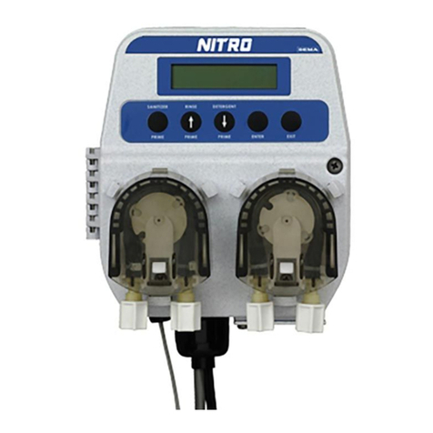
DEMA Nitro Parts list manual

DEMA
DEMA Nitro User manual
DEMA
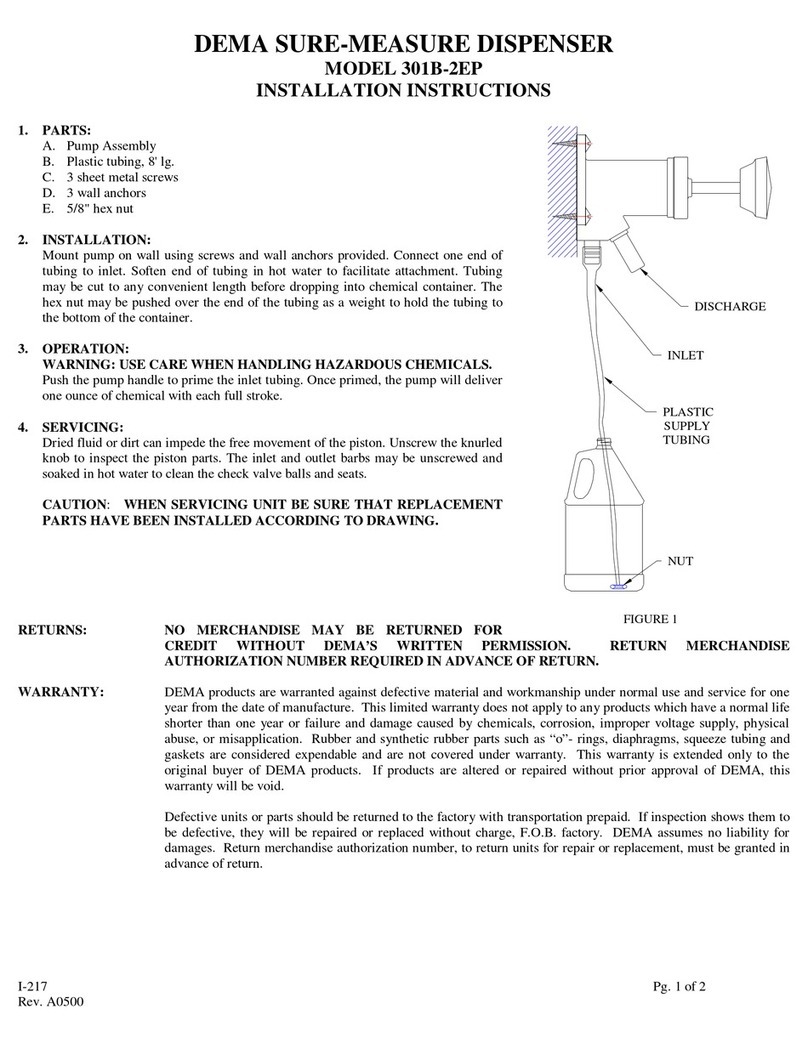
DEMA 301B-2EP User manual

DEMA
DEMA Nitro User manual
DEMA
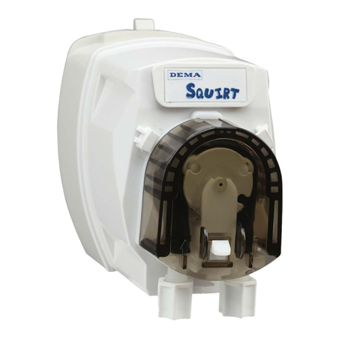
DEMA SQUIRT DRAIN UNIT User manual
DEMA
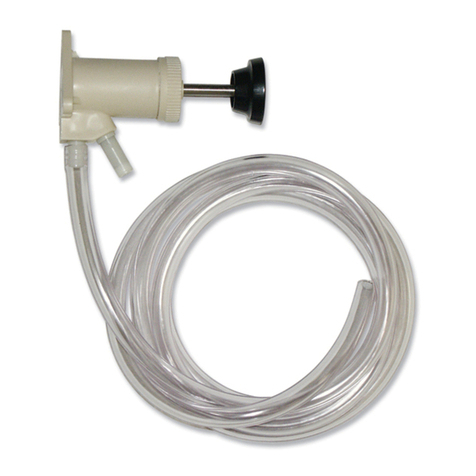
DEMA 301B-SY User manual
DEMA
DEMA TITAN II User manual
DEMA
DEMA 651GAP-1 User manual
