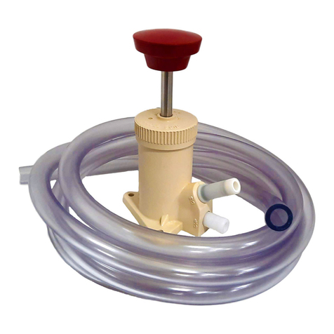
DEMA Olympian O-PDV User manual
Other DEMA Dispenser manuals
DEMA
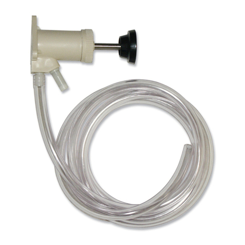
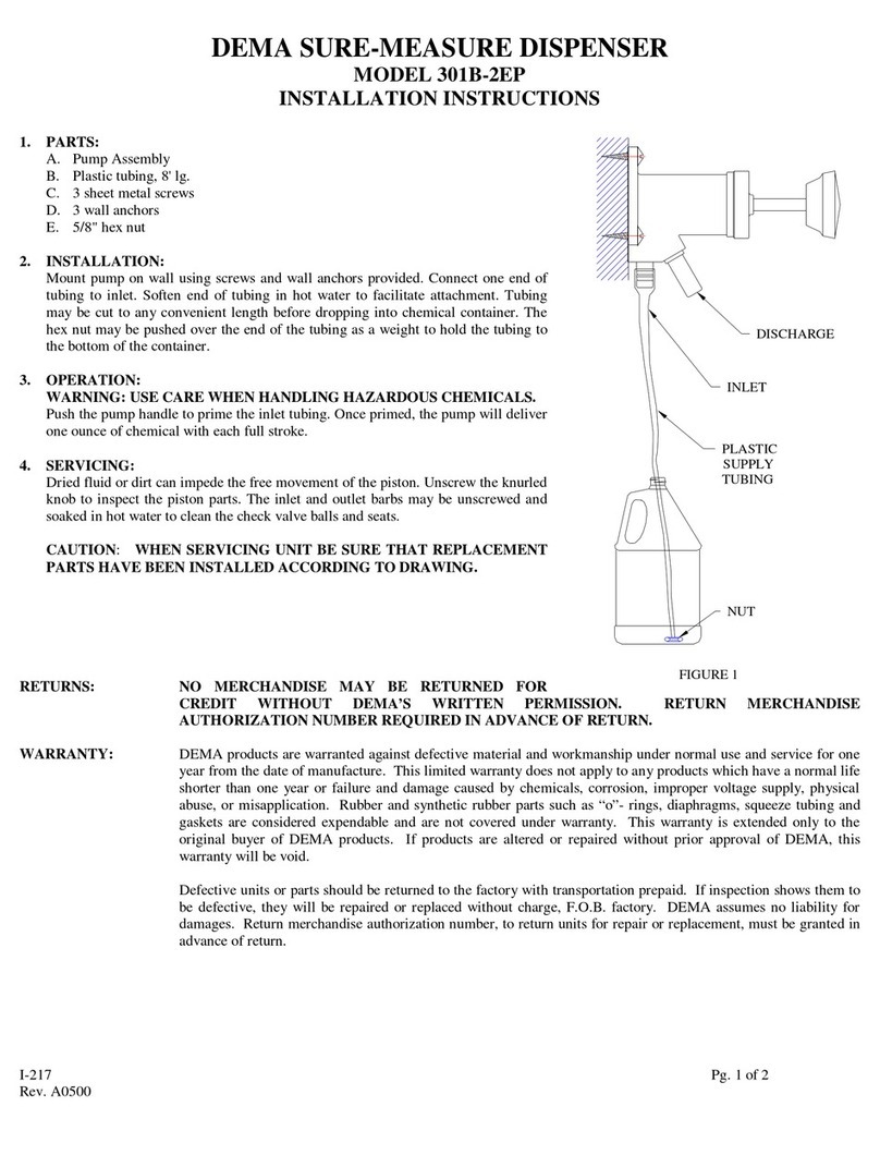
DEMA 301B-2EP User manual
DEMA
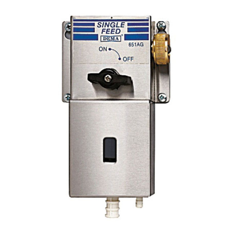
DEMA 651GAP-1 User manual
DEMA
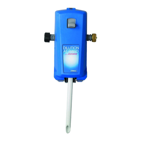
DEMA 801GAP User manual

DEMA
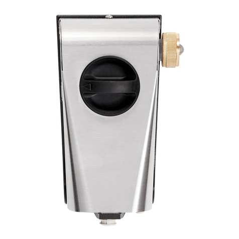
DEMA Laundry Master 830 User manual
DEMA
DEMA Super Sink Series Assembly instructions
DEMA
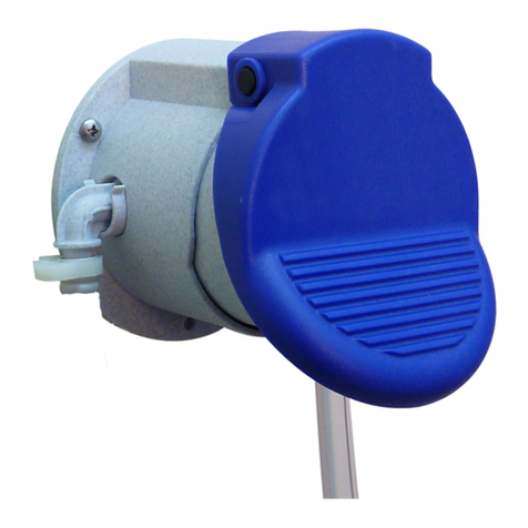
DEMA 302-1 User manual
DEMA
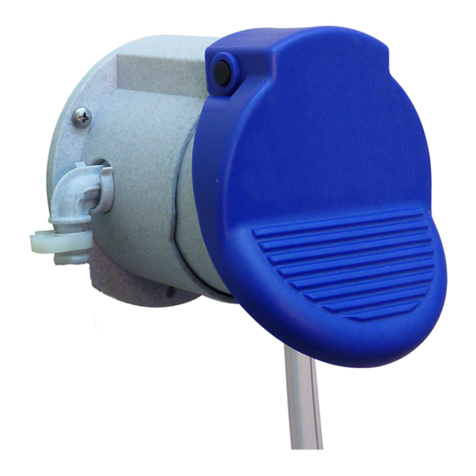
DEMA 302-2 User manual
DEMA
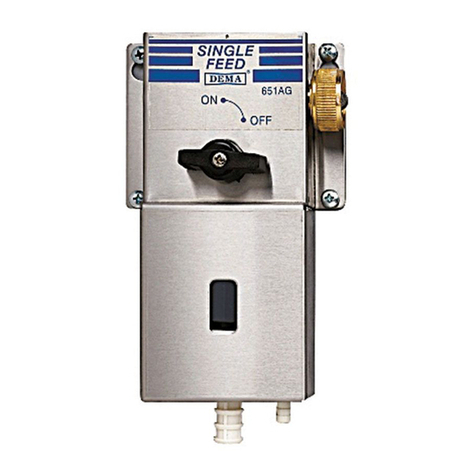
DEMA 651AG User manual
DEMA
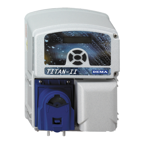
DEMA TITAN II User manual

DEMA
DEMA One User manual
DEMA
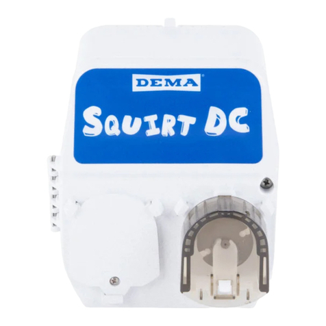
DEMA SQUIRT DC User manual

DEMA
DEMA 6300 User manual
DEMA
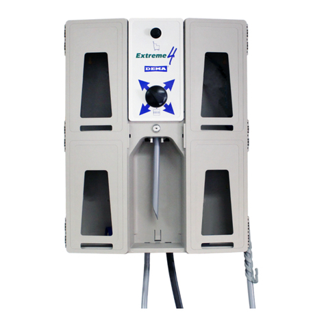
DEMA 665 Series User manual
DEMA
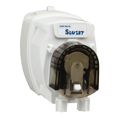
DEMA SQUIRT DRAIN UNIT User manual
DEMA
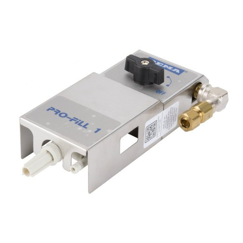
DEMA PF651GAP User manual

DEMA
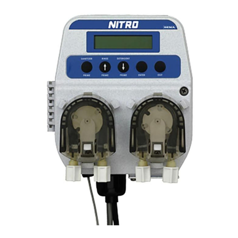
DEMA Nitro User manual

DEMA
DEMA TITAN II Assembly instructions
DEMA
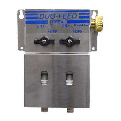
DEMA 652AG User manual
DEMA
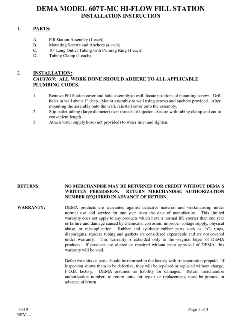
DEMA 607T-MC User manual
DEMA
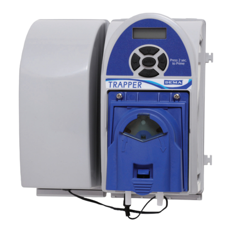
DEMA Trapper User manual
Popular Dispenser manuals by other brands
Franke
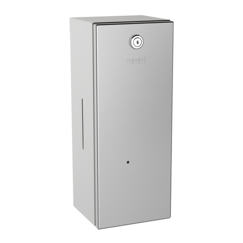
Franke RODX625 Installation and operating instructions
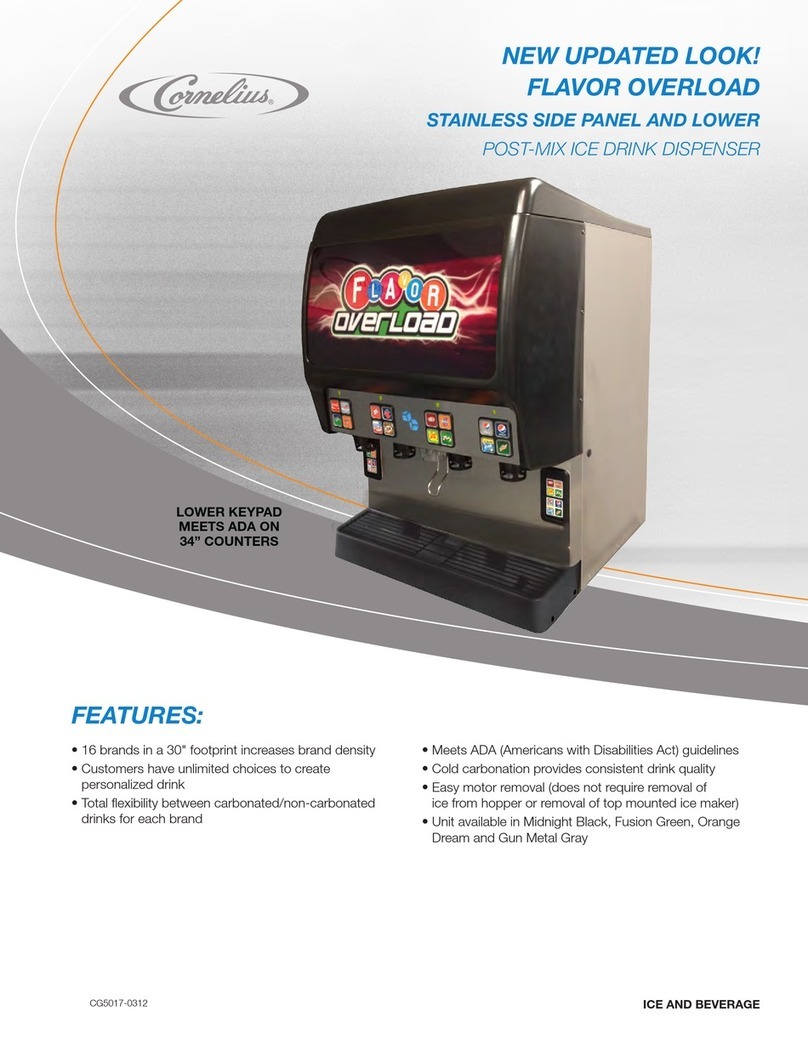
Cornelius
Cornelius Flavor OverLoad CG5017-1007 brochure
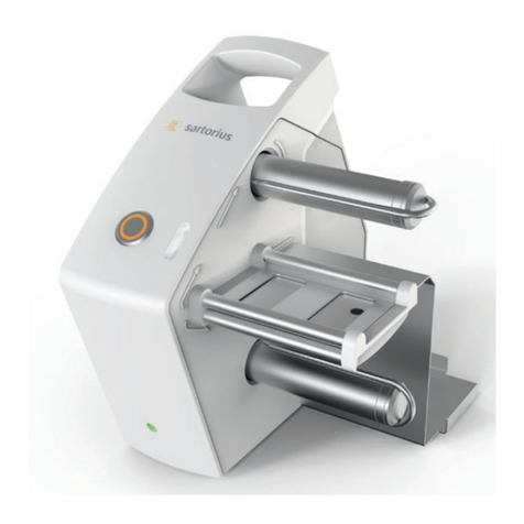
Sartorius
Sartorius Microsart e.motion 16713 BO operating instructions
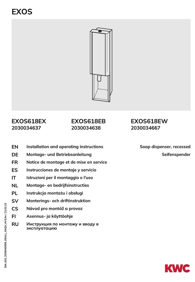
KWC
KWC EXOS EXOS618EX Installation and operating instructions

Franke
Franke RODX625 Installation and operating instructions
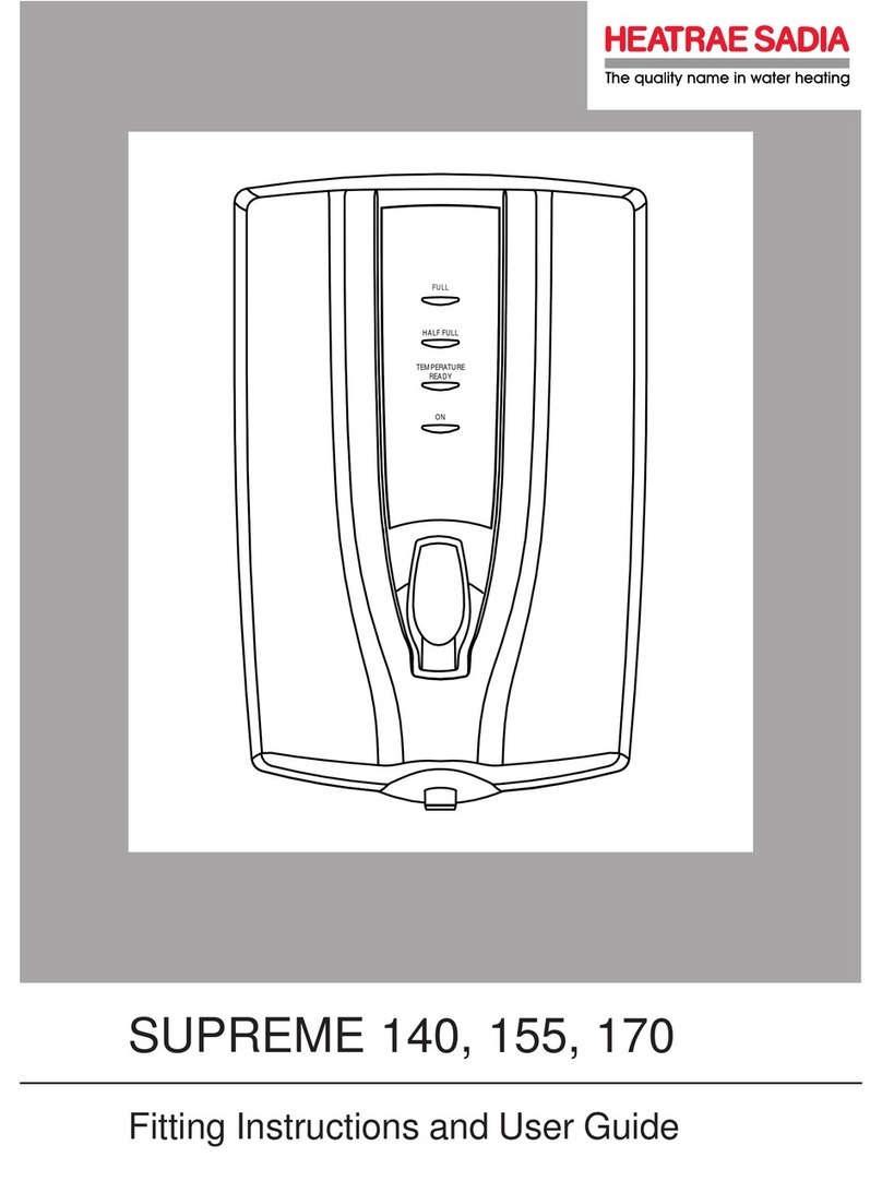
Heatrae Sadia
Heatrae Sadia SUPREME 140 Fitting instructions and user guide


