DEMA Extreme 4 User manual
I-1091
Rev. L-4
3
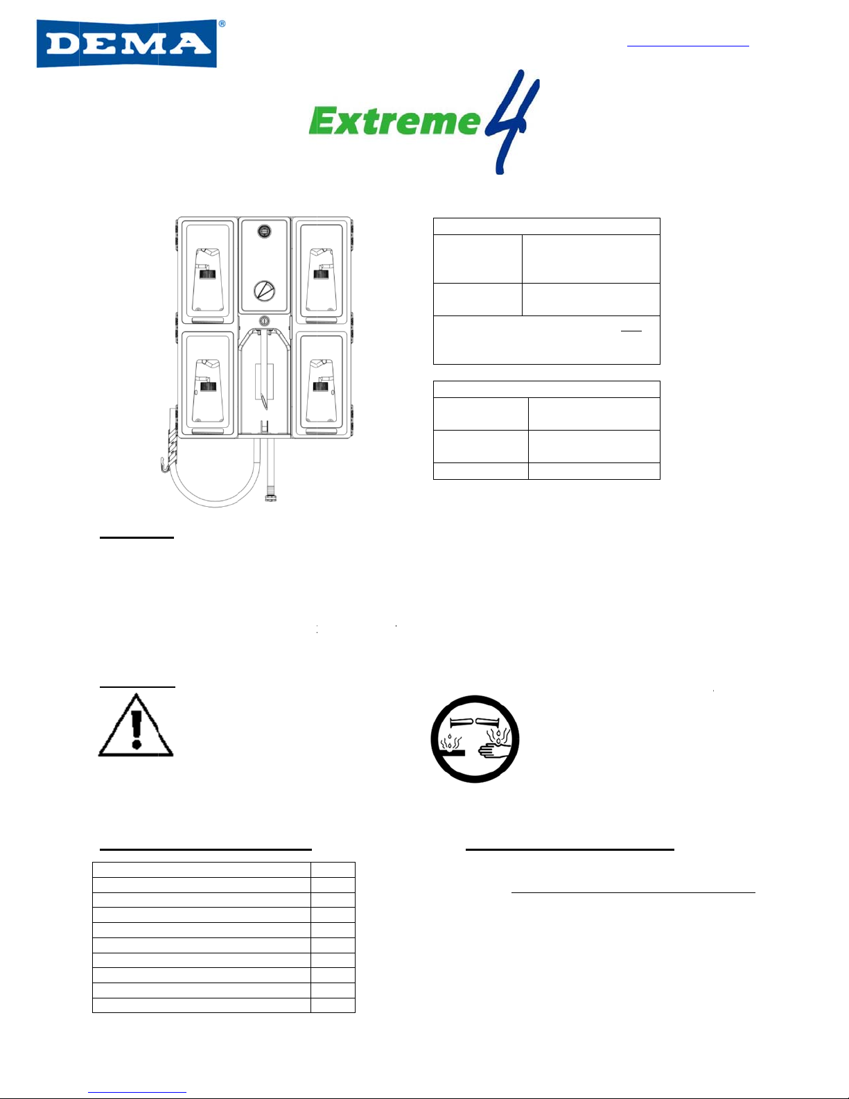
Overvi
e
The Extr
e
the great
A
sin
g
Multi-
Integ
r
Warnin
g
accordin
g
Wisconsi
n
of a pres
s
Instruc
t
Category
Package
C
Operation
a
Overall Di
m
Installatio
n
Operation
Metering
T
Troublesh
o
Parts List
Warranty I
n
3
223
e
w
e
me 4 makes
design featu
r
g
le dial for 8
d
point locking
r
ated ASSE
a
g
s
All inst
a
local pl
u
approv
e
devices
to be in
s
g
to local plu
m
n
and any ot
h
s
ure indicatin
g
t
ion Sheet
C
ontents / Req
u
a
l Requiremen
t
m
ensions
/ Preparation
T
ip Charts
o
oting
n
formation
users more
e
r
es include:
d
ifferent diluti
system for E
x
a
pproved bac
k
llations must
u
mbing code
s
e
d backflow p
. A pressure
s
talled with e
x
m
bing codes i
n
h
er state that
r
g
tee
Contents
u
ired Tools
t
s
e
fficient, fillin
g
on points
x
treme secu
r
k
flow preven
t
conform to
s
and use
revention
indicating te
e
x
isting faucet
n
the state of
r
equires the
u
Page
1
1
2
W
2-3
4
*
a
r
5
6
7
8
665 Se
r
g
bottles and
b
r
ity
t
ion
L
B
O
fi
l
e
is
s
u
se
O
Water Press
u
W
ater Temper
a
*
* Recommen
d
a
nd 70 psi. (5.
5
r
ecommended
Mete
r
k
665
s
disp
e
4 S
a
Bul
k
Ha
m
Drill
w
& 9/
3
P
e
r
ies Dispens
e
buckets with
arge sight wi
n
B
randing pan
e
O
ne-handed
b
ll
A
L
W
C
O
perationa
Water Sup
p
Mi
n
u
re 20 psi
a
ture
d
ed water pres
s
5
2 bar). If pre
s
that a water p
r
Box Co
n
r
ing tip
k
it har
d
s
eries
e
nser In
s
a
feLink cap a
k
tubing, 4 c
e
and foot
v
Suggeste
d
m
mer
w
/ 3/16”
3
2” bits
T
e
ncil
e
r
w
ease and qui
n
dow to iden
t
e
ls to meet th
b
ottle and opt
W
AYS WEA
R
C
LOTHING
A
WHEN WO
CHEMICA
L
l Require
m
p
ly Requirem
e
n
imum
(1.38 bar)
-
s
ure is betwee
s
sure exceeds
r
essure regula
t
n
tains
Mounting
d
ware, templ
a
& key set
s
truction she
e
a
ssemblies O
R
e
ramic weight
v
alves
d
Tools
Phillips
screwdriver
T
ape measur
e
Level
w
ww.demaen
g
1-800-325
Page
8
/
i
ckness. So
m
t
ify product a
n
e ‘look n’ fee
l
ional remote
R
PROTECTI
V
A
ND EYEWE
A
RKING WIT
H
L
PRODUCT
S
m
ents
e
nts Maximum
125 psi (8.62
b
150ºF (65.5
º
n 20 psi (1.38
b
70 psi, it is
t
or is used.
a
te
e
t
R
s
e
g
.com
-3362
1 of 8
/
29/17
m
e of
n
d level
l
’ need
bucket
VE
A
R
H
S
b
ar)**
º
C)
bar)

I-1091
Rev. L-4
3
Overall
Installa
t
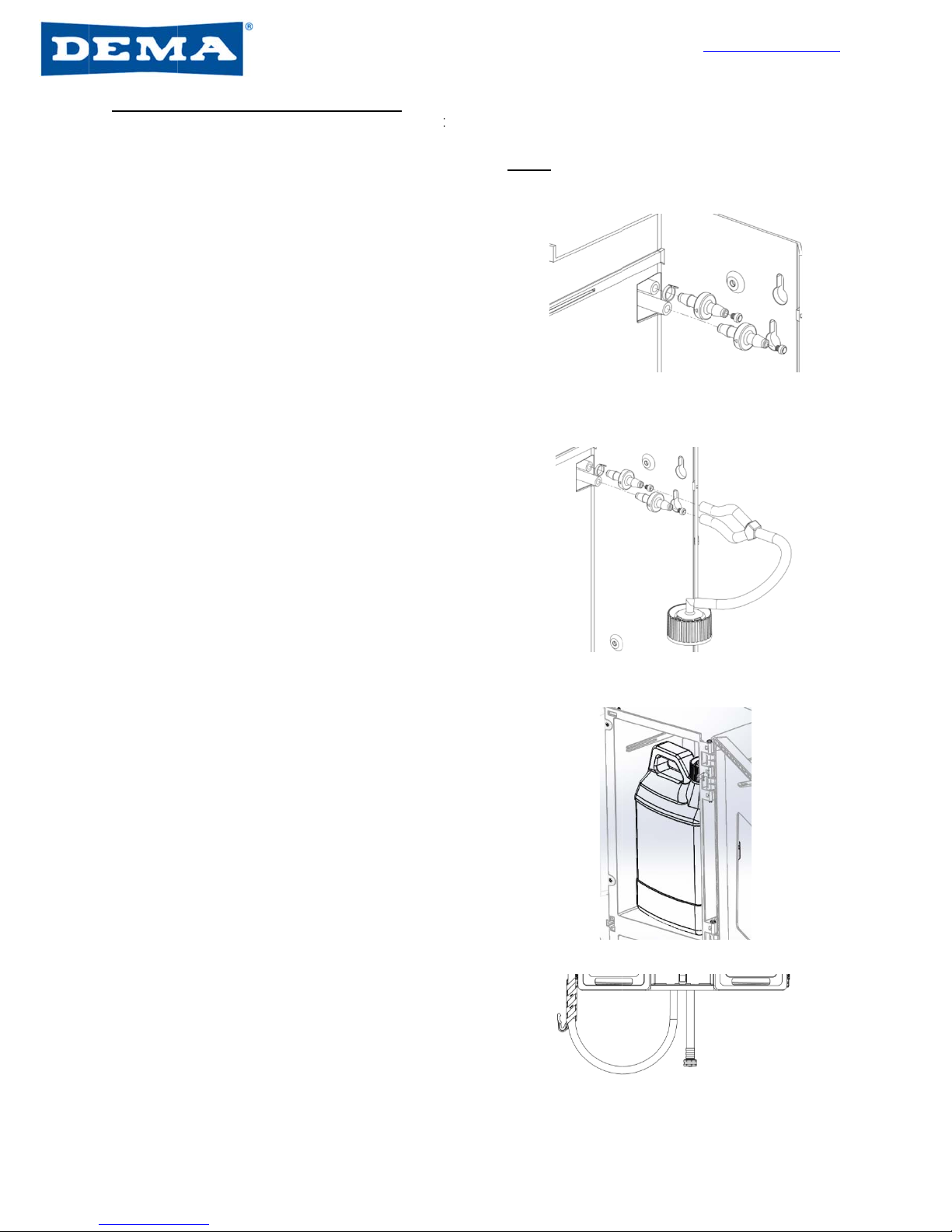
1. Identi
again
[For
a
2. Instal
top t
w
into t
h
3. Tight
e
4. Instal
tab in
[Opti
o
attac
h
chem
3
223
Dimensio
n
t
ion & Pre
p
fy desired lo
c
st wall and
m
a
ccuracy, us
e
l all four sup
p
w
o screws an
d
h
e anchors.
e
n screws ag
l Drip Tray b
y
back of drip
o
nal: Drill 3/1
6
h
¼” ID hose
ical from drip
n
s
p
aration
c
ation of disp
e
m
ark hole loc
a
e
level with te
m
p
lied anchors
d
hang dispe
n
a
inst dispen
s
y
sliding into
p
tray holder.
6
” hole into d
r
(not supplied
tray (Figure
e
nser. Rem
o
a
tions using t
h
m
plate to en
s
into marked
h
n
ser from the
s
er to assure
a
p
lace against
r
ip tray barb
a
) for draining
1)
o
ve cardboar
d
h
e template a
s
ure the disp
e
h
ole location
s
m. Install bot
t
a
secure fit.
a
nd
d
mounting t
e
a
s a guide.
e
nser is level
s
from step 1
.
tom two scre
w
w
e
mplate from
p
on the wall]
. Using supp
w
s through d
Figure 1
w
ww.demaen
g
1-800-325
Page
8
/
p
ackaging, p
l
p
lied screws, i
ispenser hol
e
g
.com
-3362
2 of 8
/
29/17
l
ace
nstall
e
s
I-1091
Rev. L-4
3
Installa
t
Step
s
valve
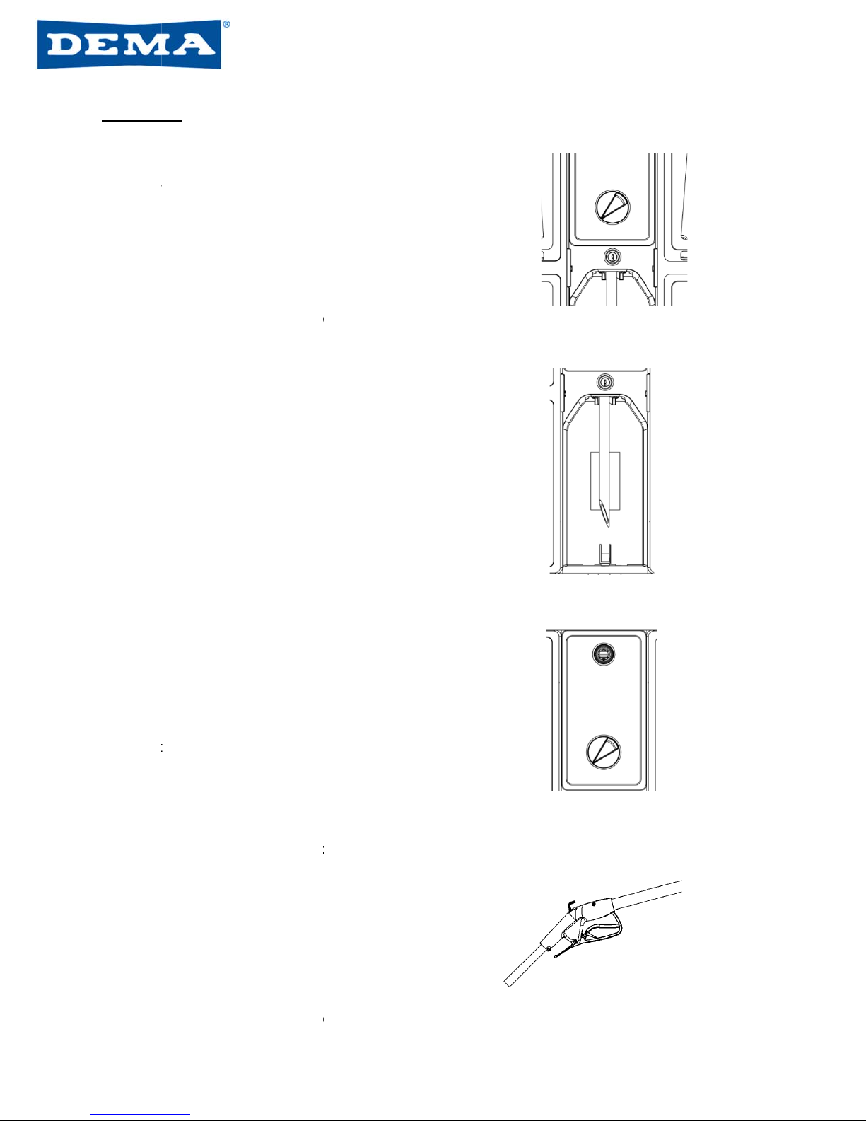
5. To in
s
chec
k
desir
e
rate
o
(Figu
r
6. Scre
w
threa
d
Note:
prod
u
7. For S
over
t
For
O
need
e
weig
h
Secu
r
valve
Note:
allow
8. Positi
comp
Safe
L
cera
m
9. Clos
e
10. Conn
sour
c
a pos
buck
e
3
223
t
ion & Pre
p
s
5 through
7
s located in
e
s
tall metering
k
valve in ea
c
e
d metering t
i
o
n the tip cha
r
r
e 2)
w
metering ti
p
d
ed check va
A blank tip c
u
ct from disp
e
afeLink cap
a
t
he exposed
c
O
pen contain
e
e
d and cut to
h
t and foot va
r
e top of tubi
n
barb
Softening th
e
the tube to fi
t
on chemical
c
artment in d
e
L
ink cap or in
s
m
ic weight int
o
e
and lock th
e
e
ct the suppl
i
c
e and activat
ition on the d
e
t or bottle fill
p
aration C
7
explain how
e
ach compart
m
tips, locate t
h
h compartm
e
p based on
c
r
t for bottle a
n
p
clockwise in
lve barb
a
n be used t
o
e
nsing at bottl
a
nd tubing: s
e
c
heck valve
b
e
r: Measure b
length. Inst
a
lve at base o
f
n
g over the e
x
e
tube with h
o
t
over the ba
r
c
ontainer int
o
e
sired positio
n
s
tall tubing w
o
open conta
i
e
cabinet doo
r
i
ed water ho
s
e
the dispen
s
ial and using
activation p
o
ont’d
to install me
t
m
ent. Chec
k
for
h
e correct
e
nt. Identify
c
olor and dilu
t
n
d bucket filli
n
to exposed
o
prevent a
e or bucket f
i
e
cure the tubi
b
arb (Figure
3
ulk tubing
a
ll ceramic
f
tubing.
x
posed chec
k
o
t water will
r
b with ease
o
each
n
and conne
c
foot valve a
n
i
ner (Figure
4
r
s
s
e to your wa
t
s
er by selecti
n
either the
o
int (Figure 5)
t
ering tips.
M
k
valves to bu
bottle fill do
n
t
ion
n
g
ll
ng
3
)
k
t
n
d
4
)
t
er
n
g
M
etering tips
w
u
cket fill have
n
ot.
w
w
ill be installe
a plastic rin
g
Figure 2
Figure 3
Figure 4
Figure 5
w
ww.demaen
g
1-800-325
Page
8
/
d at the two
c
g
, and check
v
g
.com
-3362
3 of 8
/
29/17
c
heck
v
alves
I-1091
Rev. L-4
3
Operati
1. Turn
t
chem
arro
w
2. Disp
e
bottle
trigg
e
3. For ri
n
the w
not d
r
1. Slide
raise
the b
o
2. To st
o
disen
3. Be c
a
as to
1. To st
a
butto
n
2. For c
o
3. To di
s
coun
t
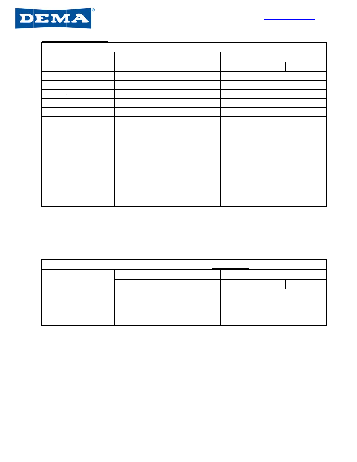
1. To st
a
trigg
e
2. For c
o
rotat
e
trigg
e
3. To di
s
and t
h
3
223
on
t
he chemical
ical position,
w
e
nse chemica
fill lever or b
e
r)
n
se water, p
o
a
ter symbol-
r
ink
the bottle tu
b
the bottle to
e
o
ttle fill asse
m
o
p filling, low
e
g
age
a
reful when r
e
not splash re
Dispens
a
rt the flow o
f
n
on unit abo
v
o
ntinuous flo
w
s
engage, rel
e
t
erclockwise
D
i
a
rt the flow o
f
e
r on handle
o
o
ntinuous flo
w
e
the red leve
r
e
r
s
engage, sim
h
e red lever
w
selector dial
t
indicated by
t
l by either ac
t
ucket fill butt
o
o
int the dial s
t
This is not p
o
Dispe
n
b
e inside the
s
e
ngage the u
-
m
bly
e
r the bottle
a
e
moving the
s
sidual chemi
c
er Activatio
n
f
diluted che
m
v
e selector di
w
, twist butto
n
e
ase button o
r
i
spenser Ac
t
f
diluted che
m
o
f fill gun
w
, while trigg
e
r
downward
a
ply press the
w
ill move out
o
Chemical
S
t
o the desire
d
t
he direction
a
t
ivating the
o
n (or remot
e
t
raight down
a
o
table water,
n
ser Activati
o
s
pray bottle
a
-
shaped leve
r
a
nd the lever
w
s
pray bottle s
o
c
al
n
Points – P
u
m
ical, press
al
n
clockwise
r
twist button
t
ivation Poin
m
ical, press
e
r is pressed
,
a
nd release
trigger agai
n
o
f position
S
elector Dia
d
a
l
e
fill
a
t
do
o
n Points –
B
a
nd
r
of
w
ill
o
u
sh Button
B
ts – Remote
,
n
l
(Figure 6)
B
ottle Fil
l
(F
i
B
ucket Fil
l
(
i
f
Fil
l
(
if equi
p
w
Figure 6
i
gure 7)
Figure 7
f
equipped
)
(
Figure 8
p
ped
)
(Figure
Figure 9
w
ww.demaen
g
1-800-325
Page
8
/
(
Figure 8)
9)
g
.com
-3362
4 of 8
/
29/17
I-1091
Rev. L-4
3
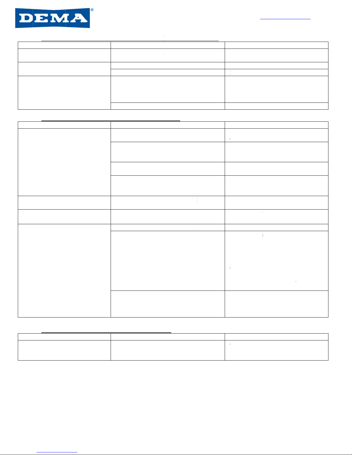
Meterin
Mete
r
Tan
Orange
Turquoi
s
Royal B
Charco
a
Pink
Light Bl
Brown
Red
White
Green
Blue
Yellow
Gray
No Tip
IN
Mete
r
Copper
Pumpki
n
Burgun
d
Lime
IN
3
223
g Tip Cha
r
r
ing Tip Col
o
s
e
lue
a
l Gray
ue
I
N
DUCTION R
A
r
ing Tip Col
o
n
d
y
I
N
DUCTION R
A
r
ts
Tab
o
r
1
G
Oz.
/g
1.2
5
1.7
0
2.1
5
2.3
7
2.6
7
3.0
0
3.9
0
4.5
5
5.8
0
7.0
0
7.9
0
9.8
0
14.
8
31.
6
35.
0
N
DUCTION
R
A
TES VARY
P
Table
o
r
1
G
Oz.
/g
0.5
6
0.7
3
0.9
0
1.2
8
N
DUCTION
R
A
TES VARY
P
le 1: Extrem
G
PM Flow R
a
g
al ml/
L
5
9.8
0
0
13.3
3
5
16.6
7
7
18.5
2
7
20.8
3
0
23.2
6
0
30.3
0
5
35.7
1
0
45.4
5
0
55.5
6
0
62.5
0
0
76.9
2
8
0 111.1
6
0 250.
0
0
0 277.
7
R
ATES BASE
D
P
RODUCT
T
2: Ultra Lea
n
G
PM Flow R
a
g
al ml/
L
6
4.3
8
3
5.7
0
0
7.0
3
8
10.0
0
R
ATES BASE
D
P
RODUCT
T
e 4 Meterin
g
a
te Proporti
o
L
Rati
o
0
1
0
3
7
5
7
6
0
2
5
4
3
4
8
6
4
3
0
3
3
1
2
8
5
2
2
6
1
8
0
1
6
2
1
3
1
9
0
0
4
7
8 3
.
D
ON WATE
R
T
O PRODUC
T
n
Metering
T
a
te Proporti
o
L
Rati
o
8
2
3
0
1
7
3
1
4
0
1
0
D
ON WATE
R
T
O PRODUC
T
g
Tips (Provi
d
o
ner
4
o
: 1 O
z
0
2 0
5 0
0 0
4 0
8 0
3 0
3 1
8 1
2 1
8 1
6 2
3 2
9
3
4
1
1
.
6 1
6
R
THIN PRO
T
. FIELD TE
S
T
ips (Not Pr
o
o
ner
4
o
: 1 O
z
3
0 0
7
5 0
4
3 0
0
0 0
R
THIN PRO
T
. FIELD TE
S
w
d
ed)
4
GPM Flow
z
./gal
m
.30 2
.
.40 3
.
.50 3
.
.56 4
.
.64 5
.
.75 5
.
.00 7
.
.12 8
.
.50 11
.75 1
3
.00 1
5
.50 1
9
.75 3
9
1
.50 9
0
6
.25 12
5
DUCTS (1 c
p
S
TS ARE R
E
o
vided)
4
GPM Flow
z
./gal
m
.16 1
.
.20 1
.
.26 2
.
.34 2
.
DUCTS (1 c
p
S
TS ARE R
E
w
ww.demaen
g
1-800-325
Page
8
/
Rate Propor
t
m
l/L R
a
.
34
.
13
.
91
.
39
.
00
.
88
.
81
.
77
.76
3
.70
5
.63
9
.61
9
.41
0
.91
5
.00
p
s)
E
COMMEND
E
Rate Propor
t
m
l/L R
a
.
25
.
56
.
03
.
66
p
s)
E
COMMEND
E
g
.com
-3362
5 of 8
/
29/17
t
ioner
a
tio : 1
427
320
256
228
200
170
128
114
85
73
64
51
34
11
8
E
D.
t
ioner
a
tio : 1
806
625
490
376
E
D.
S
y
m
p
Leak
i
p
rop
o
Leak
i
off)
Leak
i
S
y
m
p
Disp
e
any l
o
Disp
e
from
Che
m
p
rim
e
Disp
e
che
m
work
S
y
m
p
Prod
u
I-1091
Rev. L-4
3
Trouble
s
p
tom
i
ng at wa
t
er v
a
o
rtioner (dispe
n
i
ng at water v
a
i
ng at Action
G
Trouble
s
p
tom
e
nser won’t di
s
o
cations
e
nser is dispen
wrong positio
n
m
ical inlet tubi
n
e
d with chemi
c
e
nser does not
m
ical from cert
a
s at others
Trouble
s
p
tom
u
ct dilution is
t
3
223
s
hootin
g
:
W
a
lve to
n
ser is on)
a
lve (dispenser
G
ap (if equipp
e
s
hootin
g
: C
s
pense chemic
a
sing chemical
n
n
g does not st
a
c
al after use
dispense
a
in locations,
b
s
hootin
g
: P
r
t
oo weak or st
r
W
ater valve
o
Proble
m
Connec
is Connec
Water
p
e
d) Bucket
p
roport
i
Backfl
o
hemical not
Proble
m
a
l at Screen
w
clogge
d
Water
p
Minera
l
Selecto
r
Trans
m
a
y Check
v
b
ut Chemi
c
Loss o
f
drawin
g
Selecto
r
r
oduct dilut
i
Proble
m
r
ong Water
f
o
r backflow
p
m
tions are not t
i
tion to water
v
p
ressure is abo
v
fill tube is rai
s
i
oner
o
w preventer i
s
drawing pr
o
m
w
asher on wat
d
p
ressure is ins
u
l
deposits are
b
r
valve is not t
u
ission or selec
t
v
alves are wor
n
c
al bottle isn’t
d
f
vacuum is pr
e
g
r
valve is not t
u
i
on is incorr
e
m
f
low to dispen
s
p
reventer is
i
ght, tubing is
n
v
alve is loose
v
e acceptable
r
s
ed higher tha
n
s
faulty
o
perly
er supply hos
e
u
fficien
t
b
uilt up in pro
p
u
rning
t
or valve not e
n
n
and have fai
l
d
rawing prod
u
e
venting chemi
u
rning
e
ct
er is fluctuati
n
leaking
R
n
ot secure
S
t
i
T
r
ange I
n
n
E
o
D
p
R
R
e
is
R
r
e
V
2
a
p
ortione
r
S
m
V
v
R
ngaging
V
v
l
e
d
R
u
c
t
R
i
cal from
C
n
h
I
f
fo
I
f
v
V
v
R
R
n
g I
d
c
i
f
w
R
emed
y
S
ecure tubing
f
i
ghten clamps
T
ighten fitting
s
n
stall pressure
E
nsure dispens
e
o
f 36” off floo
r
D
o not raise b
u
p
roportione
r
R
eplace Actio
n
R
emed
y
R
emove scree
n
eplace
V
erify water p
r
2
0psi, remove
s
a
nd replace
S
oak proportio
n
m
ineral deposi
t
V
erify transmi
s
v
erify transmis
R
eplace trans
m
V
erify transmi
s
v
alves
R
eplace check
v
R
eplace bottle
i
C
heck for vac
u
n
one, check bo
t
h
ave vacuum t
h
f no vacuum,
r
f
or vacuum at
p
f you have va
c
v
alve, If none,
r
V
erify transmi
s
v
alves
R
eplace select
o
R
emed
y
deal water
p
re
s
c
hemical diluti
o
f
over 70psi, i
n
w
ww.demaen
g
1-800-325
Page
8
/
f
irmly against
c
s
at water valv
e
regulato
r
e
r is installed
a
r
u
cket fill tube
h
n
Gap backflo
w
n
washer, clea
n
r
essure is mini
m
s
creen washer,
n
er in delimer
t
s
s
sion aligns to
sion operates
a
m
ission
s
sion alignme
n
v
alves
i
n question wi
t
u
um at cap or f
o
t
h selector val
v
h
en replace ch
e
r
emove select
o
p
roportioner i
n
c
uum then repl
a
r
eplace propo
r
s
sion alignme
n
o
r valve(s)
s
sure range ac
c
o
n is 30psi to
7
n
stall pressure
g
.com
-3362
6 of 8
/
29/17
c
omponents,
e
a
t minimum
h
igher than
w
prevente
r
n
out and
m
um of
clean out
to clean off
selecto
r
s,
a
s intende
d
n
t to selector
t
h new one
o
ot valve, if
v
es, if you
e
ck valves
o
r and check
n
let
ace selector
r
tione
r
n
t to selector
c
urate
7
0psi max.,
regula
r
I-1091
Rev. L-4
3
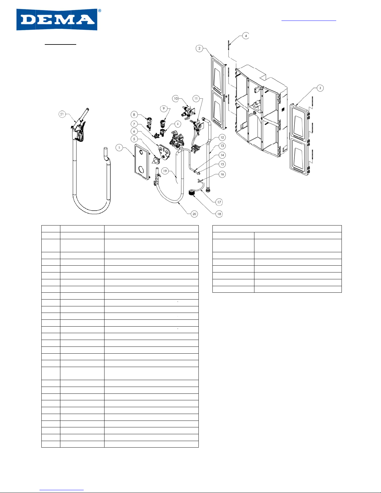
Parts li
s
No.
1
1
2
3
4
5
6
7
8
8 6
8 1
6
8
8
8 6
1
9
10
10
11
12
13 4
4
14
15
1
16
17
1
18 C
3
19
19
20 8
20
8
21
4
3
223
s
t
Part No.
14-3-3
14-3-2
14-2-3
14-2-4
10-47
66-339-1
63-53-15
63-53-12
61-99-4
1-32-AGP
6
3CHA-NB
61-45-4
61-22-4
1
-126AG-4
16-30
14-5-2
14-6-2
14-6-1
98-58-1
4
-3-6FCOS
11-72-1
1
00-12-18
66-500-2
1
00-12-19
3
8CR4W.00
66-242-1
66-242-2
9-30-GAP
8
5-15-29-6
4
0-736-3
D
e
Cover plate (
B
Cover plate (
R
operated)
Door – Left si
d
Door – Right
s
Hinge Pin
Knob
Transmission
Selector Asse
1 GPM Action
1 GPM Air G
a
2.5 GPM Acti
o
2.5 GPM Air
G
4 GPM Action
4 GPM Air G
a
Action Gap A
s
Push Button
V
Remote Gun
V
Bottle Fill Val
v
Lever Assem
b
6’ Black Hose
Strainer
Check Valve
(
7/32” Tubing,
Wye Adapter
7/32” Tubing,
SafeLink Cap
Bottle Fill Tub
e
Bottle Fill Tub
e
Bucket Fill Tu
b
Bucket Fill Tu
b
Remote Gun
A
e
scription
B
utton operate
d
R
emote gun
d
e
s
ide
Assembly
mbly
Gap Proporti
o
p Proportione
r
o
n Gap Propor
t
G
ap Proportion
e
Gap Proporti
o
p Proportione
r
s
sembly
V
alve Assembl
y
V
alve Assembl
v
e Assembly
b
ly
Assembly wit
h
Threaded)
2”
¼”
5”
Assembly
e
– Action Ga
p
e
– Air Gap
b
e – Action G
a
b
e – Air Gap
A
ssembly
d
)
o
ner
r
t
ioner
e
r
o
ner
r
y
y
h
p
a
p
Part No.
66-21K
100-15K-EX
4
10-57-2
100-16V-15
61-107-2
98-40-4
w
Parts Not
S
D
Keyset
4
Metering T
Drip Tray
Tubing &
F
Ceramic
W
Screw & A
n
w
ww.demaen
g
1-800-325
Page
8
/
S
hown
D
escription
ip Kit
F
oot Valve Ass
e
W
eight
n
chor Kit
g
.com
-3362
7 of 8
/
29/17
e
mbly

I-1091
Rev. L-4
3
Warran
t
Merchan
d
N
y
o
Product
W
D
a
n
a
n
c
h
a
s
c
o
If
D
s
h
D
g
r
a
b
3
223
t
y
d
ise Return
s
N
o merchandi
s
o
ur dealer fo
r
W
arranty
D
EM
A
’s prod
u
n
d service fo
r
n
y products t
h
h
emicals, co
r
s
“O”-rings, d
o
vered unde
r
products are
D
efective unit
s
h
ows them t
o
D
EM
A
assum
e
r
anted in ad
b
ove).
s
s
e will be ret
u
r
warranty iss
u
cts are warr
a
r
one year fr
o
h
at have a n
o
r
rosion, physi
c
iaphragms,
P
r
warranty. T
h
altered or re
s
or parts sh
o
o
be defecti
v
e
s no liabilit
y
vance of re
t
u
rned for cre
d
ues.
a
nted against
o
m the date o
f
o
rmal life sho
r
c
al abuse, or
P
VC tubing, a
h
is warranty i
paired witho
u
o
uld be return
e
v
e, they will
y
for damag
e
t
urned units
d
it without D
E
defective m
a
f
manufactur
e
r
ter than one
misapplicati
o
nd gaskets a
r
s extended
o
u
t prior appro
v
e
d to the fac
t
be repaired
o
e
s. Return
m
for repair o
r
E
MA’s written
a
terial and w
o
e
. This limite
d
year or failu
r
o
n. Rubber
a
re considere
d
o
nly to the ori
g
v
al of DEM
A
,
t
ory with tran
s
or replaced
w
m
erchandise
r
replaceme
n
w
permission.
o
rkmanship u
n
d warranty d
o
r
e and dama
g
a
nd synthetic
d
expendabl
e
g
inal buyer o
f
this warrant
y
s
portation pr
e
w
ithout char
g
authorizatio
n
n
t (See “Mer
c
w
ww.demaen
g
1-800-325
Page
8
/
Please cont
a
n
der normal
u
o
es not appl
y
g
e caused by
rubber parts
s
e
and are not
f
DEMA prod
u
y
is void.
e
paid. If insp
e
g
e, F.O.B. f
a
n
number m
u
c
handise Re
g
.com
-3362
8 of 8
/
29/17
a
ct
u
se
y
to
s
uch
u
cts.
e
ction
a
ctory.
u
st be
turns”
Table of contents
Other DEMA Dispenser manuals


DEMA
DEMA Master Nitro Express User manual

DEMA
DEMA Super Sink Series Assembly instructions

DEMA
DEMA TITAN II User manual

DEMA
DEMA Trapper User manual

DEMA
DEMA One User manual

DEMA
DEMA Olympian O-PDV User manual

DEMA
DEMA 693T FOAM STATION II User manual

DEMA
DEMA PF651GAP User manual

DEMA
DEMA Laundry Master 830 User manual

DEMA
DEMA 301B-C User manual


Popular Dispenser manuals by other brands


Kingnode
Kingnode E-404 Series operating manual

Silver King
Silver King Majestic SK12MAJ Technical manual and replacement parts list

START International
START International LD3500 quick start guide

Graco
Graco TI7700 Instructions-parts list

Kohler
Kohler K-9619 Installation and care guide

Loctite
Loctite PULSE EQ RC50 operating manual