manuals.online logo
Brands
  1. Home
  2. •
  3. Brands
  4. •
  5. Denon
  6. •
  7. Speakers System
  8. •
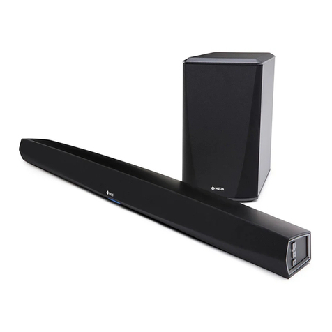
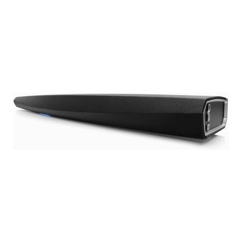
  9. Denon HEOS HS2 User manual

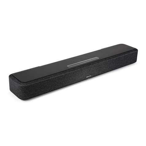
Denon HEOS HS2 User manual

Other manuals for HEOS HS2

2

This manual suits for next models

1

Other Denon Speakers System manuals

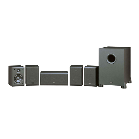
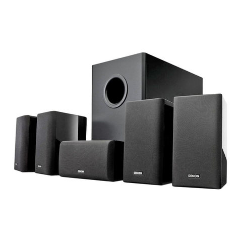
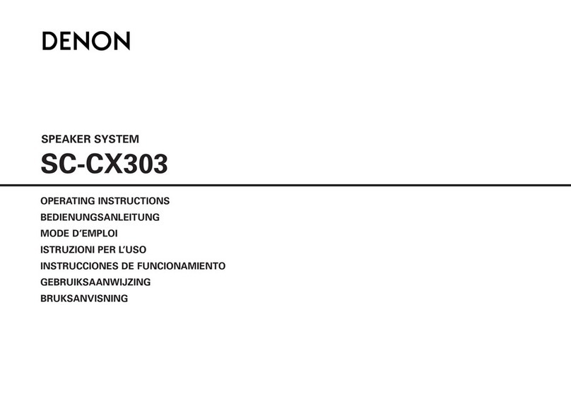
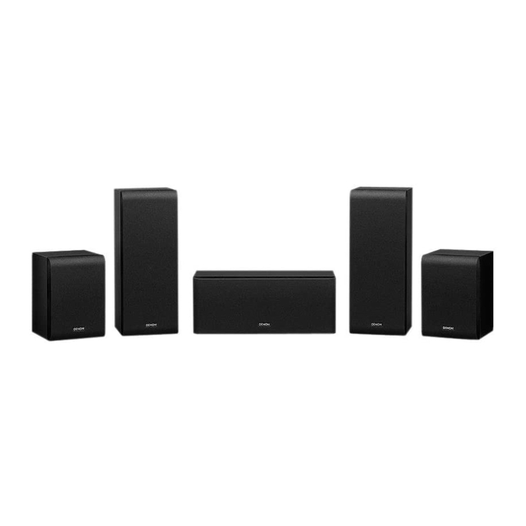
Denon SYS-65HT User manual

Denon

Denon SYS-65HT User manual

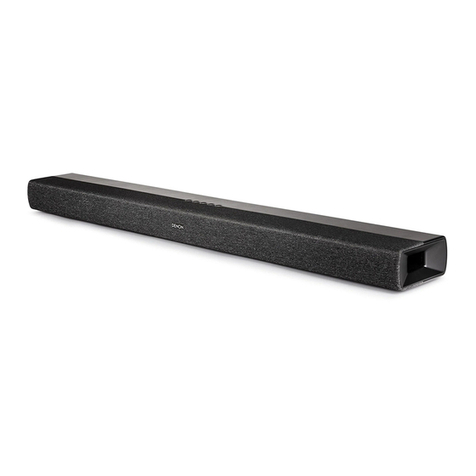
Denon HEOS Bar User manual

Denon

Denon HEOS Bar User manual

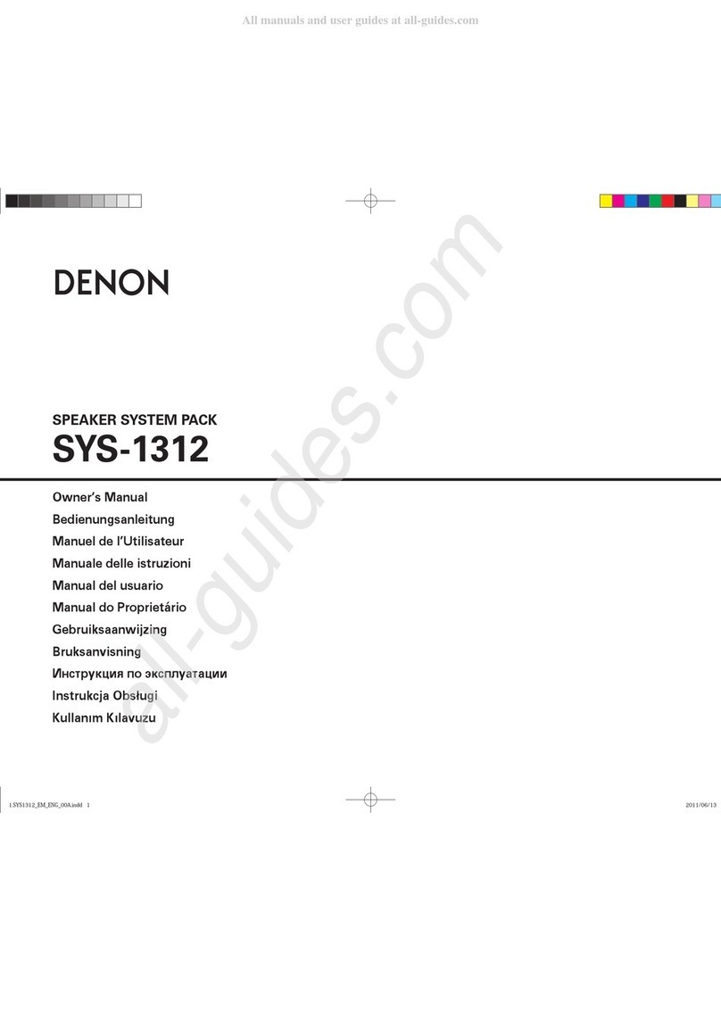
Denon SYS-1312 User manual

Denon

Denon SYS-1312 User manual

Denon DCD-F100 User manual

Denon

Denon DCD-F100 User manual

Denon HEOS HS2 User manual

Denon

Denon HEOS HS2 User manual

Denon DHT-S216 User manual

Denon

Denon DHT-S216 User manual

Denon SYS-76HT User manual

Denon

Denon SYS-76HT User manual

Denon DHT-S516H User manual

Denon

Denon DHT-S516H User manual

Denon DHT-S218 User manual

Denon

Denon DHT-S218 User manual

Denon DHT-S217 User manual

Denon

Denon DHT-S217 User manual

Denon SYS-57HT User manual

Denon

Denon SYS-57HT User manual

Denon DHT-S216 User manual

Denon

Denon DHT-S216 User manual

Denon DHT-S517 User manual

Denon

Denon DHT-S517 User manual

Denon DHT-S716H User manual

Denon

Denon DHT-S716H User manual

Denon SYS-391HT User manual

Denon

Denon SYS-391HT User manual

Denon SC-A33XG User manual

Denon

Denon SC-A33XG User manual

Denon SYS-C3L User manual

Denon

Denon SYS-C3L User manual

Denon DHT-C210 User manual

Denon

Denon DHT-C210 User manual

Denon HOME SOUND BAR 550 User manual

Denon

Denon HOME SOUND BAR 550 User manual

Denon DHT-S516 User manual

Denon

Denon DHT-S516 User manual

Denon SC-M53 User manual

Denon

Denon SC-M53 User manual

Denon DHT-S716H User manual

Denon

Denon DHT-S716H User manual

Denon DHT-S217 User manual

Denon

Denon DHT-S217 User manual

Denon SYS-57HT User manual

Denon

Denon SYS-57HT User manual

Popular Speakers System manuals by other brands

Monster MT-SB21 user manual

Monster

Monster MT-SB21 user manual

Monacor ESP-76AB/ WS manual

Monacor

Monacor ESP-76AB/ WS manual

Samsung HW-J430 user manual

Samsung

Samsung HW-J430 user manual

WILSON AUDIO WATT owner's manual

WILSON AUDIO

WILSON AUDIO WATT owner's manual

Hisense AX3125H user manual

Hisense

Hisense AX3125H user manual

EisSound KBSound iSelect user manual

EisSound

EisSound KBSound iSelect user manual

Boston Acoustics VRi793 manual

Boston Acoustics

Boston Acoustics VRi793 manual

Sven SPS-707bL Operation manual

Sven

Sven SPS-707bL Operation manual

Monacor DSM-26LAN instruction manual

Monacor

Monacor DSM-26LAN instruction manual

JVC CS-SR100 instructions

JVC

JVC CS-SR100 instructions

Samsung HW-C450 user manual

Samsung

Samsung HW-C450 user manual

TaoTronics evatronic ET-SK011 user guide

TaoTronics

TaoTronics evatronic ET-SK011 user guide

JVC HX-D7C instructions

JVC

JVC HX-D7C instructions

Pyle PBMSPG190 user manual

Pyle

Pyle PBMSPG190 user manual

Sven SPS-607 Operation manual

Sven

Sven SPS-607 Operation manual

iSP Technologies LT2 series owner's manual

iSP Technologies

iSP Technologies LT2 series owner's manual

Samsung Crystal Surround Air Track HW-F550 user manual

Samsung

Samsung Crystal Surround Air Track HW-F550 user manual

Bose Acoustimass 6 Series II owner's guide

Bose

Bose Acoustimass 6 Series II owner's guide

manuals.online logo
manuals.online logoBrands
  • About & Mission
  • Contact us
  • Privacy Policy
  • Terms and Conditions

Copyright 2025 Manuals.Online. All Rights Reserved.

WIRELESS TV SOUND SYSTEM
HEOS HomeCinema HS2
DENON DHT-S516H
Service Manual
Click here!
On-line service parts list
HomeCinema HS2: http://dmedia.soundunited.com/documents/details/23919
DHT-S516H: http://dmedia.soundunited.com/documents/details/26095
ONLINE PARTS LIST (P5)
WEB owner’s manual
EM: http://manuals.denon.com/HEOSHCHS2/ALL/EN/index.php
NA: http://manuals.denon.com/DHTS516H/NA/EN/index.php
EU: http://manuals.denon.com/DHTS516H/EU/EN/index.php
JP: http://manuals.denon.com/DHTS516H/JP/JA/index.php
BEFORE SERVICING THIS UNIT
ELECTRICAL
MECHANICAL
REPAIR INFORMATION
UPDATING
Ver. 5
Condential
g
•Forpurposesofimprovement,specicationsanddesignaresubjecttochangewithoutnotice.
•Pleaseusethisservicemanualwhenreferringtotheoperatinginstructionswithoutfail.
•Someillustrationsusedinthisservicemanualareslightlydifferentfromtheactualproduct.
Please refer to the MODIFICATION NOTICE.
BEFORE SERVICING THIS UNIT
SAFETY PRECAUTIONS
NOTE FOR SCHEMATIC DIAGRAM
HANDLING THE SEMICONDUCTOR AND OPTICS
ONLINE PARTS LIST
Accessing the Parts List
Searching Part Numbers or Ref. Numbers
NOTE FOR PARTS LIST
SERIAL NUMBER
Serial Number Organization
SKU Code of this Unit
Before Servicing
This Unit Electrical Mechanical Repair Information Updating
2
SAFETY PRECAUTIONS
The following items should be checked for continued protection of the customer and the service technician.
Leakage current check
Before returning the set to the customer, be sure to carry out either (1) a leakage current check or (2) a line to chassis resistance check. If the leakage current exceeds 0.5 milliamps, or if the resistance from chas-
sis to either side of the power cord is less than 460 kohms, the set is defective.
Be sure to test for leakage current with the AC plug in both polarities, in addition, when the set's power is in each state (on, off and standby mode), if applicable.
CAUTION Please heed the following cautions and instructions during servic-
ing and inspection.
◎ Heed the cautions!
Cautions which are delicate in particular for servicing are labeled on the cabinets, the parts and the
chassis, etc. Be sure to heed these cautions and the cautions described in the handling instructions.
◎ Cautions concerning electric shock!
(1) An AC voltage is impressed on this set, so if you touch internal metal parts when the set is energized,
you may get an electric shock. Avoid getting an electric shock, by using an isolating transformer and
wearing gloves when servicing while the set is energized, or by unplugging the power cord when
replacing parts, for example.
(2) There are high voltage parts inside. Handle with extra care when the set is energized.
◎ Caution concerning disassembly and assembly!
Through great care is taken when parts were manufactured from sheet metal, there may be burrs on the
edges of parts. The burrs could cause injury if ngers are moved across them in some rare cases. Wear
gloves to protect your hands.
◎ Use only designated parts!
The set's parts have specic safety properties (re resistance, voltage resistance, etc.). Be sure to use
parts which have the same properties for replacement. The burrs have the same properties. In particular,
for the important safety parts that are indicated by the z mark on schematic diagrams and parts lists,
be sure to use the designated parts.
◎ Be sure to mount parts and arrange the wires as they were originally placed!
For safety seasons, some parts use tapes, tubes or other insulating materials, and some parts are mount-
ed away from the surface of printed circuit boards. Care should also be taken with the positions of the
wires by arranging them and using clamps to keep them away from heating and high voltage parts, so
be sure to set everything back as it was originally placed.
◎ Make a safety check after servicing!
Check that all screws, parts and wires removed or disconnected when servicing have been put back
in their original positions, check that no serviced parts have deteriorated the area around. Then make
an insulation check on the external metal connectors and between the blades of the power plug. And
otherwise check that safety is ensured.
(Insulation check procedure)
Unplug the power cord from the power outlet, disconnect the antenna, plugs, etc., and on the power.
Using a 500V insulation resistance tester, check that the insulation resistance value between the inplug
and the externally exposed metal parts (antenna terminal, headphones terminal, input terminal, etc.) is
1M Ω or greater. If it is less, the set must be inspected and repaired.
Many of the electric and the structural parts used in the set have special safety properties. In most cases
these properties are difcult to distinguish by sight, and the use of replacement parts with higher rat-
ings (rated power and withstand voltage) does not necessarily guarantee that safety performance will
be preserved. Parts with safety properties are indicated as shown below on the wiring diagrams and the
parts list in this service manual. Be sure to replace them with the parts which have the designated part
number.
(1) Schematic diagrams Indicated by the z mark.
(2) Parts lists Indicated by the z mark.
The use of parts other than the designated parts could cause electric shocks, res or other dangerous
situations.
CAUTION Concerning important safety parts
Before Servicing
This Unit Electrical Mechanical Repair Information Updating
3
WARNING:
Parts indicated by the z mark have critical characteristics. Use ONLY replacement parts recommended
by the manufacturer.
CAUTION:
Before returning the set to the customer, be sure to carry out either (1) a leakage current check or (2)
a line to chassis resistance check. If the leakage current exceeds 0.5 milliamps, or if the resistance from
chassis to either side of the power cord is less than 460 kohms, the set is defective.
WARNING:
DO NOT return the set to the customer unless the problem is identied and remedied.
NOTICE:
(1) ALL RESISTANCE VALUES IN OHM. k=1,000 OHM / M=1,000,000 OHM
(2) ALL CAPACITANCE VALUES ARE EXPRESSED IN MICRO FARAD, UNLESS OTHERWISE INDICATED. P
INDICATES MICRO-MICRO FARAD. N INDICATES NANO FARAD.
(3) EACH VOLTAGE AND CURRENT ARE MEASURED AT NO SIGNAL INPUT CONDITION.
(4) CIRCUIT AND PARTS ARE SUBJECT TO CHANGE WITHOUT PRIOR NOTICE.
Electrostatic breakdown of the semi-conductors or optical pickup may occur due to a potential differ-
ence caused by electrostatic charge during unpacking or repair work.
1. Ground for Human Body
Be sure to wear a grounding band (1 M ohm) that is properly grounded to remove any static electricity
that may be charged on the body.
2. Ground for Workbench
Be sure to place a conductive sheet or copper plate with proper grounding (1 M ohm) on the work-
bench or other surface, where the semi-conductors are to be placed. Because the static electricity
charge on clothing will not escape through the body grounding band, be careful to avoid contacting
semi-conductors with your clothing
<Incorrect>
CBA
Grounding Band
Conductive Sheet or
Copper Plate
1MΩ
1MΩ
<Correct>
CBA
NOTE FOR SCHEMATIC DIAGRAM
HANDLING THE SEMICONDUCTOR AND OPTICS
Before Servicing
This Unit Electrical Mechanical Repair Information Updating
4
ONLINE PARTS LIST
Accessing the Parts List
(1) Access from the Service Manual
・ Click the URL link on the cover of the service manual.
Examples of display
NOTE : If the web browser does not open automatically, copy the URL and paste it into the address bar
of the web browser and then press Enter.
(2) Accessing the Part List from the Model Asset Screen.
・ Display Model Asset from New SDI.
・ Click the section displayed as ▼ Link to Part Lists under the model name.
NOTE : If the ▼ Link to Parts List section is not displayed, download the parts table from the Asset list.
Searching Part Numbers or Ref. Numbers
You can search a Parts List for part numbers or Ref. numbers.
(1) Enter the part number or Ref. number in the search window of the Parts List, and press the search
button.
(2) The search results are displayed.
The name of the sheet in which the search part is used and the part’s line are displayed.
(3) Next, click the "Sheet" section of the search results.
1. Parts indicated by "nsp" on this table cannot be supplied.
2. When ordering a part, make a clear distinction between "1" and "I" (i) to avoid mis-supplying.
3. A part ordered without specifying its part number can not be supplied.
4. Part indicated by "@" mark is not illustrated in the exploded and packaging view.
WARNING: Parts indicated by the z mark have critical characteristics. Use ONLY replacement parts
recommended by the manufacturer.
NOTE FOR PARTS LIST
Before Servicing
This Unit Electrical Mechanical Repair Information Updating
5
SKU Code of this Unit
Product SKU SKU Code
HEOSHCHS2BKE3 AWB
HEOSHCHS2BKE2 AWA
HEOSHCHS2K AWC
DHTS516HBKE2 BMP
DHTS516HBKE3 BMN
DHTS516HK BMQ
g
SERIAL NUMBER
Serial Number Organization
The 14-digit serial number that contains the code of the manufacturing plant and the manufacturing
date.
SKU
code
14 digits
Factory
code
Cumulative
serial number
Manufactured
Year, month
The last
2digit of year Month
(01 ~ 12)
Before Servicing
This Unit Electrical Mechanical Repair Information Updating
6
ELECTRICAL
SCHEMATIC DIAGRAMS
SCH01 SoundBar Main PCB LEGO
SCH02 SoundBar Main PCB PCM921
SCH03 SoundBar Main PCB AUX IN
SCH04 SoundBar Main PCB MCU
SCH05 SoundBar Main PCB DSP1-1
SCH06 SoundBar Main PCB DSP2-2
SCH07 SoundBar Main PCB CONNECTORS
SCH08 SoundBar Main PCB POWER
SCH09 SoundBar Main PCB Power Amplier
SCH10 SoundBar Main PCB CPLD
SCH11 SoundBar HDMI PCB 1/2
SCH12 SoundBar HDMI PCB 2/2
SCH13 SoundBar AC PCB
SCH14 SoundBar USB PCB
SCH15 SoundBar LED PCB
SCH16 SoundBar KEY PCB
SCH17 Subwoofer MAIN PCB
PRINTED CIRCUIT BOARDS
For SoundBar MAIN, HDMI, USB, AC, LED, KEY
For Subwoofer MAIN
BLOCK DIAGRAM and POWER DIAGRAM for
SoundBar
BLOCK DIAGRAM and POWER DIAGRAM for
Subwoofer
WIRING DIAGRAM for SoundBar
WIRING DIAGRAM for Subwoofer
Remote Code Table
Before Servicing
This Unit Electrical Mechanical Repair Information Updating
7
SCHEMATIC DIAGRAMS
SCH01 SoundBar Main PCB LEGO
g
AUX_DETECTP7[7B]
MUTE_LEDP7[3B]
CM_CTSP4[6C]
nUSB_FAULT_0P1[1D]
EASY_SETUP_TX2P3[2B]EASY_SETUP_TXP3[2B]
STBY_STATUSP4[6C]
USB_DNP7[2A]
USB_DPP7[2A]
TPO-P7[2A]
TPO+P7[2A]
TPI+P7[2A]
TPI-P7[2A]
MCU_RESETP4[2C], P4[3B]
HEOS_I2S0_LRCKP10[5A]
HEOS_I2S0_BCKP10[5A]
CM_SSOP4[8B]
CM_MISOP4[6B]
CM_SCKP4[6B]
BIAS_DETECTP7[7B]
HEOS_I2S0_DATAP10[5A]
HEOS_I2S0_MCKP10[5A]
3.3VDCORE
3.3VDCORE
3.3VDCORE
10K
0402
R12
10K
0402
R46
10K
0402
R30
USB_HPEN_0P1[1D]
5VDCORE
5VDCORE
CM_RXDP4[1B], P4[6C]
CM_TXDP4[1C], P4[6C] CM_RTSP4[5B]
WPS_LED_ONP7[7B]
3.3VDCORE
3.3VDCORE
3.3VDCORE
3.3VDCORE
CONNECTP4[4B], P7[7B]
VOL+ P4[4B], P7[2B]
VOL-P4[4B], P7[2B]
MUTE P4[4B], P7[2B]
3K3
0402
R59
3K3
0402
R60
3K3
0402
R61
HEOS_I2S2_BCKP2[3C]
HEOS_I2S2_LRCKP2[3C] HEOS_I2S2_DATAP2[3C]
22R
R5
22R
R6
22R
R7
3K3
0402
R56
MCU_BTMDP4[1B], P4[2B] 22R
R20
22R
R25
22R
R32
22R
R33
22R
R1
22R
R3
3.3VDCORE
BT_PAIR P4[4B], P7[7B]
3K3
0402
R47
LMBT3904LT1G
SOT-23
1
32
Q7
10K
0402
R42
10K
0402
R45
4K7
0402
R34
3.3V_EVER
GND
1%10K
0402
R48
1%10K
0402
R49
1%10K
0402
R50
GND
100pF
50V
C9
22R
R26
22R
R8
22R
R2
DNI
R36 0RR37
1%300R
0603
R54
2.2uF
6.3V
C1
2.2uF
6.3V
C2
4K7
0402
R40
GND
BAT54C
2
3
1
D5
BAT54C
2
3
1
D7
BAT54C
2
3
1
D8
BAT54C
2
3
1
D9
BAT54C
2
3
1
D10
KEYINP4[5B]
3.3V_EVER
3K3
0402
R51
RSB6.8SM
1
2
D2
RSB6.8SM
12
D6
RSB6.8SM
12
D3
RSB6.8SM
12
D4
10nFC 12
10nF
C 13
10nF
C 14
10nF
C 11
10nF
C 10
10nF
C 15
10nF
C 16
10nF
C 7
10nF
C 8
LMBT3904LT1G
SOT-23
1
32
Q6
10K
0402
R24
10nF
16V
C5
GND
10nF
16V
C6
10K
0402
R35
GND
GND
10nF
16V
C4
3.3V_EVER
PWM0
1PWM1 2
PWM2
3VDD4
VDD
5VDD6
MCLK_I2S_0
7SPDIF_OUT8
GND
9GND10
WS_I2S_0
11 SDIN_I2S_0 12
BITCLK_I2S_0
13 SDOUT_12S_0 14
GND
15 GND16
WS_I2S_1
17 SDIN_I2S_1 18
BITCLK_I2S_1
19 SDOUT_12S_1 20
GND
21 GND22
WS_I2S_2
23 SDIN_I2S_2 24
BITCLK_I2S_2
25 SDOUT_I2S_226
GND
27 GND28
12C0_SDA
29 USB2_P2_DM30
12C0_SCL
31 USB2_P2_DP 32
GND
33 GND34
I2C1_SDA
35 TDN_PHY0_CH136
I2C1_SCL
37 TDP_PHY0_CH138
SPI0_SS
39 TDN_PHY0_CH040
SPI0_MISO
41
GND
43
SPI0_CLK
45
UART1_TX
47
UART1_RX
49
USB2_VBUS_EN
51
GPIO_02
53
GPIO_04
55
GPIO_06/GND
57
GPIO_08
59
GPIO_10
61
GPIO_12
63
GPIO_14
65
GPIO_16
67
GPIO_18
69
GPIO_20
71
GPIO_22
73
GPIO_24/GND
75
ADC_AUXIN_0
77
ADC_AUXIN_2
79
TDP_PHY0_CH042
GND44
SPI0_MOSI/GPIO_29 46
UART1_RTS/GPIO_3048
UART1_CTS50
PWM3 52
GPIO_0354
GPIO_0556
GPIO_07/GND58
GPIO_0960
GPIO_1162
GPIO_1364
GPIO_1566
GPIO_1768
GPIO_1970
GPIO_2172
FCT_RST74
GPIO_25/ADC_BIAS76
ADC_AUXIN_178
ADC_AUXIN_380
J6
DNI
0603
R15
TP4
TP6
TP10
TP11
TP16
TP20
TP5
TP12
TP17
TP18
TP19
TP21
DNIR38
DNI
0402
R14
LEGO MODULE
NETWORK_RP7[7B]
NETWORK_BP7[7B]
NETWORK_GP7[7B]
HEOS_I2S0_BCK
HEOS_I2S0_LRCK
CONNECT_BUTTON_CORE
CONNECT_BUTTON_CORE
MUTE_BUTTON_CORE
MUTE_BUTTON_CORE
VOL+_BUTTON_CORE
VOL-_BUTTON_CORE
VOL+_BUTTON_CORE
VOL-_BUTTON_CORE
MB_REVISION MB_TYPE
MB_TYPE
MB_REVISION2
MB_REVISION2
MB_REVISION
LED_ACT1
MODULE_AWAKE
BT_PAIR_BUTTON_CORE
CM_MOSI P4[6B], P4[7C]
CMWAKEUPP4[4C]
BT_PAIR_BUTTON_CORE
Short Circuit Current Limit: 2.275A
USB CHARGE PORT CONTROLLER
3.3VDCORE
0.1uF
C18
nUSB_FAULT_0P1[5B]
USB_HPEN_0P1[5B]
3.3VDCORE3.3VDCORE
1uF
25V
C21
3.3VDCORE
80.6K
0402
R72
10K
0402
R69
10K
0402
R70
0R
R75
0R
R76
0R
R80
DNI
R73
0RR74
DNI
R81
27K
0402
R71
5VDCORE120R@100MHz
FB1
VBUS P7[2A]
0.01uF
50V
C23
1nF
50V
C22
0.1uF
C24
GND
GND
10K
0402
R78
10K
0402
R77
10K
0402
R68
10K
0402
R79
22uF
10V
C20
22uF
10V
C19
TPS2546
IN
1
DM_OUT2
DP_OUT3
ILIM_SEL
4
EN
5
CTL1
6
CTL2
7
CTL3
8
STATUS
9
DP_IN10
DM_IN11
OUT12
FAULT
13 GND14
ILIM_LO 15
ILIM_HI16
0
Thermal Pad
U5
PLD_TMSP10[4B], P4[5C]
PLD_TDIP10[4B], P4[5C]
PLD_TDOP10[4C], P4[5C]
PLD_TCKP10[4B], P4[5C]
22R
R39
22R
R41
22R
R43
22R
R44
GND
GND
180R
0603
R11Front Status LED
MMBT3906LT1G
SOT-23
1
32 Q1
GND
100R
0402
R21
47K
0402
R19
100R
0402
R22
100R
0402
R23
AO3402
1
2 3
Q3
AO3402
1
2 3
Q4
AO3402
1
2 3
Q5
470K
0402
R27
470K
0402
R28
470K
0402
R29
10K
0402
R10LMBT3904LT1G
SOT-23
1
32
Q2
4K7
0402
R9
220R
0603
R13
470R
0603
R17
LED_ACT1
NETWORK_R
NETWORK_G
NETWORK_B
NETWORK_R
NETWORK_B
NETWORK_G
5VDCORE
TP162
TP158
TP160
TP156TP157
TP159
TP155
TP152
TP153
TP154
TP144
TP166
TP170
TP174
TP169
USB_D_N
USB_D_P
TPO_N
TPO_P
TPI_N
TPI_P
A
12
B
13
Y11
SN74L VC08APW
U15D
MODULE_AWAKE
MODULE_AWAKE
3.3VDCORE
LED_G
LED_B
LED_R
LED_ANODE
1%1K
0402
R52
1%
0402
11K
R53
TP143
TP7
TP8 TP9
TP33
TP13
TP15
GND1
SDA2
NC 3
NC 4
NC
5SCL
6RST
7Vcc
8
MFI337S3959
U2
100nF
16V
C411
GND
3.3VDCORE
33RR376
2K2
R378
2K2
R379
GND
MFI_SDA
MFI_SCL 33R
R377
MFI_SDA
MFI_SCL
4K7
0402
R381
GND
MFI_RST
MFI_RST 33R
R380
TP40
TP78
1
2
3
4
J15
Ref HEOSHCHS2 DHT-S516H
R53 11k 6.8k
R54 300 1k
OPTION TABLE
※Use a tolerance of ± 1% (F product) for resistance.
Before Servicing
This Unit Electrical Mechanical Repair Information Updating
8
SCH02 SoundBar Main PCB PCM921
I2C Address: 0x80
GND
I2C3_SDAP2[5B], P4[4C], P9[6C]
I2C3_SCLP2[5B], P4[3C], P9[7C]
GND
GNDGND
GND
GND
GND
DIR_RESETP2[5B], P4[5C]
4.7R
0603
R93
680R
0402
R88
4.7nF
16V
C41
100nF
16V
C43
100nF
16V
C48
68nF
16V
C40
ERROR/INT01
NPCM/INT1 2
MPIO_A03
MPIO_A14
MPIO_A25
MPIO_A36
MPIO_C0 7
MPIO_C1 8
MPIO_C2 9
MPIO_C3 10
MPIO_B0 11
MPIO_B1 12
M P IO _ B 2
13 M P IO _B 3
14 M P O 0
15 M P O 1
16 D O U T
17 L R C K
18 B C K
19 SC K 0
20 D G N D
21 D V D D
22 M D O /A D R 0
23 M D I/SD A
24
MC/SCL
25 MS/ADR1
26 MODE
27 RXIN7/ADIN0
28 RXIN6/ALRCKIO
29 RXIN5/ABCKIO
30 RXIN4/ASCKIO
31 RXIN3
32 RXIN2
33 RST
34 RXIN1
35 VDDRX
36
R X IN 0 37
G N D R X 38
X T I 39
X T O 40
A G N D 41
V C C 42
A L T 4 3
V C O M 44
A G N D A D 45
V C C A D 4 6
V IN L 4 7
V IN R 48
U12
100nF
16V
C62
GND
PCM5100A
CPVDD1
FLT
11
CAPP2
CPGND3
CAPM4
VNEG5
AVDD8
OUTR7
OUTL6
AGND9
DEMP10
SCK
12
LRCK
15
BCK
13
FMT
16
DIN
14
XSMT
17 LDOO
18 DGND
19 DVDD
20
U13
0RR116
100nF
16V
C65
GND
100nF
16V
C64
GND
GND
100nF
16V
C69
GNDGND
DIST_MUTEP4[6C]
600R@100MHz
L4
600R@100MHz
L5
600R@100MHz
L6
600R@100MHz
L7
10nF
16V
C47
GND
10nF
16V
C57
10nF
16V
C61
GND
10nF
16V
C66
10nF
16V
C70
4K7
0402
R102
3.3VD
22R R 10 8
22R
R 10922R
R 110
22R R 11 1
1nF
50V
C63
RSB6.8SM
12
D12
2.2uF
6.3V
C67
2.2uF
6.3V
C68
10uF
6.3V
C55
10uF
6.3V
C71
10uF
6.3V
C44
10uF
6.3V
C45
10uF
6.3V
C49
100nF
16V
C56
0.1uF
C46
10nF
16V
C58
GND
100KR117
De_emphaP4[5C]
S-ERR_AP10[3B], P4[5B]
I2C Address: 0x86
X T A L I X T A L O
GND
GND
I2C3_SDAP2[2C], P4[4C], P9[6C]
I2C3_SCLP2[2C], P4[3C], P9[7C]
3.3VD
A-GND A-GND
A-GND
GND
GND
3.3VD
DIR_RESETP2[1C], P4[5C]
3.3VD
47K
0402
R86
4.7R
0603
R83
680R
0402
R82
4.7nF
16V
C26
100nF
16V
C28
100nF
16V
C34
68nF
16V
C25
24.576MHZ
20pF
1 2
Y1
PCM9211PTR
ERROR/INT01
NPCM/INT1 2
MPIO_A03
MPIO_A14
MPIO_A25
MPIO_A36
MPIO_C0 7
MPIO_C1 8
MPIO_C2 9
MPIO_C3 10
MPIO_B0 11
MPIO_B1 12
M P IO _B 2
13 M PIO _B 3
14 M PO 0
15 M PO 1
16 D O U T
17 L R C K
18 B C K
19 SC K 0
20 D G N D
21 D V D D
22 M D O /A D R 0
23 M D I/S D A
24
MC/SCL
25 MS/ADR1
26 MODE
27 RXIN7/ADIN0
28 RXIN6/ALRCKIO
29 RXIN5/ABCKIO
30 RXIN4/ASCKIO
31 RXIN3
32 RXIN2
33 RST
34 RXIN1
35 VDDRX
36
R X IN 0 37
G N D R X 38
X T I 39
X T O 40
A G N D 4 1
V C C 42
A L T 4 3
V C O M 44
A G N D A D 45
V C C A D 4 6
V IN L 4 7
V IN R 48
U11
100nF
16V
C51
AIN0P3[4C]
AIN1P3[5D]
1TP27
33R
R85
HPD_SPDIF_ARCP2[1C], P7[6B]
1.1K
R84
600R@100MHz
L1
600R@100MHz
L2
600R@100MHz
L3
AP1_OUT_HDMIP10[5A], P2[1C], P7[7A]
10nF
16V
C27
1nF
50V
C30
10nF
16V
C39
10nF
16V
C52
1nF
50V
C50
30pF
50V
C33
30pF 50V
C36
0R R 98
22R R 94
22R R 95
22R R 96
22R R 97
22RR89
22R
R90
22R
R91
22R
R92
RSB6.8SM
12
D11
10uF
6.3V
C29
10uF
6.3V
C32
10uF
6.3V
C35
10uF
6.3V
C37
0.1uF
C38
0.1uF
C31
10nF
16V
C42
GND
COAX_SPDIFP2[1C], P7[7B]
OPT_SPDIFP2[1C], P7[7B]
XTO_CODEC
PCM9211
ADCA_LRCLKP10[4C], P2[3C]
ADCA_BCLKP10[4C], P2[3C]
ADCA_DATAP10[4C], P2[3C]
ADCA_MCLKP10[4C]
HEOS_I2S2_BCKP1[5A]
HEOS_I2S2_LRCKP1[5A]
HEOS_I2S2_DATAP1[7A]
AP1_OUT_HDMIP10[5A], P2[4B], P7[7A]
GND
S-ERR_BP10[3B], P4[5B]
3.3VD
47K
0402
R101
5VD
5VD
3.3VD
3.3VD
3.3VD
3.3VD
3.3VD
3.3VD
3.3VD
3.3VD
S-NPCM_AP10[3B]
22R
R87XMCK0P10[6B]
DSPA_BCLKP10[6C], P5[4B]
DSPAI_MCLKP10[6B], P5[4C]
DSPA_DATI_0P10[6C], P5[4B]
DSPA_LRCLKP10[6C], P5[4B]
D N I R 99
D IR A _L R C L KP 10[4C ]
D IR A _B C L KP 10[4C ]
D IR A _ D A T AP 10[4C ]
D IR A _M C L KP1 0[4C ]
COAX_SPDIFP2[5B], P7[7B]
OPT_SPDIFP2[5B], P7[7B]
D IR B _L R C L KP 1 0[6C ]
D IR B _B C L KP 10[6C ]
D IR B _D A T AP 10 [6C ]
D IR B _ M C L KP10[6 C ]
SDAC_DATAP10[6B]
SDAC_MCLKP10[6B]
SDAC_BCLKP10[6B]
SDAC_LRCLKP10[5A]
1K
0402
R103
1K
0402
R113
DIST_RP2[4C], P3[5C]
DIST_LP2[4C], P3[5B]
GND
GND
1K
0402
R104
1K
0402
R114
47R
0402
R112
47R
0402
R115
GND
GND
4.7nF
16V
C59
4.7nF
16V
C60
VCOM
HPD_SPDIF_ARCP2[5A], P7[6B] 33R
R100
DIST_RP2[5C], P3[5C]
DIST_LP2[5C], P3[5B]
1uF
C53
1uF
C54
22R
R106
22R
R105
ADCA_LRCLKP10[4C], P2[7B]
ADCA_BCLKP10[4C], P2[7B]
ADCA_DATAP10[4C], P2[7B]
S-NPCM_B P10[4C]
DITB_MCLK
DITB_MCLK
HPD_SPDIF_ARC
HPD_SPDIF_ARC
OPT_SPDIF
COAX_SPDIF
COAX_SPDIF
OPT_SPDIF
DIST_L
DIST_R
DIST_R
DIST_L
ADCA_BCLK
ADCA_LRCLK
ADCA_DATA
ADCA_BCLK
ADCA_LRCLK
ADCA_DATA
X T O _C O D E C
TP192
TP191
TP182
SPDIF_HEOS_DOWNMIX_2CHP5[4B]
SP D IF _H E O S _V O IC EP 5[4B ]
SPDIF_HEOS_DOWNMIX_2CH
AP1_OUT_HDMI
Before Servicing
This Unit Electrical Mechanical Repair Information Updating
9
SCH03 SoundBar Main PCB AUX IN
A-GND
10K
0402
R162
475K
0402
R150
100pF
C90
AUX_GND
AUX_GND
AUX_GND
EASY_SETUP_TXP1[5B]
EASY_SETUP_TX2P1[7B]
A-GND
A-GND
A-GND
A-GND
A-GND
TS5A3357DCUR
NO01
NO12
NO23
GND4
IN2
5IN1
6COM
7V+
8
U30
TS5A3357DCUR
NO01
NO12
NO23
GND4
IN2
5IN1
6COM
7V+
8
U31
100nF
16V
C72
100nF
16V
C76
15K
R142
30K
R138
bias_EZ
bias_EZ
A-GND
DIST_LP2[4C], P2[5C]
DIST_RP2[4C], P2[5C]
5VDA
27K
0402
R145
27K
0402
R149
600R@100MHz
L8
600R@100MHz
L9
600R@100MHz
L10
4.7K
0603
R148
GND
0R 0603
R136
10nF
16V
C73
10nF
16V
C77
GND
0R 0603
R135
0.1uF
C78
GND
22K
0402
R155
22K
0402
R165
5.0V_EVER
LMBT3904LT1G
SOT-23
1
3
2
Q11
10K
0402
R133
A-GND
47K
0402
R131
3.3VDCORE
LMBT3904LT1G
SOT-23
1
32
Q10
47K
0402
R130
5.0V_EVER
47K
0402
R134
A-GND
A-GND
47K
0402
R141
LMBT3904LT1G
SOT-23
1
32
Q12
LMBT3904LT1G
SOT-23
1
3
2
Q13
10K
0402
R147
A-GND
47K
0402
R140
5.0V_EVER
220R
0402
R122
47K
0402
R127
220R
0402
R123
GND
47K
0402
R129
GND
MIC_MUTE P4[5B]
GND
20KR154
20K
R167
10K 0402
R157
10K 0402
R161
39K
0402
R163
GND
GND
10K 0402R151
27K
0402
R153
GNDGND
DETON_ANALOG P4[4B]
10K
R152
330pF
50V
C85
5.0V_EVER
A-GND
A-GND
5.0V_EVER
BIAS2.2Va
10K
R166
330pF
50V
C98
BIAS2.2Vb
AIN0P2[6B]
AIN1P2[6A]
10K
0402
R144
33R
0402
R121
15K
0402
R125
30K
0402
R120
5.0V_EVER
GND
15K
0402
R126
DNI
0402
R119
5VDA
10uF
16V
+
C89
10uF
16V
+
C100
10uF
16V
+
C94
10uF
16V
+
C102
2.2V
1.6V
LM358DA
2
3
1+
-
8
4
U4A
5VDA
1SS355
D14
1SS355
D13
1.0V
GND
LM358DA
2
3
1+
-
84
U32A
LM358DA
6
5
7
U32B
A-GND
1uF
25V
C95
1uF
25V
C97
5.0V_EVER
5.0V_EVER
2.2uF
6.3V
C74
2.2uF
6.3V
C82
2.2uF
6.3V
C83
2.2uF
6.3V
C84
2.2uF
6.3V
C75
10uF
6.3V
C80
10uF
6.3V
C99
10uF
6.3V
C96
100K
0402
R128
47K
0402
R146
10uF
6.3V
C79
10uF
6.3V
C87
0.1uF
C86
10uF
6.3V
C93
0.1uF
C92
GNDGND
10K
0402
R164
13K
R160
SOT-23
2SC3326
1
32
Q8
SOT-23
2SC3326
1
32
Q9
16K
R158
1uF
25V
C88
100K
0402
R137
100K
0402
R132
A-GND
4K7
0402
R124
GND
1KR143
330pF
C81
10K
0402
R118
10K
R159
10K
R156
100pF
C91
A-GND
5.0V_EVER
10KR171
100pF
C101
10K
R168
A-GND
5.0V_EVER
10uF
6.3V
C10513K
R174
16K
R173
AUX_IN_RP7[7B]
AUX_IN_LP7[6B]
PHONE_JACK_EARTHP7[7B]
PHONE_JACK_RINGP7[7B]
AUX IN
5VD
A-GNDGND
0R
0603
R139
LM358DA
6
5
7
U4B
GND
GND
0R
0603
R375
2
3
1
V+
V-
84
OPA1652AIDGKR
U35A
6
5
7
OPA1652AIDGKR
U35B
2
3
1
V+
V-
8
4
OPA1652AIDGKR
U26A
6
5
7
OPA1652AIDGKR
U26B
TP38
Before Servicing
This Unit Electrical Mechanical Repair Information Updating
10