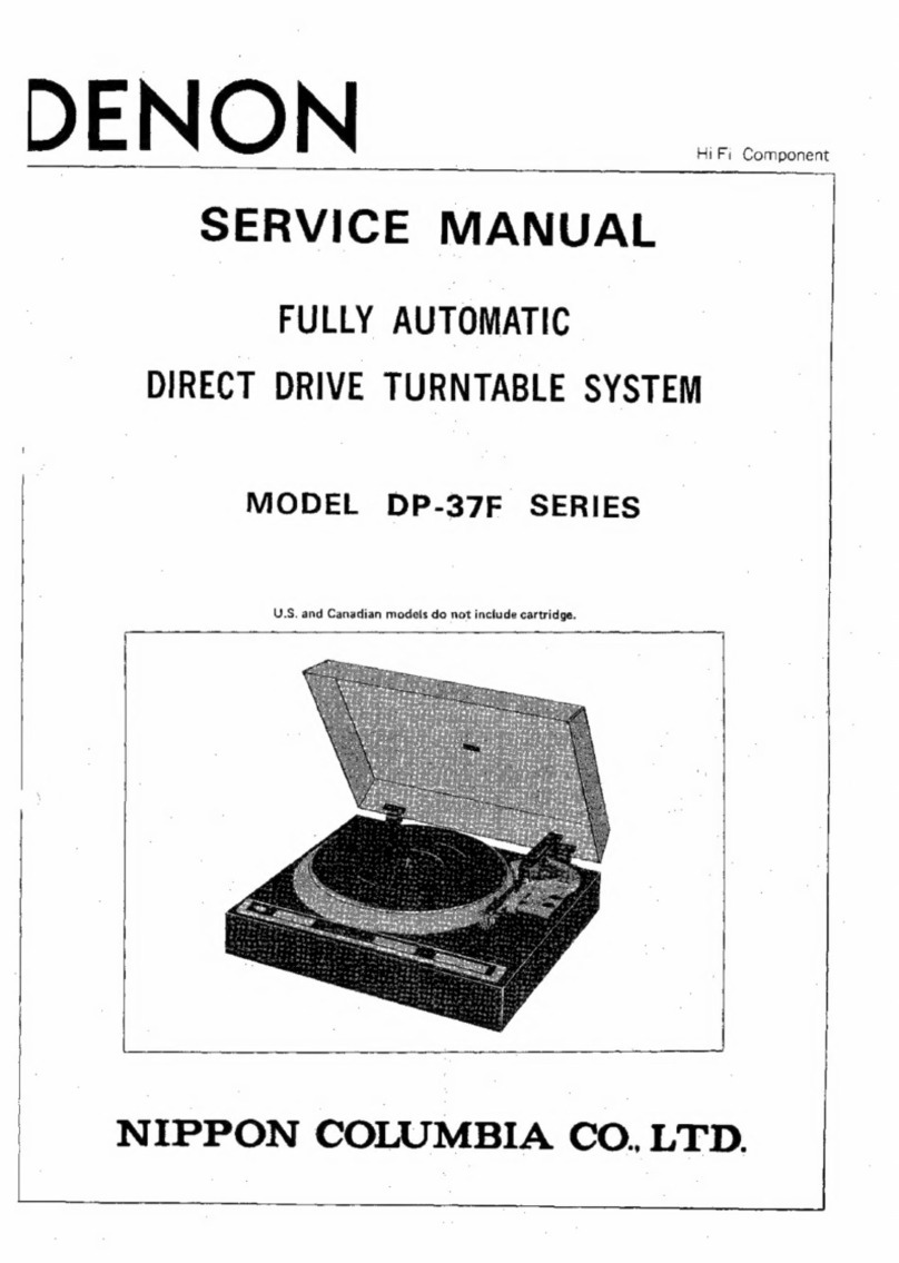
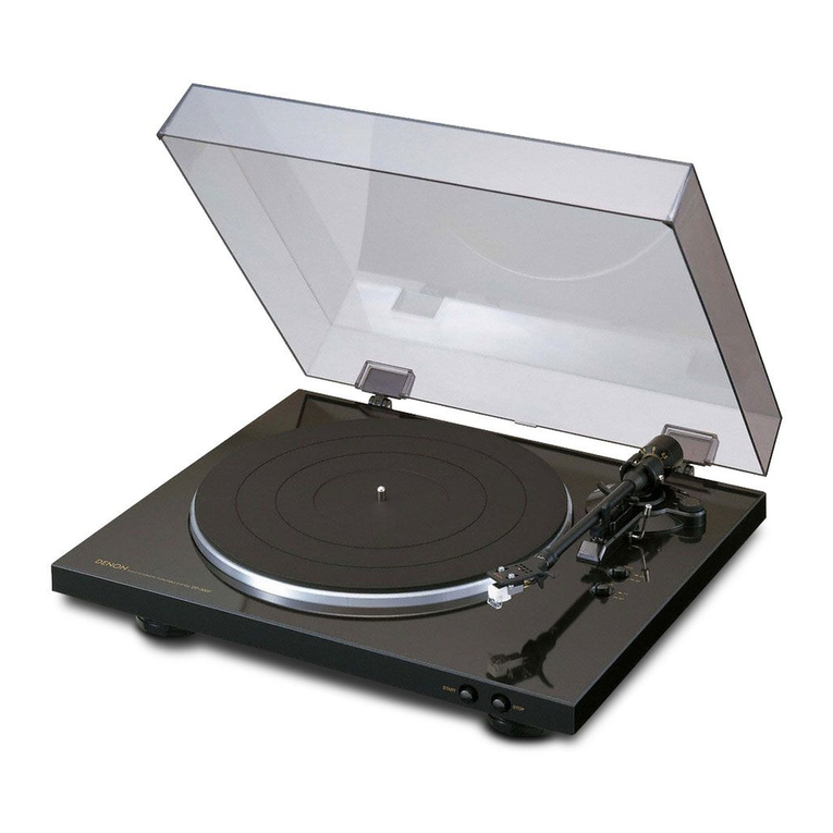
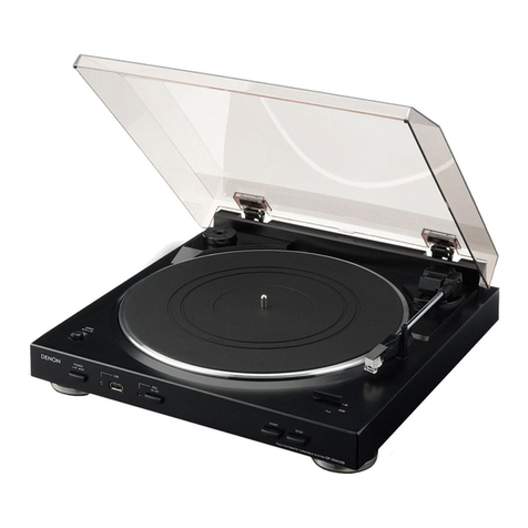
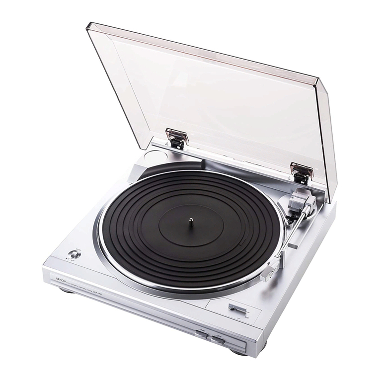
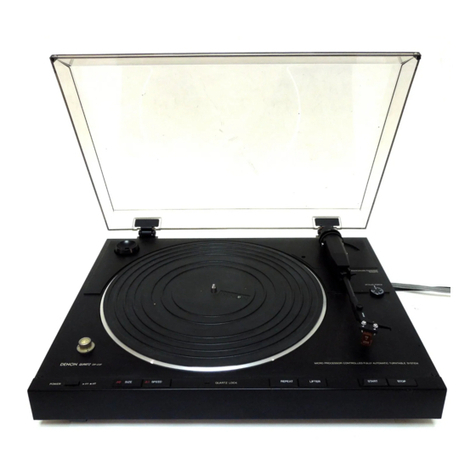
Denon DP-35F User manual

Hi
Fi
Component
DENON
~
SERVICE
MANUAL
FULLY
AUTOMATIC
se
MODEL
DP-35F/45F
SERIES.
U.S.
and
Canadian
models
do
not
include
cartridge.

FEATURES
SPECIFICATIONS
BLOCK
DIAGRAM
OF
DP-35F
>
BLOCK
DIAGRAM
OF
DP-45F
PART
NAMES
AND
FUNCTION
ADJUSTMENT
METHOD
PARTS
LIST
OF
EXPLODED
VIEW
PARTS
LIST
OF
P.W.
BOARD
SCHEMATIC
DIAGRAM
OF
DP-35F
P.W.
BOARD
OF
KU-5021
MOTOR
SERVO
UNIT
SCHEMATIC
DIAGRAM
OF
DP-45F
P.W.
BOARD
OF
KU-5020
MOTOR
SERVO
UNIT
CONNECTIONS
OF
P.W.
BOARD
FEATURES
1.
Microprocessor
controlled,
contactless
servo
tonearm
A
unigue
microprocessor
controlled,
contactless
servo
tone-
arm
ensures
safe,
easy
to
use
automatic
operation
with
no
_
deterioration
in
sound
quality.
2.
Q-damping
method
(Dynamic
servo
tracer)
Low
frequency
resonance
caused
by
the
cartridge
com-
pliance
and
the
effective
tonearm
mass
is
electronically
damped
both
horizontally
and
vertically
to
effectively
suppress
crosstalk
and
inter-modulation
distortion.
The
dynamic
servo
tracer
maximizes
the
performance
of
the
law
mass
tonearm
and
results
in
a
record
reproduction
of
excel-
lent
sound
image
with
minimum
noise
and
distortion.
3.
Low
mass
straight
arm
Having
an
outstanding
tracing
ability,
this
arm
maximizes
the
performance
of
the
high
compliance
cartridge
to
the
full
extent.
Even
with
the
most
up-to-date
high
grade
records,
its
tracing
ability
is
excellent.
4.
Location
function
(DP-45F)
Just
by
pressing
the
locate
button,
the
tonearm
is
moved
to
any
desired
location
where
the
record
play
is
started.
a
ee
er
|
a
ee
a
|
asm
meen
eee
rpees
eos
es oe
we
we
ee
wee
ee
elle
le
lk
eernrpeaeeaeeepteboaeenp
em
epeemee
s
wp
ws
@
wo
© e 8
ee
Pe
elle
el
eepeenmneaeu,
sp
epseeseneeeepespueeepereesp
B88
&
Bw
8
ee
Po
ee ee
ee
ee
Pa
a
|
EXPLODED
VIEW
OF
MAIN
PARTS
(DP-35F)
EXPLODED
VIEW
OF
MAIN
PARTS
(DP-45F)
P.W.
BOARD
OF
KU-
5014/5010
MOTOR
DRIVE
UNIT
ese
e@s
&8@
8s
@
@o@ &#&
@#@
#@
©
3
#
8&8
BD
82
@#
@
8B
6 8
5.
Record
size
detector
and
automatic
speed
selector
(DP-45F)
The
record
size
and
the
speed
are
automatically
set,
when
playing
12
inch
records
(33
1/3
rpm)
or
7
inch
records
(45
rpm)
in
the
automatic
play
mode.
The
unit
provides
a
sate-
ty
measure
which
causes
the
tonearm
to
stop
and
return
to
the
arm
rest
to
protect
the
stylus
tip
when
there
is
no
record
on
the
turntable,
even
if
the
start
button
is
pressed.
6.
DENON
quartz
on
bi-directional
servo
The
ultimate
in
rotational
accuracy
is
realized
by
the
com-
bination
of
a
magnetic
pulse
detector
and
a
quartz
lock,
with
the
addition
of
a
bi-directional
servo.
On
the
DP-45F,
with
the
utilization
of
the
bi-directional
servo
and
a
quick
response
electronic
brake,
an
even
steadier
rotational
performance
has
been
achieved.
7.
Newly
developed
cartridge
'
The
low
mass
MM
type
cartridge
DL-60
with
an
elliptically
shaped
stylus
minimizes
tracing
distortion
and
contributes
to
the
clarity
of
the
reproduced
sound.
NOTE:
U.S.
&
Canadian
models
do
not
include
cartridge.

SPECIFICATIONS
e
Phono
motor
section
Drive
system
:
Turntabie
speeds
:
Wow
&
flutter
:
S/N
ratio
=
Rise
time
:
Turntable
platter
:
Motor
:
Speed
control
system
-
Speed
deviation
:
‘Load
characteristics
:
e
Tonearm
section
Arm
type
:
Effective
length
-
Overhang
:
Tracking
error
:
Automatic
mechanism
:
Adjustable
stylus
force
range
:
Suitable
cartridge
weight
range
:
e
Cartridge
section
:
DL-60
Type:
Output
voltage
:
Frequency
response
:
Tracking
force
:
e
General
Power
supply
:
Power
consumption
:
Servo
controlled
direct
drive
33-1/3,
45
rpm
Below
0.012%
wrms
(servo
svatem)
Below
0.02%
wrms
(JIS)
-
Over
78
dB
(DIN-B)
_
Normal
speed
within
2
seconds
(at
33-1/3
ae
Aluminum
die-cast;
300
mm
diameter
Linear
drive
motor
Speed
servo
by
frequency
detection
‘a
phase
servo
control
Below
0.002%
0%
(80
g
stylus
force;
outermost
groove)
Dynamically
balanced,
straight
tube
tonearm
220
mm
16
mm
Within
3°
Electronically
controlled,
fully
automatic
0
~
3.0g
(1
scale=0.1
g)
Approximately
4.0
~
9.0
g
(including
screws,
nuts)
Moving
magnet
(MM)
2.5
mV
20
Hz
~
30
kHz
1.8+0.3g
50/60
Hz,
Voltage
is
s
shown
on
rating
label
Approx.
8W
Dimensions
:
434
(W)
x
135
(H)
x
412
(D)
mm
17
(W)
x
5.3
(H)
x
16.2
(D)
in
Weight
:
Approx.
7
kg
Approx.
15
Ib.
e
U.S.
and
Canadian
models
do
not
include
cartridge.
Above
specifications
and
outward
appearance
may
be
altered
in
future
for
improvement.
WARNING:
1.
Component
parts
a
Parts
marked
with
/\
and/or
shading
in
this
service
manual
have
special
characteristics
important
to
safety.
Be
sure
to
use
the
specified
parts
for
replacement.
2.
Leakage
current
Before
returning
the
appliance
to
customer,
test
the
leakage
current
when
the
power
plug
Is
senna
ected.
Use
a
calibrated
(with
an
error
of
not
more
than
5%)
leakage
current
tester
and
measure
the
leakage
current
from
any
exposed
metal
to
the
earth
ground.
Reverse
the
power
plug
polarity
and
test
the
above
again.
Any
current
measured
MUST
NOT
EXCEED
0.5
milliamps.
Corrective
measure
‘must
be
taken
if it
exceeds
the
limit.

~ee
BLOCK
DIAGRAM
OF
DP-35F
:
oe
ee
Rotational
speed
detection
1
Reference
voltage
Rota-
>
tion
‘control
F/V
Motor
control
microprocessor
|P/D
Magnetic
polarity
|
Xtal
a
IR3TO2
detection
Stop
control
—
: |
|
Tracking
START/STOP
command
.
einer
33/45
command
en
:
Speed
detection
Memo-
33/45
Loog)
riZe
e
Up/Down
Lolo
tart
command
ompare
(M)
;
command
|
.
-
amplif
€
50/17
=
;
Anti
skate
be
|
oO
Vertica)
motor
command
damping
(Lifter
motor)
Rest/End
START
detection
command
microprocessor,
[killer
command
IR3TO3
ont
STOP
0
Acceleration
output
Acceleration
|
input
h
,
a
a
17/30
Position
detection
)
.
|
Bone
Ty
|
ompare
—
“F
voltage
é
,
amplify
4
[
*
. )
Compara]
|
amplifier
we
ee
oe
rize
|
|
KET
o~O———»|
Memo-}
|
rize
Medpoint
detection
(=
e
¥
End
detection
|
Anti
skate
at
Reference
~
|fier
.
&
a
;
er
voltage
i
;
Horizontal
~/
motor.
(000)
—
H.Q.
damping
.
Speed
detection.

BLOCK
DIAGRAM
OF
DP-45F
Lock
indicator
rg
|
Reference
Direction
voltage
control
F/V
Rotational
speed
detection
Motor
control
P/D
microprocessor
IR3TO2
O-O—
Stop
control
=
START/STOP
command
33/45
command
Magnetic
polarity
Xtal
CO
detection
Tracking
force
adjustment
Speed
detection
33
Up/Down
Speed/Start
colnmnd
Compare
contro!
amplify
6)
49
a
Antiskate
,
ANUS
Vertical
motor
command
(Lifter
motor)
Rest/End
START
0%
[Size
Seren
comman
|
orizonta
o
Arm
control
killer
command
Stop|
Microprocessor
—
{R3TO3
STOP
0
&
Acceleration
output
Acceleration
input
mae
17/30
Position
detection
©
ss
t
Reference
Compare
T
voltage
amplify
p
&
ee
al
LIFT
o~O-——p|
Memo-
Midpoint
>
oo
>
detection
e
Wy
.
LOCATE
Locate
End
;
control
detection
P
.
<
Anti
skate
~
Horizontal
(M)
motor
(70)
H.Q.
damping
Speed
detection

PART
NAMES
AND
FUNCTION
DP-35F
1.
Power
switch
POWER
|
This
turns
the
power
supply
on
and
off.
Push
the
button
down
until
it
locks.
When
power
is
turned
on,
the
(LOCK)
indicator
will
light
up.
When
turning
the
power
off,
press
the
button
until
the
lock
is
disengaged.
Be
sure
to
return
the
tonearm
to
the
arm
rest
and
hold
it
in
with
the
clamp.
2.
Speed
selector
button
33.
START.
45
(DP-45F)
For
playing
records
manually,
press
the
button
correspond-
ing
to
the
record
speed.
33
1/3
rpm
records
(33.
Start)
45
rpm
records
(45.
Start)
In
the
automatic
play
mode,
the
switch
will
automatically
be
set
to
“33""
for
12
inch
records
and
“45”
for
7
inch
records.
3.
Lock
indicator
LOCK
The
(LOCK)
indicator
will
light
up
when
the
power
is
turn-
ed
on.
After
starting
play,
the
lamp
will
flicker
until
the
proper
turntable
speed
is
reached.
Once
the
proper
speed
has
been
attained,
the
lamp
will
stay
lit.
4.
Locate
button
<«
LOCATE
(DP-45F)
Press
this
button
to
move
the
tonearm
to
the
left,
towards
the
record
center,
to
start
the
record
at
any
desired
location.
5.
Locate
button
»
LOCATE
(DP-45F)
Press
this
button
to
move
the
tonearm
to
the
right,
away
from
the
record
center,
to
start
the
record
at
any
desired
location.
@
@66@
©
DP-45F
6.
Arm
lifter
button
UP
LIFTER
.
Press
this
button
to
raise
or
lower
the
tonearm
during
play,
or
when
playing
records
manually.
The
“UP”
indicator
will
light
up.
7.
Repeat
button
REPEAT
Press
this
button
for
playing
the
same
record
repeatedly:
the
“ON”
indicator
will
light
up.
8.
Start
button
START
Press
this
button
to
start
records
automatically.
9.
Stop
button
STOP
Press
this
button
to
stop
a
record
during
play.
10.
Size
button
SIZE
(DP-35F)
Before
playing
a
record,
press
the
button
corresponding
to
its
record
size.
|
For
30
cm
(12
inch)
records,
the
(30)
indicator
will
light.-
For
17
cm
(7
inch)
records,
the
(17)
indicator
will
light.
11.
Speed
button
(DP-35
SPEED)
Before
playing
a
record,
press
the
button
corresponding
its
record
speed.
The
(33)
indicator
will
light
for
33
1/3
rpm
records.
The
(45)
indicator
will
light
for
45
rpm
records.
to
12.
Stylus
force
adjustment
knob
STYLUS
FORCE
This
is
used
to
adjust
the
stylus
force.
13.
Q-damping
adjustment
knob
Q-DAMPING

ADJUSTMENT
METHOD
e
PHONO
MOTOR
ADJUSTMENT
1.
Off-set
adjustment
1)
2)
3)
4)
5)
6)
7)
8)
Stats
2)
3)
4)
Set
the
X-axis
and
Y-axis
sensitivity
of
the
oscilloscope
to
100mV/cm
by
using
a
10:1
probe.
Connect
the
X-axis
terminal
of
the
probe
with
TP-203
on
the
motor
drive
base
board
and
the
Y-axis
terminal
of
the
probe
with
TP-204.
Use
pin
No.
8
as
the
ground.
Connect
pin
No.
5
and
pin
No.
8
and
make
a
low
_
resistance
circuit
on
the
input
terminal.
Stop
the
rotor
at
the
maximum
position
of
the
X-axis
amplitude
of
the
Lissajous’
figure
of
the
oscilloscope
while
turning
the
motor
by
hand.
Set
the
maximum
amplitude
at
the
we
-axis
by
adjusting
VR-201.
A=A'
Stop
the
rotor
at
the
maximum
position
of
the
Y-axis
amplitude
of
the
Lissajous’
figure.
|
Set
the
maximum
amplitude
at
the
Y-axis
by
adjusting
VR-202.
B
=
B’
Adjust
the
center
of
the
circle
to
t
50mV.
Y-axis
1
(100mvV)
1
(100mV)
X-axis
Check
the
X-axis
and
Y-axis
sensitivity
of
the
oscillo-
scope
by
using
+
5V
power
supply.
In
case
of
DP-45F,
cover
the
photo
transistor
of
the
size
detecting
light
receiver
with
a
black
rubber
sheet
or
something
to
avoid
that
light
enters.
Remove
the
arm
from
the
arm
rest
and
remove
the
turntable.
Then,
turn
the
motor
with
full
speed.
Set
the
amplitude
of
the
X-axis
and
Y-axis
of
the
Lissajous’
figure
to
15
VP-P
by
adjusting
VR-203
and
VR-204.
Make
sure
that
there
isno
voltage
difference
between
the
X-axis
and
the
Y-axis.
4.
5.
Hereafter,
3.
Center
adjustment
1)
Adjust
the
X-axis
and
Y-axis
sensitivity
of
the
oscillo-
scope
to
2V/cm.
2)
Set
the
amplitude
of
the
X-axis
and
Y-axis
of
the
Lissajous’
figure
to
exactly
the
same
point
from
the
center
by
adjusting
VR-205
and
VR-206.
After
the
adjustment,
the
amplitude
should
be
as
shown
in
the
figure
below.
Figure
7,.6V+0.4V
Adjusting
the
head
gap
Adjust,
so
that
the
gap
between
the
turntable
magnetic
-
coating
surface
and
the
detection
head
is
0.18
mm.
Lock
adjustments
for
45
rpm
__
the
earth
reference
point
of
the
measuring
instrument
should
be
connected
to
wrapping
terminal
35.
of
the
servo
control
circuit
board.
|
1)
2)
3)
4)
Connect
the
two-channel
oscilloscope
to
TP-
1
aid
|
TP-2.
Set
the
speed
selector
to
45
rpm.
Take
the
arm
off
the
arm
rest
and
move
it
toward
he
turntable
to
rotate
the
phonomotor.
Adjust
VR-1
so
that
the
pulse
from’
‘TP-
1
is
positioned
~
to
50%
of
the
triangular
wave
length
from
T.P.2.
0
|
50%
100%
|
6.
Lock
adjustments
for
33
rpm
1)
Connect
the
oscilloscope
in
the
same
manner
as
the
45
rpm
lock
adjustments.
Set
the
speed
selector
to
33°
rpm.
2)
Make
sure
that
the
srisliea
sues
is
poatisned
be-
tween
40%
and
80%
of
the
triangular
wave
length.
NOTE:
Phase
lock
position
for
33
rpm
is
fixed
(relative
to
45
rpm)
by
R12
(metal
fiim
resistor).
:
—~6§—

®
ADJUSTING
THE
ARM
CONTROL
SECTION
Lead-in
adjustment
hole
VR-5
(Tracking
force
adjustment)
VR*3
(Horizontal
offset
voltage
adjustment)
VR+4
(Lifter
offset
voltage
adjustment)
mad
1)
2)
3)
1)
2)
3)
1)
2)
3)
4)
Adjusting
the
horizontal
OP
amp.
offset
voltage
Fix
the
tonearm
to
the
arm
rest
and
connect
the
oscil-
loscope
to
TP-8.
Set
the
lifter
switch
to
the
UP
condition.
Turn
VR~3
and
adjust
to
OV+0.01V.
Adjusting
the
lifter
OP
amp.
offset
voltage
Fix
the
tonearm
to
the
arm
rest
and
connect
the
oscil-
loscope
to
TP-6.
Set
the
lifter
switch
to
the
DOWN
condition.
After
about
7
seconds,
adjust
to
OV+0.01V
by
turning
VR-4.
Adjusting
the
tracking
force
Turn
the
power
supply
switch
OFF.
Take
the
arm
off
the
arm
rest.
Rotate
the
balance
weight
so
that
the
tonearm
becomes
parallel
to
the
turntable
surface
when
let
go.
Return
the
arm
to
the
arm
rest
and
turn
the
power
supply
switch
ON.
(Note)
In
case
of
DP-45F,
cover
the
size
detecting
photo
transistors
(2
pieces)
with
a
rubber
sheet
or
something
to
avoid
that
light
enters.
Wait
seven
seconds
after
the
arm
has
towered.
Place
the
cartridge
stylus
tip
onto
a
stylus
force
gauge
and
set
the
stylus,
force
adjustment
knob
to
1.5g.
(Note)
At
this
time,
the
stylus
tip
height
should
be
adjusted
so
that
it
is
about
the
same
height
as
during
play.
Turn
VR-5
and
adjust,
so
‘that
the
stylus
force
gauge
reads
1.5
g.
(Turn
VR
slowly.)
A.
Adjusting
the
30
cm
lead-in
position
Place
a
30
cm
record
on
the
turntable
and
set
the
record
size
selector
switch
to
“30”.
(Note)
Keep
the
bottom
cover
closed.
Move
the
arm
so
that
the
stylus
tip
is
at
approximately
the
30
cm
lead-in
position.
Insert
a
small
flat-headed
screwdriver
into
the
lead-in
adjustment
hole;
move
the
arm
back
and
forth
and
fit
the
screw
driver
into
the
groove
of
the
cam
inside
gently.
3)
5.
After
turning
the
screwdriver,
pull
it
out
once.
Press
the
start
switch
and
adjust
so
that
the
stylus
position
stops
at
the
30
cm
lead-in
position.
(Note)
The
30
cm
lead-in
adjustments
cannot
be
per-
formed
unless
the
stylus
tip
position
is
approximately
in
the
30
cm
lead-in
position.
In
addition,
if
the
screw-
driver
is
left
inserted,
the
arm
will
not
move.
Adjusting
the
17
cm
lead-in
position
|
Adjust
as
necessary,
such
as
when
parts
of
the
sensor
sec-
tion
have
been
replaced.
However,
the
following
procedures
should
only
be
ee
when
a
discrepancy
is
found
for
the
17
cm
lead-in
position,
after
the
30
cm
lead-in
position
has
been
adjusted.
1)
2)
3)
4)
5)
6)
Stopper
Set
the
record
size
selector
to
17
cm.
(Note}
In
case
of
DP-45F,
the
size
is
automatically
changed
by
placing
a
17
cm
record
on
the
turntable.
By
continuously
pressing
the
start
switch,
the
arm
will
move
over
and
stop.
At
this
time,
check
now
many
millimeters,
toward
the
inside
or
outside,
the
stylus
tip
deviates
from
the
required
17
cm
lead-in
position.
Take
off
the
bottom
cover
of
the
cabinet
and
check
the
adjustment
scale
position
of
the
shutter.
(One
adjustment
scale
corresponds
to
a
stylus
tip
movement
of
0.5
mm.)
Untighten
the
screw
holding
the
sub
shutter
and
place
a
small
flat-headed
screwdriver
into
the
slot
of
the
shutter.
When
the
stylus
position
is
toward
the
inside,
compared
to
the
required
position,
move
the
sub
shutter
toward
the
right
of
the
scale;
when
the
stylus
position
is
toward
the
outside,
move
the
sub
shutter
toward
the
left.
When
completed,
tentatively
tighten
the
screw
holding
the
sub
shutter.
After
the
adjustments
are
made,
press
the
start
switch
and
check
whether
or
not
the
stylus
stops
at
the
17
cm
lead-in
position.
If
the
stylus
stops
at
the
required
position,
then
tighten
the
sub
shutter
screw.
Screwdriver
_
Shutter
Sub
shutter
Sub
shutter
screw
Slot

|
PARTS
LIST
OF
EXPLODED
VIEW
|
(eee
eee
eee
4713303045
4711303018
4751003006
4438545201
4638225004
4711810019
4338241100
3418025205
4761003009
4751005004
3158451003
4248019202
4730811002
4733808012
2398013215
4338175108
3158712108
4744304000
4730306012
4428030108
1128085003
1128085029
4756133007
3158896202
3158899005
oon
oa
kh
WN
=
3158553024
DL-0060
4713808003
4731808001
4731806003
|
2178081027
KU-5021*1
KU-5020*1
KU-5021*3
KU-5020*3
4730355018
4730305013
4418846014
4418814509
3918423006
3918425004
4700009019
KU-50206
1468150504
1468150517
4732309017
4218217209
4218358003
4218288005
4218361003
4730356033
4733810000
1058091303
4751106042
1048079102
2178081030
|
3x6
CBS
3x6
CPS
3W
|
COLLER
SPRING
2x3
CPS
—
SHUTTER
MAGNET
ASS'Y
3E
RING
4W
FRICTION
WASHER
ADJUST
CAM
3x12
CBTS
(2)
3x12
CBTS
(1)
COIL
ASS’Y
YOKE
(A)
ASS'Y
LATERAL
WEIGHT
3x3
BSS
(D)
3x12
CBRTS
(1)
VOLUME
BRACKET
VOLUME
KNOB
VOLUME
KNOB
14N
TONE
ARM
ASS'Y
BALANCE
WEIGHT
‘ASS'Y
HEAD
SHELL
ASS’Y
PICK
UP
CARTRIDGE
|
3x25
CBS
3x12
CPTS
(2)
3x20
CPTS
(1)
MOTOR
ASS’‘Y
MOTOR
ASS‘Y
OUTPUT
P.C.B.
OUTPUT
P.C.B.
LEAD
IN
LED
P.C.B.
LEAD
iN
LED
P.C.B.
|
3x10
CBRTS
3x10
CBRTS
(1)
WASHER
HEAD
SUPPORT
MAGNETIC
HEAD
MAGNETIC
HEAD
ASS'Y
3x6
CPS.
W
P.C.B.
SUPPORT
FRAME
|
FRAME
3x16
CFTS
(1)
REC.
TURNTABLE
REC.
TURNTABLE
RUBBER
SHEET
RUBBER
SHEET
3x12
CRTS
(2)
2.6x12
CBRTS
(1)
BOTTOM
COVER
WASHER
INSULATOR
ASS'Y
E2,EP,E1,
EA,EG,EK
DP-35F
DP-45F
DP-35F
DP-45F
DP-35F
DP-45F
DP-35F
DP-45F
DP-35F
DP-45F
E2,EA,EU,
EC,
EK,
EG
Ei,
i
47
48
49
50
51
52
54
55
56
57
-58
59
60
67
68
69
70
71
72
73
74
75
76
78
79
80
4638631
203
KU-5021
KU-5020
KU-5021*7
KU-5020*7
KU-5021*8
KU-5020*8
1138161302
1138162110
1138162107
4438158067
4438158096
4620027003
1298010005
1038232108
1038232111
1018376314
4730308010
1038229409
1038233107
1038230401
1468151008
4628023009
4018041015
EP-7376
2033642103
2031640000
4338243001
4730460013
4733811009
KU-5020*4
4730356017
4318086000
KU-5020*5
3158911103
4418314009
4498066209
3939220000
1468153103
|
47
33812008
‘4428092007
4730204017
4730253013
SPRING
SERVO
CONTROL
UNIT
SERVO
CONTROL
UNIT
POWER
SW
P.C.B.
POWER
SW
P.C.B.
LOCK
LED
P.C.B.
LOCK
LED
P.C.B.
BUTTON
(A)
BUTTON
(B)
BUTTON
(B)
COLLAR
COLLAR
RUBBER
BUSH
CUSHION
RUBBER
CABINET
CABINET
CABINET
ASS‘'Y
3x14
CBRTS
(1)
FRONT
PANEL
SUB
PANEL
SUB
PANEL
DUST
COVER
ASS‘'Y
BUSHING
HINGE
BOS
Sie
Nes
ae
CORD
BUSH
OUTPUT
CORD
ASS'Y
OUTPUT
CORD
ASS'Y
SUB
SHUTTER
4x20
CBRTS
(2)
3x25
CBRTS
(2)
SIZE
DET.
P.C.B.
3x12
CBRTS
(2)
FRICTION
SHEET
SIZE
DET.
P.C.B
ARM
REST
ASS'Y
.
BUSH
PLATE
LED
STAND
LED
WITH
WIRE
LED
COVER
3x12
CBTS
(1)
SELECTOR
BRACKET
2.6x8
CRTS
(1)
2.6x6
CBRTS
DP-35F
DP-45F
DP-35F
DP-45F
DP-35F
DP-45F
DP-35F
DP-45F
DP-35F
DP-45F
DP-35F
DP-45F
E2,EC,EU,
EA,EG,EK
EP.E1
DP-45F
DP-45F
DP-45F
DP-35F
DP-45F
EU
only
DP-35F
DP-45F

PARTS
LIST
OF
P.W.
BOARD
KU-5020
SERVO
CONTROL
UNIT
(DP-45F)
‘|
SEMICONDUCTOR
GROUP
|
iC1
iC2
1C4
1C3,5
2630257001}
M5218P
80
|
IC6
2630198005|
NJM4556
C9,
24,27
|
2544136001
|
CE4wW1C101=
1C12
2630147001|
uPC78M05H
50,
68
|
C13
2630160004;
uPC7905H
C3,
10
2544146004
|
CE4W1H010=
IC7
2620276005
|
HD14066BP
12,17,
18
,
20,
66,
67
IC9,
10
2620218005|
HD7403P
ic11
2620057004
|
HD7473P
a
a
TR1,2
2710102005]
2SA1015
(Y)
35,
36
2544086009
|
CEOQ4W1E222=
C64
2544019005
|
CE04wW1C221=
8,18,
19
: 7
ae
|
|
c19
2551070008
TR4~7
2730198002}
2SC
1815
{Y)
008
|
CQ93M1H682K
9~17
|
|
seas
?
|
TR3
2740038002
2SD467
(Cc)
aS
earls
ee
D7
~
10
2760237001
|
RVO06
Daas
Bach
es
es
Di~6
2760049008
|
1S2076
OJeNiesS:
11
~
38
TH1
LEDG,
9,10
|
3939041001|
LED
(LN81RCP-HL)
LED3~5
3939213004|
LED
(GL-5EG23)
TP1,2
3939157005|
TPS605
LED1
-
CD1,2
CD3
2630173004
2630174003
2630237005
2760311008
3939185006
3939053002
3939053028
RESISTOR
GROUP
CAPACITOR
GROUP
7
;
C39,
40
70,
73
77,78
84
~
86
C14
C57
C25,
26,
29
30,
33,
34
37,41,
56
58,
61,
62
79
C7,8
C46
1,2,
11
13,
65
C21,
22
C6,
23
28,
31,
32
38,
45,
47
2452195008
2452201002
2452215001
2452223006
EP-5462H15
|
2116000073
2118024015
2531004007
2531008003
2531024003
2531027000
2533619005
2533627000
2533637003
2544129005
|
2544132005
IR3TO2
IR3TO3
LAG6358
THERMISTER
(1KQ)
LED
(NLO202GP3)
CDS
CDS
RN14K2E332G
RN14K2E562G
RN14K2E223G
RN14K2E473G
SOLID
VOLUME
VO8PB203
V16V20KB502
CK45B1H102K
|
CK45B1H472K
CK45F1H1032Z
CK45F1H104Z
CC45SL1H470J
CC45SL1H101J
CC45SL1H271J
CE04W1A470=
CE04W1C0100=
Metal
film
3.3KQ
5.6KQ
22KQ
4A7KQ
Volume
22KQ2
20KQ
-
5KQ
YaW
“AW
YaW
%W
Ceramic
1000PF
50V
A700PFE
50V.
0.01uF
50V
0.1uF
50V.
48,51,
53
87
C63,
69
2544135002
|
CEO4W1C470=
2551078000
2554194017
C60
C15
CQ93M1
H333K
CO93P1H473J
OTHER
PARTS
GROUP
4178028101
4428030108
3998025000
2129180003
2129218001
4438568107
2050158049
HEAT
SINK
VOLUME
BRACKET
CRYSTAL
(4.5MHZ)
PUSH
SWITCH
PUSH
SWITCH
LED
HOLDER
4P
WRAPPING
TERMINAL
3P
WRAPPING
TERMINAL
2050158036
220uF
Remark
Electrolytic.
47pLF
16V
100uF
16V
1
uF
50V
2200uF
25V
16V
Film
-0.0068uF
50V
0.01uF
50V
|
0.018uF
50V
0.047uF
50V
0.033uF
50V
0,047uF
50V
e@
The
carbon
resistors
rated
at
%4W
are
not
listed
herein.

KU-5021
SERVO
CONTROL
UNIT
(DP-35F)
fs
ee
SEMICONDUCTOR
GROUP
1C7
2620276005
HD14066BP
1C8,11
262005
7004
HD7473P
1C1
26301
73004
IR3TO2
IC2
2630174003
IR3TO3
1C4
2630237005
LA6358
1C3,5
263025
7001.|
M5218P
IC6
2630198005
NJM4556
1C12
2630147001
uPC78M05H
IC13
2630160004
|
wPC7905H
TR1,2,22
|
2710102005
2SA1015
(Y)
TR4~7
2730198002
2SC1815
(Y)
9~11,16,17
19
~
21
TR3
2740038002
2SD467
(C)
D1,4~6,
2760049008
182076
11
~
13
16,17
36
~
38
D7
~
10
2760237001
RV06
|
TH1
276031
1008
THERMISTER
(1KQ)
LED.3~5
|
3939213004
LED
(GL-5EG23)
GREEN
7,8
|
LED1
3939185006
LED
(LNO202GP3)
LED6,9,10
|
3939041001
LED
(LN81RCP
(HL))}
RED
CD1
3939053028
CDS
(10-15KQ)
CD2,
3
3939053002
|
CDS
RESISTOR
GROUP
Metal
film
R20
2452195008
RN14K2E332G
3.3KQ2
%W
R19
2452201002
RN14K2E562G
56KQ
%WwW
R12
2452215001
RN14K2E223G
22K
YW
R11
2452223006
RN14K2E473G
—
47KQ
YW
Variable
—
resistor
VR1
EP-5462H15
SOLID
VOLUME
22KQ
VR3~5
2116000073
VO08PB203
20KQ
VR6,
7
2118024015
V16V20KB502
5KQ
Ceramic
C39,
40
2531004007
CK45B1H102K
1000PF
50V
C14
2531008003
CK45B1H472K
4700PF
50V
C25,26,29
|
2531027000
CK45F
1H104Z
O.1uF
50V
30,33,34
|
.
37
41
C7,8
|
2533619005
CC45SL1H470J
47PF
50V
C42,
46
2533627000
CC45SL1H101J
100PF
50V
C11,13,43
|
2533637003
CC45SL1H271J.
270PF
50V
|
i
Electrolytic
C21,
22
2544129005
CE04W1A470=
47
uF
10V
C6,23,28
2544132005
CE04W1C100=
10uF
16V
31,32,38
45,48,53
C63,
69
'
2544135002
CE04W1C470=
47
uF
16V
C9,
24
2544136001
CE04W1C101=
100uF
16V
27,50
ae
|
eee
|
Remarks
2544146004
CE04W1H010=
1uF
50V
2544147003
2542037005
2542038004
CE04W1H2R2=
CE02W1E102=
CE02W1E222=
2.2uF
50V
1000uF
25V
2200uF
25V
Film
0.0068uF
.
50V
0.014F
50V
2551070008
CQ93M1H682K
2551072006
CQ93M1H103K
0.018uF
50V
0.033uF
50V
CQ93M1H183K
CQ93M1H333K
2551122008
|
CQ93M1H473J
0.047uF
50V
2554194017
|
CQ93P1H473J
0.047uF
50V
__
OTHER
PARTS
GROUP
|
4178028101
HEAT
SINK
4428030001
VOLUME
BRACKET
3998025000
CRYSTAL
(4.5
MHZ)
2129180003
PUSH
SWITCH
2129218001
PUSH
SWITCH
4438568107
LED
HOLDER
2551075003
2551078000
*
The
carbon
resistors
rated
at
%W
are
not
listed
herein.
4
KU-5010/5014
MOTOR
DRIVE
UNIT
SEMICONDUCTOR
GROUP
2630257001
M5218P
H201,
202
|
2680042004
H-300A
TR202,204
|}
2710105002
|
2SA966
(Y)
_TR201,
203}
2730201009
|
2SC2236
(Y)
D201,
203
|
2760049008
182076
TH201
,202
|
2760311008
|
THERMISTOR
(1KQ)
RESISTOR
GROUP
~
VO8PB
102
(1K&2)
V0O8PB203
(20K22)
ORG,
PINK
:
VR203,204
|
2116000031
VR201,
202]
2116000073
205,
206
CAPACITOR
GROUP
2531027000
|
CK45F1H104Z
O.1uF
SOV
2544015009
;
CE04W1C100=
10uF
16V
C203,
204
|
2551072006
|
CO93M1H103K
0.01uF
50V
.@
The
carbon
resistors
rated
at
%W
are
not
listed
herein.
PACKING
AND
ACCESSORIES
GROUP
Ref.
5038044101
|
PACKING
ASS'Y
5038045100
|
PACKING
(L)
5038046109
|
PACKING
(R)
5298006002
|
45
ADAPTOR
5118243000
|
INSTRUCTION
MANUAL
2033667007
|
PLUG
ADAPTOR
EP,
£1
3158547001
|
SHELL
ACCESSORY
ASS'Y|
EU,
EC
5018280338
|
CARTON
CASE
ASS'Y
DP-35F
5018280325
|
CARTON
CASE
ASS'Y
DP-45F
5018281133
|
CARTON
CASE
DP-35F
5018281120
|
CARTON
CASE
DP-45F
5028103007
|
BOTTOM
PLATE
5028104006
|
PROTECTION
PLATE
5028102105
|
UPPER
PLATE
5058006006
|
ENVELOPE
Remarks
60x100

EXPLODED
VIEW
OF
MAIN
PARTS
|(DP-35F)
en

B
EXPLODED
VIEW
OF
MAIN
PARTS
(DP-45F)
)
/
vanes,
5
A
?
~
By
=
f
a
(3
¢3
|
\\
;
/
12>

SCHEMATIC
DIAGRAM
OF
DP-35F
33
SPEED
45
30
SIZE
17
START
STOP
REP.
LIFT
A
B
C
D
|
E
F
G
H
|
FG-30I
(KU-5014)
LAG358
i
:
|
R211
c203
|
TReol
M5218P
'
LOCK
IND.
GND
=
LED
I
LNO2O2GP3
R2!
Cis
NJM4556
22k
0,0068
wee
VR204
Ik
Europe/Australia
R203
330k
MOTOR
IC
|
CONTROL
IR3TO2
HEAD
—-
pPC78MOSH
yPC7905H
es
F
WY
WM
132
(32
IN
5
OUT
com
OUT
COM
IN
TH20I,
202
TO5-C2i0D
VR203
Ik
‘
1
a
a
AL
i
R15!
10k
MULTI.
VOLTAGE
330k
65
Ril
VRI
22kB
JRI
2SA966
(Y)
28A1015
(Y)
28C1815(Y)
2302236
(Y)
28D467
(C)
TR201,203
TR202,204
2SA966(Y)
2SC2236(Y)
10
O
“av
elev
(-10V)
(+410V)
10
D7~10
.
ic
12
RVOG
x4
i
ec
yPC78MOSH
>——I
power
sw
NORTH
AMERICAN
Laon
a
E(
zie)
e
C
IN
DRIVE
OUT
\
DOWN
TIME
T/T
ORIVE
x
|
220
|TRI6
ae,
ae
WHT
Slo
(fesciaisty)
@
STOP
ARM
CONTROL
op
SwOD
/A\
POWER
TRANS
we
fad
Yo}
}
:
Oo”
Oo—
B
TOS
IC2
IR3TOS
Vt
So0sH
IS2076
ee
z
()
“aer-7
LIFTER_-
RETURN
CONT.
:
a
-—
MATCHING
|
REST
END
CONT
H.
ae
ACCIN
{IN
ACCOUT}
END
|
ANTI.
DRIVE
+C45_
C53,
;
22},
MAX
10/16
10/16
Ne
x
Ee
|
DAMPING
£
ce
MIN
a
MIN
+
fog
DIG
D36
DI7
gel
TRACKING
FORCE
xam
§=&
ANTI-SKATING
VR4
20k
one
(M)
ARM
UP/DOWN
R67
C58
22
0.1
GNO
20
LED9,10
26
LN8@IRCPHL
R86
47k
CDS
|
INSIDE
—DARK
KU-502
|
OUTSIDE-LIGHT
|
CDS
2
REST
END
LED6
LN8IRCPHL
CDS
3
30/17
IN
SIDE
+5V
OUT
SIDE
-—5V
@-+
HORIZONTAL
MOTOR
10
+@
LED3,4,5,7,8
Ics
D1,4~6,1
ic3
i¢4
_.
C5
Ic6
=
ic?
"ALTERNATIVES
:
For
2SAIOI5(Y)
:
2SA999(E/F)
Note:
e
Resistance
shall
be
1/4W
unless
otherwise
specified
and
the
GL-5EG23
HD7473P
1$2076
M5218P
LA6358
M52i8P
NUM4556
HDI4066
BP
For
2SCI8IS(Y)
:
28C2603(E/F)
esate,
The
unit
of
capacitor
is
uF,
P
is
pF
unless
otherwise
specified.
This
circuit
diagram
shows
the
basic
circuit.
It
is
subject
to
change
for
the
purpose
of
improvement.
Parts
marked
with
Z\
are
of
importance
in
respect
to
the
safety,
use
the
specified
type
without
fail,
a
ce
P

P.W.
BOARD
OF
KU-5021
MOTOR
SERVO
UNIT
7
-502-7
KU
Pees
ie
N
©
ny
>
x
SAA.

SCHEMATIC
DIAGRAM
OF
DP-45F
A
B
C
D
|
£
F
G
H
_&
oe
Eee
6
eee
@
eee
—-
See
«=
ees
-=
|
2s
eEeweeeee
ee
er
=
2
=
GEESE
=
eee
ne
=o
eee
2
eee
©
a8
ae
|
FG-300
_
enone
,
;
|
LOCK
IND,
a
"
(KU-5010)
ae
ze
sul
.
:
Rail
c203.
|
TR2Ol
“beaiee
q
|
|
HSMASSE
alee
t
4
5
R204
HEAD
ot
Is
Europe/Australia
MOTOR
CONTROL
IC
|
IRSTO]
yPC7BMOSH
—yPC7905H
POF
ROG
YM
START
STOP
SAMP.
REVOLUTION
|
PULSE
DET
132
‘
$73
2
t
ouT
com
OUT
VR201
20k
z
Cc)
3S
le
OQ
z
7
ne
H202
.<
H-Z008I
1]
15k.
3
di
:
AAA,
:
4
ee
TH203tk
TDS~C2I00
7
;
-
TR201,
203
TR202,
204
*
diate,
28C2236(Y)
2SA96G(Y).
-
0
Aue
4g
©
;
GND
Netovy
Aeiovh,
45
'
a
.
:
=
com
IN
_
TR3
{
ae
ok
a
2SD467
MULTI.
VOLTAGE...
ae
;
y
28A966
(Y)
gy
28A1015
(Y)
:
2801815
(Y)
2802236(Y)
280467
(C)
Lal
>,
“CE
nen
:
Se
AD
RS
ST
0
ism
Cc
3
|
ages
|
;
|
|
ac
)
FE:
lOOk
se
|
asc
Wi
get
ee
«He
.
lene
seas
7
er
NORTH
AMERICAN
gies
RVO6
x4
O
AN
1
CC
suas)
3
|
Terp
Ay”
)scisis
_4y")
07
Sw9a
POWER
SW
one
ee
EC
2:48)
ee
inane
628
,
:
O
:
“Steer
|
smarts
as
|
|
“A
aes
eed
ee
A
!
AC
IN
STOP
:
3
ap
|
4
te
|
Sects
ARM
CONTROL
“Sve
3
|
IC2
-
IR3TO3
SuB
G
C13
ie
:
RVO6
Me
:
,
19
7
:
:
av-—7
OUTSIDE
[se
Y
ee
me:
wv
Cla
;
—
UP/DOWN
az
Z
os
SK_I
TRI3
a
:
oe
|
:
TP!
eee
30/17
POSITION
‘DETECT
ANTI
.H.
DRIVE
J.
——
:
oer
TPS6OS
4
pie
per
R14
—&
|
{
RSS,
INSIDE
A43
-
: :
a
O)
MAX
.
:
Se
ee
ee
g
ie
V.
MOTOR
DRIVE
a
es
“my
TP2
mars
TPS605
9
re
c52
O
MINS
:
8
=
|
TRACKING
FoRcE
S
wax
&
ANTI-SKATING
,
8
DOWN
UP
|
TRIG
:
ae
g
)
40
(M)
ae
2scisis(y)
’
mn
>
NV.
LED?
:
:
RI26
5
te)
OES
|
VLT
GL-5HD23
REP.
i
:
eerlisieun
|
gy]
;
i
Ses
1
Ce
Cie
eS
ee
ee
eee
TY20"
REESE
OE
eee:
Samara
Ohl
ae
sé
aes
2
a
|
|
tHSInCPHE
“iw
19
2k
at
CDS!
INSIDE
—
DARK
OUTSIDE-LIGHT
LIFT
'
UPIL
4
.
:
DWN:
H
.
CDS2
REST/END
CDS3
30/I7
;
x
|
ROI
;
“4
>
o
0
MIO-
POINT
O
INSIDE
+5V
|
Peta
+
f
Ph
ee
at
ey
IcLR
Vee
2CLR
SG
HORIZONTAL
swe
pS
(M)
6
MOTOR
O
30)
+S
-5V
Ct
ae
ee
Bee
ea
GND
—
°
OG,
1~25
ICD
Icio
AC
HI
1¢3_
1¢4
ics
tic6
ss
C7
ALTERNATIVES
+
For
2SAI0IS(Y)
+
2SA999(E/F)
Note:
e
Resistance
shall
be
1/4W
unless
otherwise
specified
and
the
1S2076
HD7403
HD7403
HO7473
M5218P
LA6358
M5218P
NJM4556
HD
I40668P
For
2SCIBIS(Y)
=
2SC2603IE/F)
ecg
,
:
Vss
e
The
unit
of
capacitor
is
uF,
P
is
pF
unless
otherwise
specified.
This
circuit
diagram
shows
the
basic
circuit.
It
is
subject
to
chanae
for
the
purpose
of
improvement.
®@
Parts
marked
with
Z\
are
of
importance
in
respect
to
the
safety,
use
the
specified
type
without
fail.
—
15
—

=
2
a
O
>
om
Lu
“”
as
O
-
O
=
©
N
©
ns
—
=
Li.
O
Q
aa
<x
O
a
=
a.
7
-502-
KU
8
-502-
KU
—-
16
—

CONNECTIONS
OF
P.W.
BOARD
pon
nom
eerinansnte
banned
ab
MAA
ail
ib
dtm
oP-45e
POWER
SW
©
KkU-502-
KU-5020
KU-S@2tes
de
|
POWER
ones
DP-45F
ONLY
te
Y
DP-45F
ONLY
®

/P.W.
BOARD
OF
KU-5010/5014
MOTOR
DRIVE
UNIT
eee
fo
eee
—
ann
Other manuals for DP-35F
1
This manual suits for next models
1
Table of contents
Other Denon Turntable manuals

Denon
Denon DP-200USB User manual

Denon
Denon SC5000M Prime User manual

Denon
Denon DP-200USB User manual

Denon
Denon DP-29F User manual

Denon
Denon DP-3000NE User manual

Denon
Denon DP-300F User manual
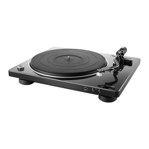
Denon
Denon DP-37F User manual
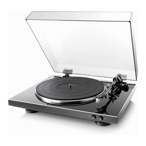
Denon
Denon DP DP-300F User manual
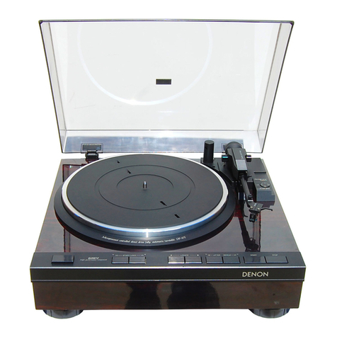
Denon
Denon DP-200USB User manual
Denon
Denon DP-6700 User manual