2
103907
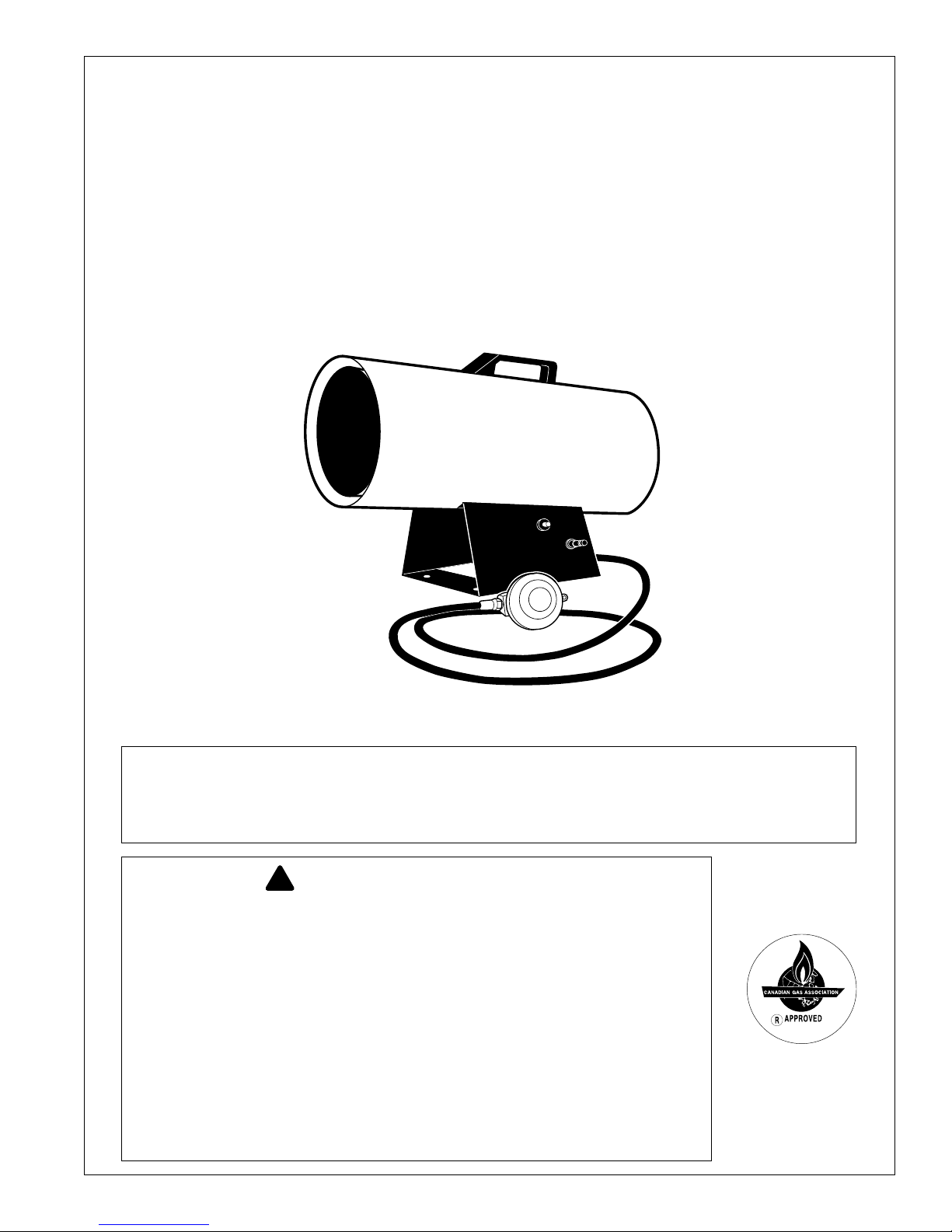
35,000 BTU/Hr CANADIAN
PROPANE CONSTRUCTION HEATER
these signs, the heater may not be working
properly. Get fresh air at once! Check for
proper ventilation and have heater serviced
Propane Gas: Propane gas is odorless. An
odor-makingagent is addedto propane gas.
The odor helps you detect a propane gas
leak. However, the odor added to propane
gas may fade. Propane gas may be present
even though no odor exists.
Make certain you read and understand all
warnings.Keepthismanualforreference.It
isyourguidetosafeandproperoperationof
this heater.
• Install and use heater with care. Follow
all local ordinances and codes. In the
absence of local ordinances and codes,
refer to the Standard for Storage and
Handling of Liquefied Petroleum Gas,
ANSI/NFPA 58 and the Natural Gas
Installation Code, CAN/CGA B149.2.
This instructs on the safe storage and
handling of propane gases.
• Use only the electrical voltage and
frequency specified on model plate.
• The electrical connections and
grounding of the heater shall follow the
National Electric Code, ANSI/NFPA
70, or Canadian Electrical Code, Part 1.
• Electrical grounding instructions —
Thisappliance is equippedwith a three-
prong (grounding) plug for your
protection against shock hazard and
should be plugged directly into a
properly grounded three-prong
receptacle.
• Use only a three-prong, grounded
extension cord.
• Use only the hose and factory preset
regulator provided with the heater.
• Use only propane gas set up for vapor
withdrawal.
• Provide adequate ventilation. Before
using heater, provide at least a one-
square-foot (0.09 m2) opening of fresh,
outsideair.Thisheater produces carbon
monoxide, which is listed by the State
of California as a reproductive toxin
under Proposition 65.
• For indoor use only. Do not use heater
outdoors.
• Donot use heaterinoccupied dwellings
or in living or sleeping quarters.
SAFETY
INFORMATION
WARNING: FIRE, BURN, IN-
HALATION, AND EXPLOSION
HAZARD.KEEPSOLIDCOMBUS-
TIBLES,SUCHASBUILDINGMA-
TERIALS, PAPER OR CARD-
BOARD, A SAFE DISTANCE
AWAY FROM THE HEATER AS
RECOMMENDED BY THE IN-
STRUCTIONS. NEVER USE THE
HEATER IN SPACES WHICH DO
ORMAYCONTAINVOLATILEOR
AIRBORNECOMBUSTIBLES,OR
PRODUCTS SUCH AS GASO-
LINE, SOLVENTS, PAINT THIN-
NER, DUST PARTICLES OR UN-
KNOWN CHEMICALS.
WARNING: NOT FOR HOME
OR RECREATIONAL VEHICLE
USE.
Theheaterisdesignedforuseasaconstruc-
tion heater in accordance with ANSI
Z83.7•CGA2.14. Other standards govern
the use of fuel gases and heating products
for specific uses. Your local authority can
advise you about these. The primary pur-
pose of construction heaters is to provide
temporary heating of buildings under con-
struction,alterationorrepair.Properlyused,
the heater provides safe economical heat-
ing.Products of combustionare vented into
the area being heated.
We cannot foresee every use which may be
madeofourheaters.Checkwithyourlocal
firesafetyauthorityifyouhavequestions
about heater use.
Otherstandardsgoverntheuseoffuelgases
and heat producing products for specific
uses. Your local authorities can advise you
about these.
Carbon Monoxide Poisoning: Some
peopleare more affected bycarbonmonox-
ide than others. Early signs of carbon mon-
oxidepoisoningresembletheflu,withhead-
aches,dizziness,and/ornausea.Ifyouhave.
WARNING ICON G 001
WARNINGS
• Do not use heater below ground level.
Propane gas is heavier than air. If a leak
occurs, propane gas will sink to the
lowest possible level.
• Keepapplianceareaclear andfreefrom
combustible materials, gasoline, paint
thinner, and other flammable vapors
and liquids. Do not use heater in areas
with high dust content.
• Minimum heater clearances from
combustibles:
Outlet: 6 Ft. (1.8 m) Sides:2Ft.(60cm)
Top: 6 Ft. (1.8 m) Rear: 2 Ft. (60 cm)
• Keep heater at least six feet (2 m) from
propane tank(s). Do not point heater at
propane tank(s) within 20 feet (6 m).
•
Keeppropanetank(s)below100°F(38°C).
• Check heater for damage before each
use. Do not use a damaged heater.
• Check hose before each use of heater.
If highly worn or cut, replace before
using heater.
• Locate heater on stable and level
surface if heater is hot or operating.
• Not intended for use on finished floors.
• Never block air inlet (rear) or air outlet
(front) of heater.
• Keep heater away from strong drafts,
water spray, rain, or dripping water.
• Do not leave heater unattended.
• Keep children and animals away from
heater.
• Never move, handle, or service a hot,
operating, or plugged-in heater. Severe
burns may result.Wait 20 minutes after
turning heater off.
• To prevent injury, wear gloves when
handling heater.
• Never attach duct work to heater.
• Do not alter heater. Keep heater in its
original state.
• Do not use heater if altered.
• Turn off propane supply and unplug
heater when not in use.
• Use only original replacement parts.
This heater must use design-specific
parts. Do not substitute or use generic
parts.Improper replacement parts could
cause serious or fatal injuries.