DIEBOLD NIXDORF DN 250 Series User manual
DN Series™ 250
Outdoor Through-the-Wall Cash System
Operator Manual
01750340329 E
Public
This document is property of Diebold Nixdorf and is intended for customer use. A written license
agreement with Diebold Nixdorf is not required to use this material.

Copyright © Diebold Nixdorf. Copyright protection is claimed for each revision listed in the document his-
tory, as of the date indicated. All Rights Reserved.
This document contains proprietary information of Diebold Nixdorf, Incorporated or its subsidiaries (col-
lectively “Diebold Nixdorf“) and may include information that is protected by copyright, trademark and
patent laws in the US, Germany, and globally. All rights, including rights created by patent grants or reg-
istration of a utility model or design, are reserved.
No part of this document may be translated, reproduced, stored in a retrieval system, or transmit-
ted, in any form or by any means: electronic, mechanical, photocopying, recording, or otherwise,
without prior written permission from Diebold Nixdorf. Any violations of the foregoing may give
rise to a claim for damages.
If the document pages state the information is confidential (or words of similar import), then this
document is intended solely for the use of the employees or other personnel of Diebold Nixdorf
unless expressly authorized in writing by Diebold Nixdorf. Other uses of this information without
the express written consent of Diebold Nixdorf are prohibited.
This document should be treated as confidential material for security reasons. Any unauthorized
disclosure or use of confidential material may violate the U.S. Theft of Trade Secrets provisions
of Section 1832 of Title 18 of the United States Code as well as comparable laws in other jurisdic-
tions throughout the world, and may be punishable by fine and imprisonment.
This document and the information contained herein are provided AS IS AND WITHOUT WARRANTY.
In no event shall Diebold Nixdorf or its suppliers be liable for any special, indirect, or consequential dam-
ages of any nature resulting from the use of information in this manual. The information contained in this
document is subject to change without notice. When using the document for system implementation,
please call your authorized Diebold Nixdorf sales or service representative for any applicable changes.
Any trademarks, service marks, product names or company names not owned by Diebold Nixdorf, that
appear in this document are used for informational purposes only, and Diebold Nixdorf claims no rights
thereto, nor does such use indicate any affiliation with or any endorsement of Diebold Nixdorf or Diebold
Nixdorf products by the owners thereof.
Your use of this document and/or any of the information contained herein constitutes your agreement to
all of the terms stated on this page.
Copyright © 2021, Diebold Nixdorf
01750340329 E
ii

Table-1: Document History
Part number Date Remarks
01750340329 A 06/2019 – Original Edition
01750340329 B 11/2020 – Minor corrections
01750340329 C 06/2021 – Replacement of the trim logo added
– Describing how to adjust the headphone volume
Copyright © 2021, Diebold Nixdorf
01750340329 E
iii

Table of Contents
1 Introduction ................................................................................................................................ 1-1
1.1 Symbols used in this manual ............................................................................................1-1
1.2 Section-specific Warning Notes .........................................................................................1-2
1.3 Signs, markings and symbols ............................................................................................1-3
2 Safety .......................................................................................................................................... 2-1
2.1 Intended use ......................................................................................................................2-1
2.2 General safety precautions for the system.........................................................................2-1
2.3 Information requirements regarding SVHCs in products....................................................2-4
2.4 General power interruption.................................................................................................2-4
3 Description ................................................................................................................................. 3-1
3.1 System Overview ...............................................................................................................3-1
3.1.1 Overall View........................................................................................................ 3-1
3.1.2 Chassis Components.......................................................................................... 3-5
3.1.3 Fascia Components ............................................................................................ 3-7
3.1.4 Safe Components ............................................................................................... 3-10
3.1.5 Cash Components .............................................................................................. 3-11
3.1.6 Logo in the trim ................................................................................................... 3-13
3.2 T/SOP ................................................................................................................................3-14
3.3 Operator Panel 10..............................................................................................................3-15
3.4 External control unit ...........................................................................................................3-17
3.4.1 Functions of the External Control Unit ................................................................ 3-18
3.4.2 LED Codes.......................................................................................................... 3-19
3.5 Card box (removable) ........................................................................................................3-21
3.6 Card box (lockable) ............................................................................................................3-22
3.7 Remote Status Indicator.....................................................................................................3-23
3.8 Technical Data ...................................................................................................................3-25
3.8.1 General installation conditions ............................................................................ 3-25
3.8.2 Environmental conditions.................................................................................... 3-28
4 Operation .................................................................................................................................... 4-1
4.1 Opening/closing the doors .................................................................................................4-1
4.1.1 Opening/closing the rear door............................................................................. 4-1
4.1.2 Opening/closing the safe door ............................................................................ 4-3
4.2 Opening/closing the fascia .................................................................................................4-20
4.2.1 Opening the control panel................................................................................... 4-20
4.2.2 Closing the control panel .................................................................................... 4-20
4.3 Starting up / Shutting down the System .............................................................................4-21
4.3.1 Starting up the System........................................................................................ 4-21
4.3.2 Shutting down the System .................................................................................. 4-22
4.4 Access control head module ..............................................................................................4-23
4.4.1 Optional electromechanical access control......................................................... 4-24
4.4.2 Mechanical access control.................................................................................. 4-27
4.5 Enforcer solution ................................................................................................................4-28
4.5.1 Opening the Safe Enforcer, Rearload................................................................. 4-28
Copyright © 2021, Diebold Nixdorf
01750340329 E
iv

Table of Contents
4.5.2 Activating the head module in the event of a power failure (Rearload) .............. 4-30
4.5.3 Opening the optional door lock ........................................................................... 4-32
4.6 Starting T/SOP ...................................................................................................................4-33
4.7 Pulling out / Pushing in Cash Components........................................................................4-34
4.7.1 Pulling out / Pushing in upper unit ...................................................................... 4-34
4.7.2 Pulling out / Pushing in the Lower Unit ............................................................... 4-35
4.8 Emptying the card box (removable) ...................................................................................4-37
4.8.1 Removing the card box ....................................................................................... 4-37
4.8.2 Opening the card box.......................................................................................... 4-38
4.8.3 Closing the card box ........................................................................................... 4-40
4.8.4 Pushing in the card box ...................................................................................... 4-41
4.9 Emptying the card box (lockable).......................................................................................4-42
4.9.1 Opening the card box.......................................................................................... 4-42
4.9.2 Removing cards .................................................................................................. 4-43
4.9.3 Closing the card box ........................................................................................... 4-43
4.10 Accessing the UPS ............................................................................................................4-45
4.11 Scanning Barcodes ............................................................................................................4-46
4.12 Opening/Closing the operator panel ..................................................................................4-47
4.12.1 Opening/closing the operator panel with inspection window .............................. 4-47
4.12.2 Lifting up / lowering the operator panel without inspection window .................... 4-49
4.13 Changing the logo in the trim .............................................................................................4-50
4.14 Setting the volume of the headphone jack .........................................................................4-52
5 Maintenance ............................................................................................................................... 5-1
5.1 Cleaning Housings .............................................................................................................5-1
5.2 Cleaning Keyboards...........................................................................................................5-2
5.3 LCD cleaning utilities..........................................................................................................5-3
6 Disposal ...................................................................................................................................... 6-1
7 Appendix..................................................................................................................................... 7-1
7.1 Compliance with Standards and Approvals .......................................................................7-1
7.2 Environmental Protection ...................................................................................................7-3
Copyright © 2021, Diebold Nixdorf
01750340329 E
v

Table of Contents
List of Figures
Figure 2-1 Switching off the system.........................................................................................2-4
Figure 2-2 General power interruption - Disconnecting the plug .............................................2-5
Figure 3-1 System overview – Overall view.............................................................................3-1
Figure 3-2 System overview – Rear view ................................................................................3-2
Figure 3-3 System overview – Rear door opened (operator panel without inspection win-
dow)........................................................................................................................3-3
Figure 3-4 System overview – Rear door opened (operator panel without inspection win-
dow)........................................................................................................................3-4
Figure 3-5 System overview – Component carrier pulled out..................................................3-5
Figure 3-6 System overview – System components................................................................3-6
Figure 3-7 Fascia components ................................................................................................3-7
Figure 3-8 Fascia components ................................................................................................3-8
Figure 3-9 Fascia components ................................................................................................3-9
Figure 3-10 System overview – Safe components ....................................................................3-10
Figure 3-11 Upper Unit ..............................................................................................................3-11
Figure 3-12 Lower Unit ..............................................................................................................3-12
Figure 3-13 Position of the trim logo..........................................................................................3-13
Figure 3-14 Dimensions of the logo...........................................................................................3-13
Figure 3-15 Operator Panel 10 - Overall view ...........................................................................3-15
Figure 3-16 Operator Panel 10 - Plug connections ...................................................................3-16
Figure 3-17 External Control Unit - Overview ............................................................................3-17
Figure 3-18 Removable card box ..............................................................................................3-21
Figure 3-19 Lockable card box ..................................................................................................3-22
Figure 4-1 Opening the rear door ............................................................................................4-2
Figure 4-2 Opening the control panel ......................................................................................4-20
Figure 4-3 Switching off the System........................................................................................4-21
Figure 4-4 Turning off the System ...........................................................................................4-22
Figure 4-5 9V block battery labeling ........................................................................................4-25
Figure 4-6 Connecting the 9 V block battery ...........................................................................4-26
Figure 4-7 Mechanical access control 2 ..................................................................................4-27
Figure 4-8 Safe Enforcer error message, RL...........................................................................4-28
Figure 4-9 Releasing the safe..................................................................................................4-29
Figure 4-10 Safe Enforcer RL has been opened.......................................................................4-29
Figure 4-11 9V block battery with green marking .....................................................................4-30
Figure 4-12 Connecting the 9 V block battery ...........................................................................4-31
Figure 4-13 Opening the optional lock 1....................................................................................4-32
Figure 4-14 Opening the optional lock 2....................................................................................4-32
Figure 4-15 Calling the T/SOP...................................................................................................4-33
Figure 4-16 Pulling out the Upper Unit ......................................................................................4-34
Figure 4-17 Pushing in the Upper Unit ......................................................................................4-35
Figure 4-18 Pulling out the Lower Unit ......................................................................................4-35
Copyright © 2021, Diebold Nixdorf
01750340329 E
vi

Table of Contents
Figure 4-19 Pushing in the Lower Unit ......................................................................................4-36
Figure 4-20 Pulling out the removable card box........................................................................4-37
Figure 4-21 Unlocking the removable card box.........................................................................4-38
Figure 4-22 Opening the removable card box ...........................................................................4-38
Figure 4-23 Removable card box – Removing cards ................................................................4-39
Figure 4-24 Closing the removable card box.............................................................................4-40
Figure 4-25 Locking the removable card box ............................................................................4-40
Figure 4-26 Pushing in the removable card box........................................................................4-41
Figure 4-27 Unlocking the lockable card box.............................................................................4-42
Figure 4-28 Opening the lockable card box...............................................................................4-42
Figure 4-29 Lockable card box – Removing cards ....................................................................4-43
Figure 4-30 Closing the lockable card box ................................................................................4-43
Figure 4-31 Locking the lockable card box................................................................................4-44
Figure 4-32 Unlocking the UPS Cover.......................................................................................4-45
Figure 4-33 Removing the UPS cover.......................................................................................4-45
Figure 4-34 Scanning barcodes.................................................................................................4-46
Figure 4-35 Unlocking the operator panel inspection window ...................................................4-47
Figure 4-36 Opening the operator panel inspection window .....................................................4-48
Figure 4-37 Lifting up / lowering the operator panel ..................................................................4-49
Figure 4-38 Releasing the logo unit and lifting it up ..................................................................4-50
Figure 4-39 Changing the logo ..................................................................................................4-50
Figure 4-40 Adjusting the headphone volume...........................................................................4-52
Copyright © 2021, Diebold Nixdorf
01750340329 E
vii

Table of Contents
List of Tables
Table -1 Document History...................................................................................................-iii
Table 1-1 Warning signs used................................................................................................1-3
Table 1-2 Mandatory Signs Used...........................................................................................1-3
Table 3-1 Status LED .............................................................................................................3-15
Table 3-2 Functions of the On/Off button ...............................................................................3-18
Table 3-3 Electrical characteristics.........................................................................................3-25
Table 3-4 Installation specifications........................................................................................3-27
Table 3-5 Heat dissipation......................................................................................................3-28
Table 3-6 Climatic environmental conditions according to EN 60721 ....................................3-28
Table 3-7 Noise rating ............................................................................................................3-28
Table 5-1 Approved cleaning agents for the housing.............................................................5-1
Table 5-2 Approved cleaning agents for keyboards...............................................................5-2
Table 5-3 Approved cleaning agents for the LCD .................................................................5-3
Copyright © 2021, Diebold Nixdorf
01750340329 E
viii

1
1 Introduction
This operator manual is intended to make you acquainted with the system and its intended use. Please
refer to the Safety chapter for the corresponding intended use (see Section2.1).
This manual contains important information regarding how to operate the system in a safe, appropriate
and economical manner. Compliance with this manual will help to reduce hazards, repair costs and
downtime, as well as to increase the reliability and service life of the system. Existing national regula-
tions for accident prevention and environmental protection are also valid. The operator must ensure that
every person working on or with the system reads and utilizes this manual.
This manual must be kept in a designated and easily accessible location and it must be referred to in the
event of even the slightest doubt.
This manual contains the following information:
• A description of the system and the components used (see Section3).
• Steps that are required for correct operation of the system and access to components of the system
chassis, fascia and safe (see Section4).
• Steps and information about cleaning and maintaining the system (see Section5).
• Information regarding disposal of the system (see Section6).
• Information about how to access corresponding documentation (see Corresponding documentation).
Further information can be found in the operator manuals of the individual components, which are listed
in the chapter "Corresponding documentation".
1.1
1.1 Symbols used in this manual
●Text following a bullet point represents an item in a list.
‚‘ Text in simple quotation marks relates to components/mounting parts which are in-
cluded in the delivery package.
Prerequisite that must be fulfilled before an action.
1.
2.
n.
Numbered instructions describe activities which must be carried out in the specified se-
quence
Intermediate result of an action.
Action successfully completed.
Copyright © 2021, Diebold Nixdorf
01750340329 E
1-1

Introduction
1.2
1.2 Section-specific Warning Notes
DANGER
This warning note describes a hazard with a high degree of risk which, if not avoided, will
result in death or grave bodily injury.
WARNING
This warning note describes a hazard with a medium degree of risk which, if not avoided,
could result in death or grave bodily injury.
CAUTION
This warning note describes a hazard with a low degree of risk which, if not avoided, could
result in slight or minor bodily injury.
NOTE
This note provides application tips and information that help prevent errors and material
damage.
Copyright © 2021, Diebold Nixdorf
01750340329 E
1-2

Introduction
1.3
1.3 Signs, markings and symbols
The following designations can be used in this manual or on the system.
Table1-1: Warning signs used
Warning signs
General information
Warning signs
Warning of
electrical voltage
Warning of
hot surface
Warning of
hand injuries
Warning of
counter-rotating
rollers
Warning of
sharp
object
Warning of
laser radiation
Warning of
obstacles
in the head area
Table1-2: Mandatory Signs Used
Mandatory Signs
Wear
ear protection
Wear
eye protection
Wear
foot protection
Wear
hand protection
Pull
main plug
Observe
the manual
Prohibition signs
Climb
forbidden
Copyright © 2021, Diebold Nixdorf
01750340329 E
1-3
2
2 Safety
2.1
2.1 Intended use
The intended use of this system is the dispensing or deposit/withdrawal of bank notes or coins.
2.2
2.2 General safety precautions for the system
This system complies with the relevant safety regulations for information processing equipment.
NOTE
Read this entire manual carefully in order to obtain a thorough knowledge with respect to
the system and the components, in addition to their operation and maintenance.
Operate the system and the components correctly in accordance with this manual in order
to avoid injuries and damage.
Keep this manual available and consult it for guidance when you are unsure about how to
carry out one or another of the procedures.
DANGER
Electrical voltage
Risk of fatal injury through contact with live parts! Before performing any cleaning, mainte-
nance or repair work, disconnect the system from the main power supply (for details see
Section2.4)
lSwitch off the system (see chapter "Operation",
section "Switching the system on/off).
lDisconnect the connector of the power supply cable from the electrical socket in-
stalled by the building contractor.
DANGER
Missing filling piece in the safe: danger of electric shock due to damaged cables
Removing the filling piece or the additional metal sheets in the safe can damage exposed
cables and lead to a severe electric shock with fatal consequences.
lNever start up the system without filling piece and additional metal sheets.
WARNING
Risk of impact
Be careful not to injure your head when the fascia or the rear door is opened.
lMove carefully when either the fascia or the rear door is opened.
Copyright © 2021, Diebold Nixdorf
01750340329 E
2-1
Safety
DANGER
Adverse weather conditions
Make sure that no water/liquids (e.g. rain, snow etc.) gets into the open system and the
exposed components, especially under adverse weather conditions, since that could pose
a danger to your life.
Be sure to take suitable precautions when working on an open system (e.g. by covering
components where necessary) so that fluid cannot enter the open system.
• Observe the warning and information labels on the system.
• Unless otherwise stated, grasp the components only by the green control elements when handling
them.
• This system is equipped with a safety-tested power cable which must be connected to a suitable
grounded socket only.
• Always hold the plug when removing the power cable. Never pull on the cable itself.
• Lay all connecting cables in such a way that they will not be stepped on or tripped over, damaged or
crushed in any way.
• Have damaged power cables replaced immediately.
• Make sure that there is always free access to the electrical sockets used or to the electrical circuit-
breakers of the facility installation.
DANGER
In case of an emergency (e.g. damaged cabinets, controls or power cables, liquids or for-
eign objects in the system) take the following steps:
Switch the system voltage-free immediately by:
lSwitching off the automatic circuit breaker or removing the fuse insert from the fuse
holder in the distributor box of the facility installation.
lDisconnecting the plug of the power supply cable from the grounded socket in the fa-
cility installation.
lInterrupting the power connection between the UPS (uninterruptible power supply)
and the system (see chapter "Introduction", section "General power interruption" in
the operating manual);
lFor further system-specific notes, please refer to the operating manuals.
lInform the customer service responsible for you.
• Never connect or disconnect data transmission lines during a thunderstorm.
• Always keep the system’s ventilation openings free from obstruction to ensure proper ventilation and
to prevent malfunctions resulting from overheating.
• Use only accessories and extension components that have been approved by Diebold Nixdorf .
Nonobservance can result in damage to the system or violations of regulations concerning safety, ra-
dio interference and ergonomical requirements.
Copyright © 2021, Diebold Nixdorf
01750340329 E
2-2
Safety
• Please note that if external voltages are fed into the prepared cabling for the installation of additional
electronics (e.g. EMA connection), only safety extra-low voltage circuits (ES1 circuits) are involved.
• To clean the system only use cleaning agents approved by Diebold Nixdorf (see chapter "Cleaning,
Service and Maintenance" in the operating manual).
• Components with adjustable light effects are integrated in this product. Repetition frequencies be-
tween 5 Hz and 40 Hz should be avoided as certain light frequencies or flickering light sources can
cause epileptic seizures in some individuals. Also avoid light reflections and synchronize the cycles
wherever possible. Ensure that monitors refresh rates are as high as possible.
• The system is designed to operate in a pollution degree 2 environment. Operation in higher pollution
levels is not permitted.
DANGER
Repairs
Repair work on the system or on the components may be carried out only by authorized
specialist staff. Unauthorized opening of the system or repair work carried out improperly
could result in considerable danger to the user.
In case of noncompliance, Diebold Nixdorf excludes all liability.
Lithium batteries
DANGER
Danger of fire and explosion
The handling and replacement of batteries should only be performed by authorized per-
sonnel trained by Diebold Nixdorf trained or authorized service personnel.
There is danger of fire or explosion if the batteries are handled improperly. It is therefore
important to note the following points:
lAvoid short circuits
lNever recharge the battery
lAvoid temperatures above +100°C (+212°F).
lDo not attempt to open the battery by force
lDo not allow the battery to come into contact with water or fire
lThe battery should only be replaced with the same or an equivalent type recom-
mended by Diebold Nixdorf (see chapter “Appendix,” section “Consumables” in the
operating manual). Dispose of used batteries in compliance with national regulations
and the manufacturer's specifications.
Copyright © 2021, Diebold Nixdorf
01750340329 E
2-3
Safety
2.3
2.3 Information requirements regarding SVHCs in products
According to Art. 33 of the REACH Regulation (Regulation (EC) No. 1907/2006 and updates thereof), we
hereby inform you that the following product(s) we supply contain the following substance(s) of very high
concern (SVHC), which are part of the candidate list (https://echa.europa.eu/en/candidate-list-table), in
concentrations above 0.1%:
• Our system/product contains lead (CAS no. 7439-92-1) as an alloy component in metal products.
The substance is not released under normal or reasonably foreseeable conditions of use.
• Our system/product contains lead (CAS no. 7439-92-1) in lead-gel batteries. The substance is re-
leased under normal or reasonably foreseeable conditions of use.
• Our system/product contains K-PFBS (potassium nonafluorobutane-1-sulfonate, CAS no.
29420-49-3) as a flame retardant in plastic molded parts. The substance is not intended for release
under normal or reasonably foreseeable conditions of use.
• Our system/product contains EGDME (1, 2-dimethoxyethane; ethylene glycol dimethyl ether, CAS
no. 110-71-4) as an electrolyte in lithium cells/batteries. The substance is not intended for release un-
der normal or reasonably foreseeable conditions of use.
2.4
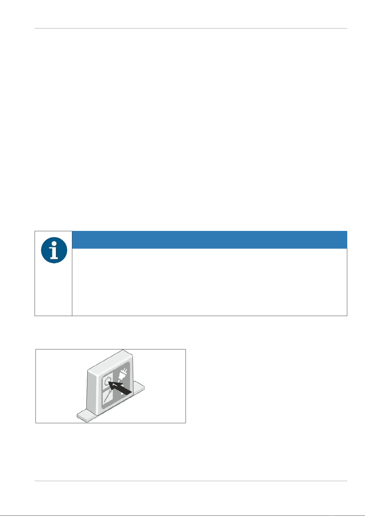
2.4 General power interruption
NOTE
A general power interruption has the following effects:
– Transactions in progress are canceled immediately (exception: ID card transport).
– Dispensed banknotes remain in the transport routes of the cash module. They are not
processed until the system is switched on again according to the configuration.
– Depending on the parameter setting, ID cards are either ejected, retained or transported
to the card reject tray. This transaction will be completed properly.
1. Access the external control unit (see Operator Manual, chapter "System overview", section "Chas-
sis components").
Figure2-1: Switching off the system
2. Switch the system off with the ON/OFF but-
ton of the external control unit (1).
Copyright © 2021, Diebold Nixdorf
01750340329 E
2-4

Safety
Figure2-2: General power interruption - Disconnecting the
plug
üThe type of plug used may differ depending
on the country of origin.
3. To ensure the power supply is fully discon-
nected, disconnect the power supply cable
from the electrical socket (1).
Alternatively, the power supply can be interrupted
by switching off the circuit-breaker or removing
the fuse from the distributor box of the facility in-
stallation.
Copyright © 2021, Diebold Nixdorf
01750340329 E
2-5

3
3 Description
3.1
3.1 System Overview
3.1.1
3.1.1 Overall View
3.1.1.1
3.1.1.1 Overall view from the front
TD-01575-01
Figure3-1: System overview – Overall view
1 System 2 Control Panel
Copyright © 2021, Diebold Nixdorf
01750340329 E
3-1

Description
3.1.1.2
3.1.1.2 Overall view from the rear
TD-01575-02
Figure3-2: System overview – Rear view
1 UPS (optional) 6 Rear door lock
2 System 7 Safe
3 Ventilation holes 8 Number combination lock
4 Operator panel inspection window (optional) 9 Locking/release handle of the safe
5 Lock of inspection window 10 Key-operated lock for the safe
Copyright © 2021, Diebold Nixdorf
01750340329 E
3-2

Description
Rear door opened (operator panel without inspection window)
1
6
5
2
7
3
4
9
8
TD-01575-03
Figure3-3: System overview – Rear door opened (operator panel without inspection window)
1PC 6Recycling module upper unit
2External control unit 7Release of the recycling module
3Operator panel 8Component carrier latch
4Release for fascia 9Component carrier grip
5Operator keyboard
Copyright © 2021, Diebold Nixdorf
01750340329 E
3-3

Description
Rear door opened (operator panel with inspection window)
1
7
6
2
8
3
4
5
9
10
TD-01575-04
Figure3-4: System overview – Rear door opened (operator panel without inspection window)
1PC 6Operator keyboard
2Release for the operator panel 7Recycling module upper unit
3Operator panel 8Release of the recycling module
4External control unit 9Release for the component carrier
5Release for fascia 10 Component carrier grip
Copyright © 2021, Diebold Nixdorf
01750340329 E
3-4
Other manuals for DN 250 Series
1
Table of contents
Other DIEBOLD NIXDORF Cash Counter manuals

DIEBOLD NIXDORF
DIEBOLD NIXDORF CINEO C4060 Installation instructions

DIEBOLD NIXDORF
DIEBOLD NIXDORF CS 7790 User manual

DIEBOLD NIXDORF
DIEBOLD NIXDORF CS 7780 User manual

DIEBOLD NIXDORF
DIEBOLD NIXDORF DN 490 User manual

DIEBOLD NIXDORF
DIEBOLD NIXDORF CS 5500 User manual

DIEBOLD NIXDORF
DIEBOLD NIXDORF CS 7750 User manual

DIEBOLD NIXDORF
DIEBOLD NIXDORF DN Series K32 User manual

DIEBOLD NIXDORF
DIEBOLD NIXDORF DN 400 Series User manual

DIEBOLD NIXDORF
DIEBOLD NIXDORF CS 5550 User manual

DIEBOLD NIXDORF
DIEBOLD NIXDORF CS 7700 User manual


