3.4 Power supply
When installed in a hazardous area the BA367E-SS
Counter should be powered via a certified Zener
barrier or galvanic isolator from a dc supply located
in the safe area or from associated apparatus with
an intrinsically safe output.
The input safety parameters of terminals 1 and 2
are:
Ui = 28V dc
Ii = 200mA dc
Pi = 0.84W
Any certified Zener barrier or galvanic isolator with
output safety parameters equal to or less than these
limits may be used.
The maximum equivalent capacitance and
inductance between terminals 1 and 2 is:
Ci = 2nF
Li = 4µH
To determine the maximum permissible cable
parameters the above figures, which are small and
may be ignored in many applications, should be
subtracted from the maximum permitted cable
parameters specified for the Zener barrier or
galvanic isolator powering the BA367E-SS Counter.
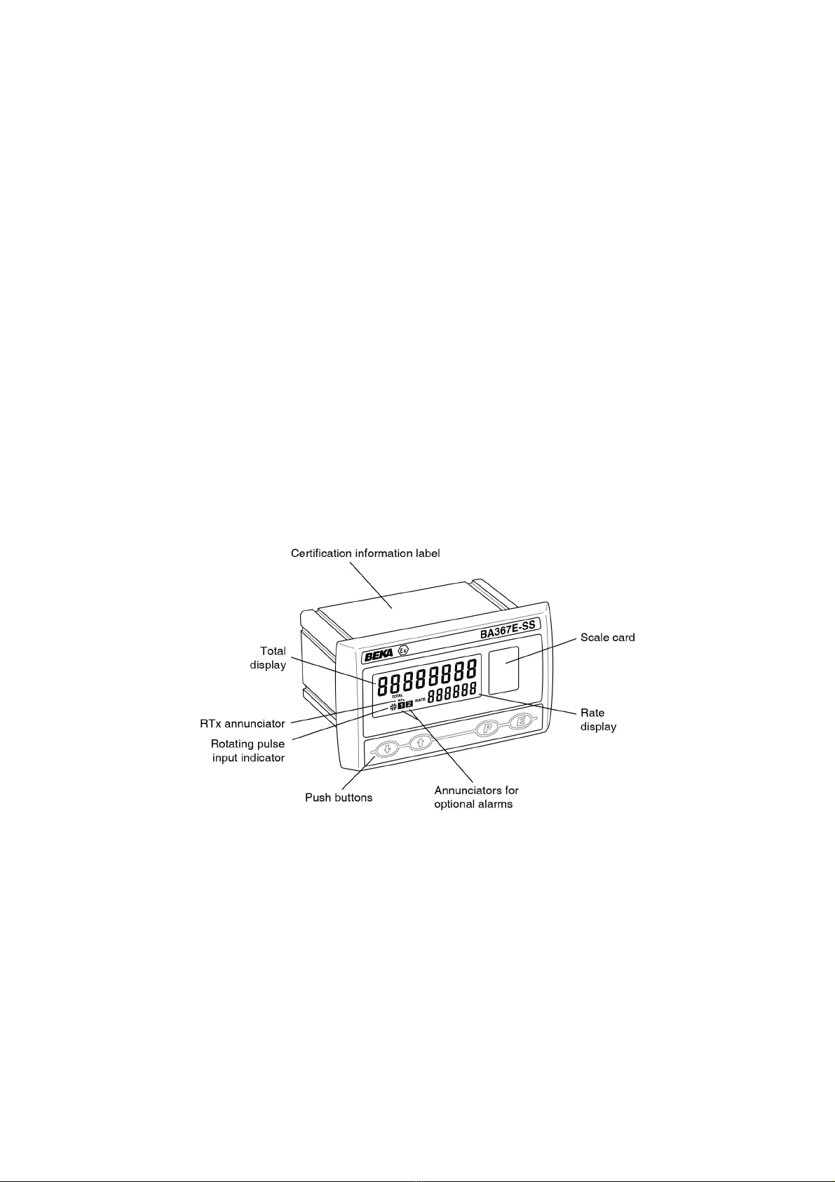
3.5 Pulse input terminals
The BA367E-SS pulse input is a separate
intrinsically safe circuit with the negative terminal
internally connected to the negative side of the
power supply terminal 2 and to the reset terminal
RS2. See Fig 1.
Some types of sensor that may be connected to the
BA367E-SS input, such as a switch contact or a
2-wire proximity detector, require energising to
determine their state. For sensors requiring
energising fitting an external link between terminals
3 & 4 of the BA367E-SS connects an internal 7V,
6mA supply to the input. Energising is not required
when the BA367E-SS input is connected to a
voltage source.
Fitting a link changes the output safety parameters
of the BA367E-SS Counter pulse input as shown in
the following table which also shows which types of
sensor require energising (link fitting).
Safety parameters
Type of input Link 3 & 4 Uo Io Po
Switch contact Yes 10.5V 8.2mA 25mW
Proximity detector Yes 10.5V 8.2mA 25mW
Open collector Yes 10.5V 8.2mA 25mW
Magnetic pick-off No 1V 11µA 3µW
Voltage input (low) No 1V 11µA 3µW
Voltage input (high) No 1V 11µA 3µW
3.5.1 Sensors that do not require energising
Magnetic pick-offs and voltage pulse inputs do not
require energising, see section 3.5. For intrinsic
safety purposes, sources of energy with output
parameters less than 1.5V; 100mA and 25mW are
considered to be simple apparatus (Clause 5.7 of
EN60079-11), which allows them to be ignored and
not documented when assessing an intrinsic safe
system.
When terminals 3 & 4 are not linked, the BA367E-SS
Counter input terminals comply with the
requirements for simple apparatus, thus allowing the
output parameters to be ignored when assessing the
safety of the sensor connected to the input.
This allows almost any certified intrinsically safe
voltage pulse circuit or certified magnetic pick-off to
be directly connected to the BA367E-SS Counter
input providing that:
a. The output parameters of the sensor or circuit
are equal to or less than:
Uo 28V dc
Io 200mA dc
Po 0.84W
b. The sensor and associated wiring can
withstand a 500V rms insulation test to earth.
The BA367E-SS EC-Type Examination
Certificate specifies that the equivalent
capacitance and inductance of the
BA367E-SS Counter input is:
Ci = 2nF
Li = 4H
To determine the maximum permissible cable
parameters these figures should be
subtracted from the maximum permitted
cable parameters specified for the sensor or
circuit connected to the input terminals of the
Counter. These input parameters are very
small and are therefore unlikely to make any
significant difference to the allowable cable
parameters.
c. The sensor is located in the same hazardous
area as the BA367E-SS.
8