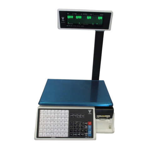
Digi SM-500MK4 User manual

COPYRIGHT © 2006 TERAOKA WEIGH-SYSTEM PTE LTD
SERVICE MANUAL
DIGITAL COMPUTING PRINTING SCALE
SM-500MK4
Edition 1
All manuals and user guides at all-guides.com
all-guides.com

1
Table of Content
i) Notice 1
ii) Safety Information ..............................................................................................................................2
1. GENERAL ....................................................................................................................................................3
1.1 Model Specification ............................................................................................................................3
1.2 Operating Specification......................................................................................................................4
1.3 Type of Interface ................................................................................................................................4
1.4 Main Components ..............................................................................................................................4
2. OVERVIEW ..................................................................................................................................................5
2.1 Dimension ..........................................................................................................................................5
2.1.1 Pole ......................................................................................................................................5
2.1.2 Touch Screen Pole...............................................................................................................5
2.1.3 Bench ...................................................................................................................................6
2.2 Key sheet Layout ...............................................................................................................................7
2.3 Panel Layout ....................................................................................................................................10
3. SPAN SWITCH ..........................................................................................................................................11
3.1 Span Switch Jumper Setting Changing Procedure ..........................................................................11
3.2 Span Switch located in Main Board..................................................................................................11
4. INITIAL SETUP ..........................................................................................................................................12
4.1 Scale Assembly ................................................................................................................................12
4.1.1 Display Pole Kit Mounting ...................................................................................................12
4.1.2 Level Adjustment ................................................................................................................12
4.2 Software Setting ...............................................................................................................................12
4.2.1 Memory Initialization ...........................................................................................................12
4.3 Calibration ........................................................................................................................................16
4.4 User Spec Setup Procedure.............................................................................................................17
4.5 Weigh & Measurement Spec Setup Procedure ..............................................................................19
5. HARDWARE TESTING & MAINTENANCE ..............................................................................................21
5.1 Hardware Testing.............................................................................................................................21
5.1.1 RAM Read and Write Test ..................................................................................................21
5.1.2 SIO Loop Back Test............................................................................................................22
5.1.3 RS485 Loop Back Test .......................................................................................................22
5.1.4 Ethernet Loop Back Test ....................................................................................................22
5.1.5 ROM Checksum Test..........................................................................................................23
5.1.6 PLU Generator Test............................................................................................................23
5.1.7 Internal Count......................................................................................................................24
5.1.8 Span Switch Status.............................................................................................................25
5.2 Adjustment........................................................................................................................................25
All manuals and user guides at all-guides.com

2
5.2.1 Location of Gap Sensor And Peel Sensor. .........................................................................25
5.2.2 Label Gap Sensor ...............................................................................................................25
5.2.3 Peel Sensor.........................................................................................................................26
5.2.4 Printing Position ..................................................................................................................27
5.3 Maintenance.....................................................................................................................................28
5.3.1 Thermal Head Cleaning ......................................................................................................28
5.3.2 Basic Maintenance.............................................................................................................29
5.3.3 Thermal Head cleaning and replacement ..........................................................................30
5.4 Method of Assembly Sealing Screw & Sticker .................................................................................31
6. DISASSEMBLY..........................................................................................................................................33
6.1 Pole Type Disassembly....................................................................................................................33
6.2 AD Board Disassembly ....................................................................................................................36
6.3 Loadcell Disassembly ......................................................................................................................37
6.4 Extra Bracket Disassembly for 30Kg................................................................................................38
7. FIRMWARE UPGRADE .............................................................................................................................39
7.1 Boot loader Downloading.................................................................................................................39
7.2 Firmware Downloading ....................................................................................................................42
8. HARDWARE SETTING..............................................................................................................................46
8.1 Main Board Jumper Setting..............................................................................................................46
9. MISCELLANEOUS ....................................................................................................................................46
9.1 Error Messages ................................................................................................................................46
9.2 Corresponding Key of IBM Keyboard...............................................................................................48
9.3 ASCII Characters..............................................................................................................................48
9.4 TERAOKA Code...............................................................................................................................49
9.5 Wire And Connector .........................................................................................................................49
9.5.1 Straight & Crossover Ethernet Cable.................................................................................49
9.5.2 Cash Drawer Option (RJ11)...............................................................................................50
9.5.3 PS2 Keyboard Option ........................................................................................................51
9.5.4 RS232C and Multi-Drop (4 Line, RS485) Wire ..................................................................51
10. APPENDIX .................................................................................................................................................55
10.1 Block Diagram..................................................................................................................................55
10.1.1 Bench Type.........................................................................................................................55
10.1.2 Touch Screen Pole Type ....................................................................................................56
10.1.3 Elevated Type .....................................................................................................................57
10.2 Specification List.............................................................................................................................58
10.2.1 User Specification [REZERO] + [1][4][1] ............................................................................58
10.2.2 Weigh & Measure Specification [REZERO] + [1][4][2].......................................................83
10.2.3 Weigh & Measure Specification [REZERO] + [1][4][1] (For SM90TS, SM500TS and
SM500MK4TS)...................................................................................................................91
11. REVISION RECORDS ...............................................................................................................................92
All manuals and user guides at all-guides.com

1
i) Notice
DIGI®
The material contained in this document is proprietary and for information only and is subject to change without
notice. Teraoka Weigh-System assumes no responsibility for any errors or damages arising from
misinterpretation of any procedure.
Screen displays, operating procedures and supporting features might vary with different software version
releases.
This document shall not be reproduced whether in part or whole without the written consent from Teraoka
Weigh-System Pte Ltd.
Teraoka Weigh-System Pte Ltd
4, Leng Kee Road
#06-01 SIS Building
Singapore 159088
All manuals and user guides at all-guides.com

2
ii) Safety Information
The operator of the equipment shall comply with the safety and warning indications and procedures outlined in
this document. Teraoka Weigh-System Pte Ltd assumes no responsibility or liability for failure to comply with
these requirements.
• To avoid electric shock, use only the supplied power cords and ensure product is connected to a
properly grounded supply.
• For continued protection against fire hazard replace only with fuse of same rating and type.
• Ensure product is placed on a firm and level surface before operation.
• Avoid overloading the product beyond its rated maximum capacity
• Ensure commodity to be weighed is loaded centrally on the platter.
- Avoid placing commodity on corners or edges.
• Care shall be taken during the following operations
o Receipt paper tearing – to prevent injuries from cutting from paper cutter
o Changing of labels and receipt paper - to prevent injuries from cutting from paper cutter and
movable printer mechanism.
• Trained and qualified personnel shall only carry out repair and servicing of product.
Disclaimer:
Specifications are subject to change without notice. All dimensions shown are approximate. Please be aware
that Teraoka has indicated that its hardware and software used in the product may require additional updates in
the future as our product is continually under development. The need for such updates most likely applies to the
Printer software.
CAUTIONS:
1. FOR PLUGGABLE EQUIPMENT, THAT THE SOCKET-OUTLET SHALL BE INSTALLED NEAR THE
EQUIPMENT AND SHALL BE EASILY ACCESSIBLE.
2. FOR CONTINUED PROTECTION AGAINST RISK OF FIRE, REPLACE ONLY WITH SAME TYPE
AND RATING OF FUSE.
3. DANGER OF EXPLOSION IF BATTERY IS INCORRECTLY REPLACED. REPLACE ONLY WITH
THE SAME OR EQUIVALENT TYPE THAT RECOMMENDED. DISPOSE OF USED BATTERY
ACCORDINGS TO THE MANUFACTURER’S INSTRUCTIONS.
All manuals and user guides at all-guides.com

SM500MK4 Service Manual
3
1. GENERAL
1.1 Model Specification
Model : SM-500MK4
Variation : Dual Pole -SM-500MK4 DP
: Economic Bench -SM-500MK4 EB
: Elevated -SM-500MK4 EV
Capacity : 6/ 15/ 30 Kg
Key : Mechanical Switch
Number Of Preset Key : 32/ 56/ 100 Preset keys
: 48/ 60/ 96/ 108/ 120 Preset keys (For Self-Service machine used)
Display Resolution : 1/3000 (Multiple Interval)
1/6000 or 1/7500 (Single Range)
Internal Resolution : 1 / 60000
Printer Type : Cassette Type
A) Paper : Label & Receipt
:
Label (Standard) - 40mm to 72mm
B) Paper Width
: Label (Option) - 40mm to 80 mm
: Receipt - 72mm / 80mm
C) Resolution : 8 dots / mm
:
Label - 150mm / sec
D) Speed
: Receipt - 150mm / sec
Note: For Best Speed and Printing Resolution, use Ricoh paper,
150LAB
Memory : 2 M Byte (Standard)
All manuals and user guides at all-guides.com
all-guides.com

SM500MK4 Service Manual
4
1.2 Operating Specification
Power Source : 100V to 240V AC (Auto Switching)
Frequency : 50 - 60 Hz
Operating Temperature : -10 °C to 40 °C
Humidity : 15 % to 85 % RH
Waterproof : N.A.
(Please do not splash water on top or around the scale. Clean scale
only with a damp cloth)
1.3 Type of Interface
Standard : RS 232C (FL-1, PC connection)
:
PS2 Keyboard
:
Cash drawer (3 Pin for TWB-01750)
: Cash drawer (RJ11 type for TWB-01750-1 onward)
RS 485 (PC connection)Optional
:
Ethernet (Client / Server, TCP / IP protocol)
: Character Generator
* Interface with PC can either use RS 232C, RS 485 or Ethernet.
1.4 Main Components
1 XYLINX-XC95144XL-
10TQG144C.
(M/B-U1)
It’s a 3.3V CPLD targeted for high-performance, low-voltage application in leading-
edge communications and computing system.
2 Motor Driver L6258EX.
(M/B-U5)
It’s a dual full bridge for motor control application realized in BCD technology, with
the capability of driver both winding of a bipolar stepper motor or bi-directional
control two DC motor.
3 RS232 Drv AX3232.
(M/B-U18)
It’s a device consists of two line driver, two receiver, and a dual change-pump circuit
with +-15kv ESD protection pin to pin.
4 Controller H8/3024F.
(CPU BD-U1)
It’s a high-performance single-chip microcomputer that integrates peripheral
functions necessary y for system configuration with an H8/300H CPU feature a 32-
bits internal architecture as its core.
5 SRAM
IS62WV51216BLL.
(CPU BD-U7 & U8)
It’s a high-performance, very low power CMOS static Random Access Memory
organized as 524,288 words by 16 bits and operates from a wide range of 2.4V to
5.5V supply voltage.
6 AM29LV320DB90EI.
(CPU BD-U9)
It’s a 32 megabit, 3.0 volt-only flash memory device, and is designed to be
programmed in-system with the standard 3.0 volt Vcc supply, and can also be
programmed in standard EPROM programmers.
7 LAN9115-MT.
(CPU BD-U10)
Is a full-featured, single chip 10/100 Ethernet controller designed for Embedded
applications where performance, flexibility, ease of integration and system cost
control are required
*Components are subject to change without notice.
All manuals and user guides at all-guides.com

SM500MK4 Service Manual
5
2. OVERVIEW
2.1 Dimension
Dimensions are in mm
2.1.1 Pole
570
480
335
408
2.1.2 Touch Screen Pole
335
408
570
480
All manuals and user guides at all-guides.com

SM500MK4 Service Manual
6
2.1.3 Bench
462
154
All manuals and user guides at all-guides.com

SM500MK4 Service Manual
7
2.2 Key sheet Layout
32 Preset Keys
56 Preset Keys
100 Preset Keys
All manuals and user guides at all-guides.com

SM500MK4 Service Manual
8
ON / OFF KEY
* Turn display ON or OFF.
NUMERIC KEYS
To
* Enter numeric data.
TARE KEY
* Set or Clear Tare Value.
* Select " NO " in S and Z Mode.
* Item Test print in S Mode.
CLEAR KEY
* Clear numeric values.
* Select " YES " in S and Z Mode.
RE-ZERO KEY
* Reset weight to zero.
PRE-PACK KEY
* Switch Manual mode and Pre-pack mode alternatively.
(The mode status will be indicated in the P and M indicator.)
▪P - PRE-PACK MODE ▪M - MANUAL MODE
CHANGE KEY
* Calculate the Changed Amount.
* Escape the Programming screen without saving data in S mode.
MULTIPLE KEY
* Register the number of Non-Weight products.
* Select programming item such as PLU data, Shop Name in S
mode.
* Select Report Type in X mode.
* Select Data Transaction Type in Z mode.
CLERK KEYS
* Accumulate the Total Price.
All manuals and user guides at all-guides.com
all-guides.com

SM500MK4 Service Manual
9
VOID KEY
* Correct the Sales Data
PLU KEY
* Call up PLU data.
* Store the programmed data in S mode.
FEED KEY
* Feed Label or Receipt
PRINT KEY
* Print out Label or Receipt
MODE SELECT KEY
* Five Modes can be selected using this key.
Indicator R - REGISTRATION MODE (All the sales transactions are
performed.)
Indicator X - CHECK MODE (Printing out and sales report.)
Indicator S - PROGRAM MODE (Programming preset data, such as
products, data, shop name, etc.)
Indicator Z - TOTAL MODE (Clear sales data stored.)
Indicator X (Blink) - PASWORD SETTING MODE (Setting ENTRY
PASSWORD for S, X and Z modes.)
PRESET KEYS
to
* Call up Preset data such as PLU Data or Function Data in Reg.
Mode.
* Enter Alphabetic data in Program Mode.
Note: The following Preset Keys are used in entering Alphabetic (Pole Type).
Move the
cursor.
Change the
entry to
Right.
Move the
cursor.
Change the
entry to Left.
Code type
entered.
Insert Data. Switch Cap /
Lower case.
Change Font
size.
Delete the
Data.
All manuals and user guides at all-guides.com

SM500MK4 Service Manual
10
2.3 Panel Layout
Bench and Pole Type (For 300 LCD)
There are fifteen different indicators on Display Panel as shown below.
1. Î0Í: Lights when scale is stable at the zero point
2. NET : Lights when tare subtraction in performed.
3. P: Lights when PRE-PACK Mode is selected.
4. MAN : Lights when MANUAL Mode is selected.
5. AM : Lights when the amount is displayed.
6. CH : Lights when the amount of change is being displayed.
7. PE : Lights when label or receipt paper ends.
8. R: Lights when REGISTRATION Mode is selected.
9. X: Lights when CHECK Mode is selected.
10. S: Light when PROGRAM Mode is selected.
11. Z: Lights when TOTAL Mode is selected.
12. A: Lights when Sales Data is in Memory for CLERK 9995.
13. B: Lights when Sales Data is in Memory for CLERK 9996.
14. C: Lights when Sales Data is in Memory for CLERK 9997.
15. D: Lights when Sales Data is in Memory for CLERK 9998.
All manuals and user guides at all-guides.com

SM500MK4 Service Manual
11
3. SPAN SWITCH
3.1 Span Switch Jumper Setting Changing Procedure
1. Bottom View of Machine.
2. Loosen the 4pcs SEMS B
screw M4X6, then open the
Bottom Cover.
3. Loosen the 2pcs Truss Head
screw M4X6, and disconnect
the Interface Board cable.
4. Loosen the 2pcs SEMS B
screw M3X6, then open the
Insulator.
5. Change [SW2] jumper to
Enable/Disable Span Switch.
3.2 Span Switch located in Main Board
Interface
Board
Cable
Span Switch
(
SW2
)
Mainboard
Insulator
Insulator
All manuals and user guides at all-guides.com

SM500MK4 Service Manual
12
4. INITIAL SETUP
4.1 Scale Assembly
4.1.1 Display Pole Kit Mounting
4.1.2 Level Adjustment
4.2 Software Setting
4.2.1 Memory Initialization
There are two methods of memory initialization.
4.2.1.1 Default Country Specification 1
Default Customer Specification and Weight & Measure Specification setting of individual country.
(Please turn on the span switch before proceed this process.)
KEY TO PRESS OPERATION
+Switch On the Power.
-- Show current country SPEC then default
Customer Specification setting.
-- Follow the instruction:
a) Press the [Clear] then
b) Press the [Print] process to next step
1. Place the display Pole inside the pole
bottom (base AB)
2. Align the four holes of the display pole
and ti
g
hten screw Flat Head M4x16
Place the scale on the flat surface and
adjust the four legs until the bubble on the
level is in the center as shown above.
All manuals and user guides at all-guides.com

SM500MK4 Service Manual
13
KEY TO PRESS OPERATION
[0] To [8] -- Select scale type.
OR
&-- Select scale type.
Then
-- To set the scale type.
KEY TO PRESS OPERATION
[0] To [1] -- Select label length.
OR
&-- Select label length.
Then
-- To set the label length.
Key to press Operation
-- Reading Country Specification.
Key to press Operation
-- After Reading Country Spec, the display will
prompt MEMORY CLEAR message.
Scale Type:
0: Pole 6 Kg
1: Pole 15 Kg
2: Pole 30 Kg
3: Pole 30 Lb
4. Bench 6 Kg
5: Bench 15 Kg
6: Bench 30 Kg
7: Bench 30 Lb
8: Printer
(
BP 80/90
)
Label Length:
0: Short
ÆLabel length up to
maximum 120mm.
1: Long
ÆLabel length up to
maximum 240mm
All manuals and user guides at all-guides.com
all-guides.com

SM500MK4 Service Manual
14
Key to press Operation
If Yes,
-- Process of initialize.
-- Then go to segment check.
PLEASE WAIT
Key to press Operation
If No,
-- Go to segment check.
4.2.1.2 Default Country Specification 1
Key to press Operation
[9] +[3] Switch On the Power.
-- Show current country SPEC then default
Customer Specification setting.
-- Follow the instruction:
a) Press the [Clear] then
b) Press the [Print] process to next step
KEY TO PRESS OPERATION
[0] To [1] -- Select label length.
OR
&-- Select label length.
Then
-- To set the label length.
Label Length:
0: Short
ÆLabel length up to
maximum 120mm.
1: Long
ÆLabel length up to
maximum 240mm
All manuals and user guides at all-guides.com

SM500MK4 Service Manual
15
Key to press Operation
-- Reading Country Specification.
Key to press Operation
-- After Reading Country Spec, the display will
prompt MEMORY CLEAR message.
Key to press Operation
If Yes, press
-- Process of initialize.
-- Then go to segment check.
OR
If No, press
-- Go to segment check.
All manuals and user guides at all-guides.com

SM500MK4 Service Manual
16
4.3 Calibration
Key to press Operation
In the Weighing Mode, press
then turn On the Span Switch.
-- Go to Z mode
KEY TO PRESS OPERATION
+[8][7][1][5]
-- Access code to calibration mode.
KEY TO PRESS OPERATION
-- To calibrate zero point.
-- Ensure no weight in platter
-- Wait until the ‘ SET WEIGHT & PRT ’ shows
KEY TO PRESS OPERATION
Place the capacity weight on the scale after the
following screen appears.
-- Place the capacity weight according to the scale
on the platter. E.g. for a 6 Kg scale, put a 6 Kg
capacity weight on the platter.
KEY TO PRESS OPERATION
Press Mode key exit -- Calibration finish
All manuals and user guides at all-guides.com

SM500MK4 Service Manual
17
4.4 User Spec Setup Procedure
To Change the setting of the User SPEC, if there is some SPEC need to alter.
KEY TO PRESS OPERATION
In the Weighing Mode, press
then turn On the Span Switch.
-- Go to Z mode.
KEY TO PRESS OPERATION
+ [1][4][1] -- Go to User Specification Mode
-- To change the selection for the Spec, press the
Number of the selection
-- Press the key to Save go to next Spec
-- Press ‘-‘ key to go back to previous Spec
-- Press ‘PLU’ to save and exit
-- Press ‘Tare’ to exit without saving
KEY TO PRESS OPERATION
[0] To [2][0] -- Select data. (Refers to Customer Spec setting)
OR
& -- To choose scale type.
Then
-- To set. (Save data and increase SPEC No)
KEY TO PRESS OPERATION
-- Increase the SPEC number without saving data of
the previous SPEC number.
All manuals and user guides at all-guides.com
This manual suits for next models
2
Table of contents
Other Digi Scale manuals

Digi
Digi DS-685L Series User manual

Digi
Digi DI-600 User manual

Digi
Digi DC-190 Series User manual

Digi
Digi DC-190 ULTRA COUNT User manual

Digi
Digi SM-100 User manual

Digi
Digi DC-190 ULTRA COUNT User manual

Digi
Digi DS-425 User manual

Digi
Digi DS-470 User manual

Digi
Digi SM-720 User manual

Digi
Digi SM-5300 Series User manual