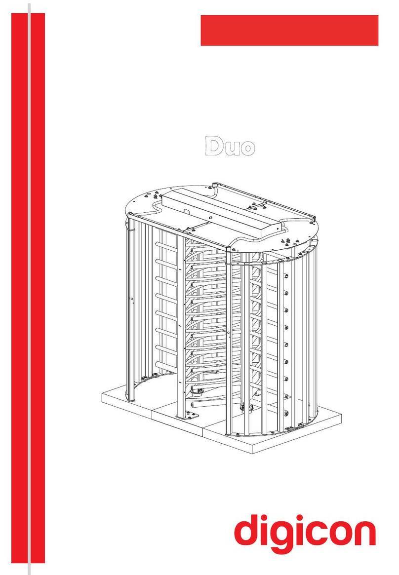
digicon dflow User manual

1
Product Manual
11
1

2
2

3
Revision Date Reviser History
07 29/APR/2020 ŸBruno Hayashi
Beal
ŸMário Arand
ŸNew manual layout;
ŸContent update.

4
3
After the product's service life ends, dispose ofi t according to the National
Solid Waste Policy.
Copyright– Digicon S.A.
Controle Eletrônico para Mecânica – 2020
Code: 069.31.220
Revision 07
This manual was elaborated by: Digicon S.A. Controle Eletrônico para Mecânica
Documentation Sector - EDS
All rights reserved. No part of this publication may be reproduced,
transmitted, transcribed, stored in a retrieval system, translated into any
language or computer language in any electronic, magnetic, optical,
chemical, manual way, or otherwise, without express written permission
from Digicon S.A.

5
4
Índice
06
06
06
07
09
09
11
14
14
14
15
16
19
22
24
25
25
27
27
31
31
32
32
33
33
33
34
34
35
37
38
40
40
40
40
40
41
1. ........................................................................................................Guidelines
2. .........................................................................................Environmental issues
3. ............................................................................................Additional manuals
4. ...........................................................................................Safety instructions
5. .....................................................................................................Introduction
6. ..............................................................................Characteristics and operation
7. .............................................................................................................Models
8. .......................................................................................................Installation
8.1 ......................................................................................Installation site
8.2 .....................................................................................Package content
8.3 ....................................................................................Accessing dFlow
8.4 ............................................................................Drilling and anchorage
8.5 .............................................................Fixating and powering the sensor
8.6 .............................................................Routing of interconnection cables
8.7 .....................................................Power connection and external network
9. .....................................................................................Powering the equipment
9.1 ...................................................................................Important checks
9.2 ..................................................................Turning on the circuit breaker
10. ........................................................................Configuration via selector switch
11. ...............................................................................................Optional items
11.1 .......................................................................................Card collector
11.2 Display ................................................................................................
11.3 No break .............................................................................................
11.4 ....................................................................................Bar code reader
11.5 ..................................................................Access control module - MCA
11.5.1 .................................................................................Antennas
11.5.2 ................................................................................Biometrics
11.5.3 ........................................................................Bar code reader
12. ...................................................................................Technical characteristics
12.1 ..........................................................................................Dimensions
12.2 .................................................................................Other information
13. ...................................................................................Preventive maintenance
14. .........................................................................................................Cleaning
14.1 ....................................................Maintenance and conservation of doors
1 .2 Maintenance and conservation passage control sensor4 ...............................
1 .34 Maintenance and conservation of dFlow (glasses and stainless steel sheets)..
15. .....................................................................Warranty and technical assistance
6
1.Guidelines
ŸRead the information carefully before using the product. This ensures the correct use
of the equipment and maximum use ofi ts technical features as well as prolonged
service life.
ŸThis product does not present sealing against rain, that is, it is designed to be used
indoors.
ŸThis product was not designed to be placed directly under sunlight.
ŸKeep this manual for future consultations.
ŸDigicon reserves its right to alter the characteristics ofi ts products at any moment to
adapt them to more recent technological advancements.
ŸDigicon maintains its right to alter the information contained in this manual without
previous notice.
ŸDigicon does not provide any contractual warranty concerning the information in this
manual and cannot be held responsible for errors it may contain and problems due to
its use.
ŸThe information contained in this manual is exclusive property of Digicon and is
protected by copyright laws.
ŸThis manual cannot be reproduced, photocopied or translated, in its entirety or in
part, into any kind of medium, without Digicon's written consent.
ŸThe equipment described here is customizable, that is, this manual describes all
possible models and they may not reflect, necessarily, the model purchased by the
customer.
2.Environmental issues
The materials used in the product packaging are easily separated (screws, bubble
wrap, wood, cardboard), which makes disposing of the items more accessible.
The dFlow equipment has recyclable and/or reusable materials in its building. In case
of exchange of parts or components, dispose of the parts with specialized services.
In case of disposal of equipment, make sure to follow the local valid regulations.
3. Additional manuals
Besides this manual, we offer other three documents:
ŸIntegrator manual
ŸSupport and maintenance manual
ŸWork plan manual

7
4. Safety Instructions
This manual has several safety messages: try to read and follow them in order to
promote your safety and that of third parties.
ŸApplicable symbols:
ŸTerminology:
The terms defined below are used in this document. The definitions are based on those
found in safety regulations in order to direct tasks for a certain target audience.
Technical professiona:lthe term applies to trained or qualified people who have
permission to install or replace technical equipment or to offer technical support. It is
recommended that the technical professional use his experience and technical abilities
to avoid possible injuries regarding himself and others due to the risks in areas of
restricted access.
User and operato:rthe terms user and operator apply to people who are not
technical professionals.
ŸInformative
It indicates important instructions concerning operation or maintenance.
It indicates a powered terminal where dangerous voltage may be present.
It indicates a protective ground wire.
WARNING
- Electrical shock can cause serious personal injuries and even death;
thus, avoid direct contact with dangerous voltages while handling the
equipment.
- Ground wiring is essential for safe operation: make sure the power
network meets this requirement safely.
- Only qualified technical professionals are allowed to install and
perform maintenance in the equipment.
- Before any maintenance, switch the circuit breaker off to stop
into the equipment.
the power

8
ŸGeneral precautions:
Wristwatch and jewelry– To avoid damages to the equipment and to the operator,
do not wear objects that conduct electricity.
Atmospheric discharges –Do not work on this equipment during atmospheric
discharges.
Labels– Do not remove warning labels. If the item is illegible or damaged, replace it
by a new label.
Children– Do not leave unattended children near the equipment.
ESD– Electrostatic discharge.
I. Keep the components inside the antistatic package until installation.
II. Avoid touching the electronic components when installing a module or board.
WARNING
Avoid electricalshock! Opening or removing the doors of this equipment
can expose it to dangerous voltages.
WARNING
To reduce the risk of electric shock, before maintenance, turn off the power
of the equipment by moving the circuit breaker key to the position OFF.
Leave all maintenance services to qualified technical professionals.

9
5. Introduction
6. Characteristics and operation
NOTE-dFlow is a configurable equipment and can be provided with the option
of closed doors.
When we combine innovation and robustness, design and reliability, we find the best
access control solution. Digicon presents a solution developed to the last detail in order
to offer a new concept to the market. From an intense research process on world
tendencies and a comprehensive engineering work, dFlow is born.
dFlow is the first access controller that perfectly fits into the Free Flow concept. This is a
new way of conceiving access control because its doors remain normally open, while
traditional equipment have barriers in the normally closed position. This paradigm shift
is what differentiates it from a Free Flow currently available.
Even though it seems that equipment is always open, it has doors. They are activated
only when one or more unauthorized people, including tailgating users, try to go through
the equipment. The closing system is fast and progressive, performed by a set of the
exclusive motor control, innovative sensing, and sophisticated algorithm. This results in
a very pleasant and fast experience for authorized users and offers unprecedented
levels of security for the establishment.

10
The technology developed in Brazil by Digicon detects, with high precision, users
moving in any direction inside the equipment. Such precision originates in the
innovative sensing system, which can be compared to an almost limitless amount of
traditional infrared sensors, thus allowing the doors to remain open for authorized
users and closed to non-authorized people.
Luminous windows made of LED lights follow users during their path inside the equipment.
They can have different colors for each user group. In a school, for example, students can
belong to the green-colored group, educators to the yellow-colored group, and parents to the
blue-colored group. Users without validation will be displayed in red. dFlow's flexibility allows
other user groups to be identified by an extensive range of colors, thus providing more
information to the access system.

11
dFlow accepts the main traditional identification technologies, including bar code, QR
code, RFID, MIFARE, and biometrics via fingerprint. Integration into such technologies
follow the standards used in the traditional access control equipment.
New biometric technologies now emerging, as facial identification, iris pattern
identification, and finger on the fly are also supported by dFlow. These concepts offer a
faster and contactless experience with the equipment, making the Free Flow concept
even more pronounced.
7. Models
There are three types of models for dFlow. All of them use the same sensing system;
however, each model has a different passage width.
I. Model 500
In this model 500, the passage width measures 520 millimeters. With such measure,
we are able to have a bidirectional, non-simultaneous flow.

12
II. Model 900
NOTE-The model 900 can be configured with centralized doors.
NOTE-Digicon meets the standard ABNT NBR 9050, Accessibility to buildings,
furniture, and urban equipment.
In this model, the passage width measures 920 millimeters. With such measure, we
are able to have a bidirectional, simultaneous flow as well as providing access to
Special Needs Users.

13
III. Model 1100
NOTE – Each dFlow passage has 2 bumpers (left and right) whose function is to
protect the equipment against mechanical shocks. The bumpers, with 10 mm each,
reduce the useful passage width from 1140/940/540 mm to 1120/920/520 mm in the
active area.
Receiver /
Transmitter
Receiver /
Transmitter
940mm
(37.007")
1140mm
(44,881")
1120mm
(44,094")
920mm
(36.220")
Transmitter Transmitter
540mm
(21.259")
520mm
(20.472")
Bumper
Entry Entry Entry
In this model, the passage width measures 1120 millimeters. Exclusively in this model
the doors are centralized, which does affect the bidirectional, simultaneous flow and
allows access to Special Needs Users.

14
8. Installation
8.1 Installation site
The installation site must follow the requirements listed in the document titled Work
Plan in order to receive the equipment installation. In that document there are all the
information needed to install the product correctly, so that it can meet the customer's
expectations.
Alongside the document, there is a checklist of the installation requirements, which
must be filled in, signed by the customers, and documented by the company
responsible for installation.
NOTE –Evidences of the fulfillment of the installation requirements must be sent to
the technician's analysis. That can be done via photos or videos, as long as they have
clear information.
8.2 Package content
Before beginning installation, it is very important to perform a checklist of the
received items. This helps prevent future stops during installation due to lack of
materials. If you perceive any item missing, contact the company responsible for the
sale.
WARNING
Use two or more people to move/install the equipment. Excess can damage
or hurt someone who tries to perform this task alone.
WARNING
Allow only qualified personnel to install this equipment. The
installation must comply with all local rules and regulations.

15
Motors
and communication
terminals
Access cover to
Electrical panel and engine
Access cover
to breakercircuit
8.3 Accessing dFlow
Each equipment module has four covers accessible via keys:
ŸSide covers: offer access to the breaker, collecting box, motor boardcircuit
supplies, and selector switch.
ŸLower covers: offer access to motors, control board, CPU, terminals, and
integrator area.
Opening doors: Closing doors:
WARNING
Make sure the circuit breaker is in the OFF position. This prevents the
accidental equipment energization during installation.

16
8.4 Drilling and anchorage
NOTE -Make sure the installation surface is steady and leveled to ensure door
alignment and a better sensor performance.
Place the equipment or templates in the correct installation place and check ifi t corresponds
to the model purchased by the customer. Below you can see the measurements according to
the models:
1600
250 250
320 320
230 230
(62.99")
(12.59") (9.84") (9.84")(9.05")
Cables passage
280 280
220 220
220
190 190
60
90
160
(11.02") (11.02")
(8.66") (8.66")
(8.66")
(3.54")
(6.29")
(22.36")
(7.48") (7.48")
(9.05")
(12.59")
- Fixation points - Optional fixation points
(21.259")
540
610
700
(24.015")
Model 500
(27.559")
To anchor the equipment to the floor, we must prepare the drill holes according to the
measures shown below:

17
(37.007") (44.881")
940 1140
1010 1210
1100 1300
(39.763") (47.637")
(43.307")
Model 900
(51.181")
Model 1100
Once the layout is placed and the measurements are checked, mark the floor drilling
points, remove the template and drill according to the chosen type of anchor
(mechanical or chemical).
NOTE: Digicon recommends the chemical anchorage with ampoules. Check the
manufacturer's information before perfoming the chose anchorage.

18
Make sure the modules follow the positions shown below:
NOTE – In order to differentiate the modules, we point out that the
receiver has the CPU and the control board while the transmitter only has the terminal
block B2 in the lower half of the product.
Entry
Entry Entry
Transmitter
Transmitter Transmitter/
Receiver
Receiver
Receiver

19
8.5 Fixating and powering the sensor
Tofixate the sensor correctly, check if the installation references are according to the
ones specified below:
Inside the set, there is a kit containing screws and the connector used to power the
sensor. Use these items to fixate the sensor to the structure organized by the
customer.
NOTE – If the anchor system provided does not fit the local requirements, it is
possible to replace it as long as the new system does not mechanically interfere with
the sensor.
3080 (121,25")

20
During installation, it is important to respect the correct position of the sensor. The
engraving 'TR' on the fixation sheet guides the positioning of the transmitter and
receiver modules while the arrow indicates the equipment's direction of entry.
Entry
Receiver
Transmitter
278 (10,94")
306 (12,04")
R52,5
R41,75
50
ØR3
R3
20
Other manuals for dflow
1
Table of contents
Other digicon Turnstile manuals
Popular Turnstile manuals by other brands

Tiso
Tiso ASTM F2656 M40 Installation and operation manual

ZKTeco
ZKTeco TS5000A Series user manual

Oxgard
Oxgard PRAKTIKA QL-04-SM-660 Installation guidelines

Magnetic Autocontrol
Magnetic Autocontrol MPT 33 operating instructions

Dormakaba
Dormakaba ALVARADO Supervisor 2000 user guide

Magnetic Autocontrol
Magnetic Autocontrol MPS-122 operating instructions