manuals.online logo
Brands
  1. Home
  2. •
  3. Brands
  4. •
  5. Dimplex
  6. •
  7. Temperature Controllers
  8. •
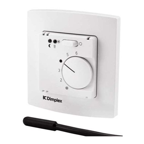
  9. Dimplex RTK 601 U User manual

Dimplex RTK 601 U User manual

RTK 601 U
01/08/A 1 5 21410 00 JD
Elektronischer Zweipunkt-Raumtemperaturregler Heizen/Kühlen zur UP-Montage im Flächenschalterrahmen extern umschaltbar
Externally commutable, electronic two-point room temperature controller (heating/cooling) for under plaster installation in a flush
framed switch
Thermostat électronique pour la régulation de la température ambiante à deux positions (chauffage/refroidissement), type à cadre
de recouvrement plat pour l’installation encastrée
Elektroniczny dwupunktowy regulator temperatury pomieszczenia pracujący w trybie ogrzewania / chłodzenia do montażu podtynkowego
w ramce, przełączany od zewnątrz
Sicherheitshinweis!
Dieses Gerät darf nur durch eine Elektrofachkraft geöffnet und gemäß dem entsprechenden
Schaltbild im Gehäusedeckel / auf dem Gehäuse / in der Bedienungsanleitung installiert
werden. Dabei sind die bestehenden Sicherheitsvorschriften zu beachten. Achtung! Der
Betrieb in der Nähe von Geräten, welche nicht den EMV-Richtlinien entsprechen, kann zur
Beeinflussung der Gerätefunktionen führen. Nach der Installation ist der Betreiber, durch die
ausführende Installationsfirma, in die Funktion und Bedienung der Regelung einzuweisen.
Die Bedienungsanleitung muss für Bedien- und Wartungspersonal an frei zugänglicher
Stelle aufbewahrt werden.
1. Anwendung
Dieser Regler wurde speziell zur Heiz-/Kühlregelung in 2-Rohrsystemen für Hotel-, Wohn-
und Geschäftsräume entwickelt. Er ist mittels Zwischenrahmen gemäß DIN 49075 in nahe-
zu alle Flächenschaltersysteme adaptierbar und kann bis zu 5 Ventilantriebe (24V~, strom-
los geschlossen) ansteuern.
2. Funktionen
3. Installation/Montage (s. Bild 2)
Der elektrische Anschluss ist gemäß dem Anschluss-Schaltbild (s. Punkt 7) vorzunehmen.
Achtung: Die Masse der Versorgungsspannung darf nicht mit der Masse der Fühler ver-
bunden werden, ein Zusammenschluss oder eine Verwechslung führt zur Zerstörung des
Reglers.
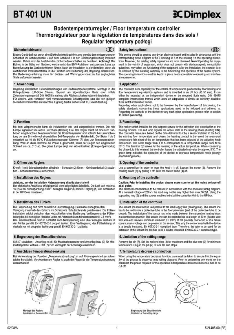
Zum Öffnen des Reglers (6) die Schraube (2) unter dem Einstellknopf (1) lösen und den
Gehäusedeckel (3) sowie den Rahmen (4) abziehen. Der Regler ist mittels Tragring (5) und
Schrauben in eine UP-Dose Ø 55mm auf die Tapete zu montieren.
Das Schließen des Reglers erfolgt in umgekehrter Reihenfolge. Es ist darauf zu achten,
dass der Regler auch rückseitig in der UP-Dose keiner Fremderwärmung oder -kühlung z.B.
durch Zugluft bei Hohlwänden oder Steigleitungen ausgesetzt wird.
3. Installation (see Figure 2)
The device must be connected electrically in accordance with the circuit diagram (see Item 7).
Note! The ground conductor of the voltage supply cable must not be connected to the sensor
ground, as any such wrong connection or mismating will result in the destruction of the con-
troller.
To open the controller (6), loosen the screw (2) underneath the adjusting knob (1) and pull off
the housing cover (3) including the frame (4). The controller is to be installed by means of a
supporting ring (5) and screws into a concealed mains socket of 55mm diameter on the wall
paper.
The controller is closed in the reverse sequence. Care must be taken to ensure that the con-
troller is not exposed to any outside heating or cooling, for example, by draughts in hollow
walls or risers.
Safety Instructions!
This device should be opened only by an electrical expert and installed in accordance with the
corresponding circuit diagram in the E housing lid / on the housing / in the operating instruc-
tions. Moreover, the existing safety regulations are to be observed. Note! Operating the equip-
ment in the vicinity of equipment, which does not comply with electromagnetic compatibility
guidelines, may affect the functioning of the equipment. After the installation, the operator is to
be oriented by the installing company in the functioning and operation of the control system.
The operating instructions must be kept in a place freely accessible to operating and mainten-
ance personnel.
1. Application
This device has been designed especially for controlling the heating/cooling operations in
two-tube systems in hotels, living rooms and business offices. It can be mounted flush using
DIN 49075 compliant intermediate frames, which permit it to be adapted to almost all flush
switch systems. It can control up to 5 valve drives (24V~, closed current-free).
DGB
2.1. Heiz-/Kühlumschaltung im 2-Rohrsystem (Change-Over-Funktion)
Der Raumtemperaturregler Heizen/Kühlen misst mit einem internen Fühler die Raumtempe-
ratur. Er aktiviert bei Abweichung zum eingestellten Sollwert in Abhängigkeit von der Be-
triebsart (Heizbetrieb bzw. Kühlbetrieb) den gemeinsamen Schaltausgang Heizen/Kühlen.
Die Betriebsart wird mit einem externen Kontakt (Change-Over-Kontakt H/C) gewählt. So ist
es möglich eine zentrale Umschaltung für alle Regler zu realisieren. Achtung! Auf Grund
der internen Gerätebelastung dürfen nur maximal 20 Geräte über einen Schaltkontakt um-
geschaltet werden. Bei mehr als 20 Geräte sind entsprechend mehr Kontakte zu verwen-
den.
Kontaktfunktion: Kontakt geöffnet = Heizbetrieb, Kontakt geschlossen = Kühlbetrieb
2.2 Kühlunterbrechung bei Kondensatbildung durch optionalen Taupunktsensor
Die Funktion Kühlen kann bei Kondensatbildung durch einen optionalen externen Sensor
unterbrochen werden. Der Taupunktsensor muss an den Ort mit der größten Taupunktwahr-
scheinlichkeit an den Kühlkreislauf montiert werden. Kann dieser Montageort nicht eindeutig
festgelegt werden, besteht die Möglichkeit, bis zu 5 Taupunktsensoren parallel an den Reg-
ler anzuschließen. Vorzugsweise sollten die Taupunktsensoren am in den Raum führenden
Zulauf oder im Fensterbereich montiert werden.
2.3 Frostschutzfunktion
Mit dem EIN/AUS (ZwangZu)-Schalter wird die Regelung deaktiviert/aktiviert. Bei Schalter-
stellung AUS wird weiterhin die Raumtemperatur überwacht und bei Frostgefahr kleiner 5°C
das Ventil zwangsgeöffnet. Die Frostschutzüberwachung ist unabhängig von der gewählten
Betriebsart Heizen oder Kühlen in Schalterstellung AUS aktiv. Bei Auslösung wird das Ventil
geöffnet und die Aktivierung durch gelbes Leuchten der Lampe angezeigt.
2.4 Begrenzung des Einstellbereichs (s. Bild 1)
Mittels der Einstellfahnen unter dem Einstellknopf kann der Einstellbereich des Reglers me-
chanisch begrenzt werden. Hierzu muss der Stift (7) abgezogen und nach Verstellen der
Anschläge rot (8) und blau (9) (rot für Maximaltemperatur, blau für Minimaltemperatur) wie-
der eingesteckt werden.
2. Functioning
2.1. Heating/cooling circuit in the two-tube systems (change-over function)
The heating/cooling room temperature controller measures the room temperature with an in-
ternal sensor. If the temperature deviates from the value set, the controller activates the joint
heating/cooling switching output. The operating mode is selected with an external contact
(change-over contact H/C). It is therefore possible to switch over all controllers centrally.
Note! Because of the internal load on the equipment, not more than 20 devices may be
switched over by a switching contact. If there are more than 20 devices, correspondingly
more contacts must be used.
Contact functions. Contact open = heating operation. Contact closed = cooling mode opera-
tion.
2.2 Interruption of the cooling operation by an optional dew point sensor in the
event of condensate formation
If condensate is formed, the cooling function can be interrupted by an optional, external
sensor. The dew point sensor must be installed in the cooling cycle at the place of greatest
dew point probability. If this mounting location cannot be determined clearly, the possibility
exists of connecting up to 5 dew-point sensors in parallel to the controller. Preferably, such
dew-point sensors should be mounted on the inlet into the room or in the window area.
2.3 Freeze-up protection function
The control function is activated/deactivated With the ON/OFF switch (forcibly closed type).
If the switch is in the off position, the room temperature continues to be monitored. If there is
danger of frost with temperatures below 5°C, the valve is opened forcibly. Freeze-up protec-
tion monitoring is active in the OFF position of the switch regardless of the operating mode
selected (heating or cooling). Once this monitoring function is triggered, the valve is opened
and the activation indicated by lamp that lights up yellow.
2.4 Limiting the setting range (see Figure 1)
The setting tags underneath the adjusting knob enable the setting range of the controller to
be limited mechanically. For this purpose, the pin (7) must be removed first and, after adjust-
ment of the red (8) and the blue (9) end stops (red for maximum temperature and blue for
minimum temperature), be plugged in again.
Bild 1 – Figure 1Bild 2 – Figure 2
1
2
3
4
5
6
7
8
9
Bedien- und Anzeigesymbole
Regelung EIN
Regelung AUS / Frostschutz
Betriebsart Heizen EIN
Betriebsart Kühlen EIN
Wohlfühltemperatur ca. 21°C
Klemmensymbole
/ Heizen / Kühlen (Ausgang)
V+ Phase Betriebsspannung
Masse Betriebsspannung
H / C Heiz/Kühl-Umschaltung
Taupunktsensor
F Masse Fühler
8. Verwendete Symbole
2
5.Technische Daten
Versorgungs- und Schaltspannung: 24V/50Hz, Achtung! Der Regler darf nur an Schutz-
kleinspannung betrieben werden.
Schaltleistung: 1A
Regelbereich: 5 ... 30°C
Schaltdifferenz Heizen: < 1K
Schaltdifferenz Kühlen: < 2K
Skala: Merkziffern 1, 2, 3, •, 5, 6
Fühler: NTC, intern
Elektrischer Anschluss: Schraubklemmen 0,5 … 2,5mm2
Schutzart: IP 30 nach entsprechender Montage
Schutzklasse: III, Schutzkleinspannung
Umgebungstemperatur: 0 … 40°C
Lagertemperatur: -20 … +70°C
Zulässige Luftfeuchtigkeit: max. 95% r.H. nicht kondensierend
Gehäusematerial und Farbe: Polycarbonat (PC), alpinweiß (ähnlich RAL 9010)
Ausstattung: Schalter EIN/AUS (ZwangZU),
mechanische Bereichseinengung, Schalterrahmen
5. Technical Data
Supply and switching voltage: 24V/50 Hz. Note! The controller may be operated only with
a low protective voltage
Switching power: 1A
Control range: 5 to 30°C
Switching difference – heating: < 1K
Switching difference – cooling: < 2K
Scale: Indicator numerals 1, 2, 3, •, 5, 6
Sensor: NTC, internal
Electrical connection: Screw clamps 5 … 2.5 mm2
Class of protection: IP 30 after appropriate installation
Safety class: III, low safety voltage
Ambient temperature: 0 - 40°C
Storage temperature: -20 to 70°C
Permissible humidity: Up to 95% RH, not condensing
Housing material and color: Polycarbonate (PC), alpine white (similar to RAL 9010)
Equipment: ON/OFF switch (forcibly closed type), mechanical range
restriction, switch frame
6. Sonderzubehör
Taupunktsensoren TPF 341
6. Special accessories
7. Maßzeichnungen und Anschluss-Schaltbild 7. Dimensional drawing and connection scheme
Dew-point sensors type TPF 341
Operating- and indication symbols
Control ON
Control OFF / antifreezing mode
Operating mode “heating” ON
Operating mode “cooling” ON
Comfort temperature (approx. 21°C)
Terminal symbols
/ Heating / Cooling (output)
V+ Operating voltage phase
Operating voltage / mass conduction
H / C Heating / cooling changeover
Dew-point sensor
F Sensor mass
8. Explanation of symbols
4. Anzeigen
Der Regler verfügt über eine Lampe zur Anzeige des Betriebszustandes. Gelb signalisiert
die Betriebsart Heizen, Grün die Betriebsart Kühlen. Gelb in Schalterstellung AUS signali-
siert den ausgelösten Frostschutz.
4. Indicator
The controller has a lamp for the indicating the operating state. A yellow light indicates
heating and a green light indicates cooling. A yellow light, when the switch is in the OFF
position, indicates that frost protection is active.
Consignes de sécurité!
Seuls des électriciens qualifiés sont autorisés à ouvrir cet appareil et à l’installer, conformé-
ment au schéma des connexions correspondant qui est collé à l’intérieur du couvercle du
boîtier électrique / sur le boîtier / dans la notice d’utilisation. Pendant ce travail, les prescrip-
tions de sécurité existantes devront être respectées.
Attention! L’utilisation de cet appareil à proximité d’appareils qui ne sont pas conformes
aux directives sur la CME peut influer sur son fonctionnement. Après l’installation, l’utili-
sateur devra être mis au courant par l’entreprise chargée de l’installation du fonctionnement
et du mode d’utilisation du dispositif de commande. Cette notice d’utilisation doit être
conservée à un endroit librement accessible, à l’intention du personnel chargé de faire fonc-
tionner et d’entretenir l’appareil.
1. Utilisation
Ce thermostat a été spécialement conçu pour les systèmes de réglage du chauffage/de la
réfrigération à 2 tubes destinés aux chambres d’hôtel, aux locaux d’habitation et aux locaux
commerciaux. Il peut être adapté à pratiquement tous les systèmes d’interrupteurs enca-
strés par le biais de cadres intermédiaires conformes à DIN 49075, et il peut gérer jusqu’à 5
entraînements de vannes (24V~, sans courant à l’état fermé).
Uwagi doatyczące bezpieczeństwa!
Niniejsze urządzenie może być otwierane wyłącznie przez wykwalifikowanego elektryka.
Należy instalować je stosownie do schematu znajdującego sie˛ na pokrywie obudowy / na
obudowie / w instrukcji obsługi. Podczas instalowania należy przestrzegać obowiązujących
przepisów bezpieczeństwa. Uwaga! Praca w pobliżu urządzeń, które nie spełniają przepisów
w zakresie kompatybilności elektromagnetycznej, może prowadzić do zakłócenia funkcji
urządzenia. Po wykonaniu instalacji użytkownik winien zostać poinstruowany przez firme˛
instalującą o działaniu i obsłudze funkcji regulujących. Instrukcja obsługi musi być przecho-
wywana w miejscu swobodnie dostępnym dla personelu obsługującego i konserwującego.
1. Zastosowanie
Niniejszy regulator został zaprojektowany specjalnie do regulacji grzania / chłodzenia w
systemach 2 rurowych w pomieszczeniach hotelowych, mieszkalnych i firmowych. Można go
adaptować za pomocą ramki pośredniej zgodnie z DIN 49075 w prawie wszystkich syste-
mach przełączania, może sterować od 1 do 5 nape˛dami zaworowymi (24V~, podłączany
bezprądowo).
FPL
3
2. Fonctions
3. Installation/montage (voir figure 2)
3. Instalacja / montaż (patrz rys. 2)
Podłączenie elektryczne należy wykonać zgodnie ze schematem podłączania (patrz punkt 7).
Uwaga: Masa napie˛cia zasilania nie może być połączona z masą czujników, zwarcie lub
pomylenie mas doprowadzi do zniszczenia regulatora.
W celu otwarcia regulatora (6) należy zluzować śrube˛ (2) pod przyciskiem nastawczym (1) i
zdjąć pokrywe˛ obudowy (3) oraz ramke˛ (4). Regulator należy montować za pomocą pierście-
nia nośnego (5) i śrub w puszce podtynkowej o średnicy 55 mm na tapecie.
Zamykanie regulatora następuje w odwrotnej kolejności. Należy zwrócić uwage˛, że regulator
także z drugiej strony puszki podtynkowej nie może być narażony na obce źródła ciepła lub
zimna, np. na skutek przeciągu we wne˛kach lub pionach.
2.1. Commutation chauffage/réfrigération dans un système à 2 tubes (fonction
d’inversion)
Le thermostat de chauffage/réfrigération mesure la température de la pièce au moyen d’un
palpeur interne. En cas d’écart entre la valeur mesurée et la valeur de consigne réglée, il
actionne la sortie de commutation commune chauffage/refroidissement en fonction du mode
opératoire (mode chauffage ou mode réfrigération). Le mode opératoire est sélectionné au
moyen d’un contacteur extérieur (contacteur inverseur de chauffage/réfrigération). De ce
fait, il est possible de réaliser une commutation centralisée pour tous les thermostats.
Attention! En raison de la sollicitation interne de l’appareil, seulement 20 appareils au
maximum peuvent être commutés par un contacteur de commutation. Si le nombre des
appareils est supérieur à 20, il conviendra par conséquent un nombre plus élevé de contac-
teurs.
Fonction du contacteur: contact ouvert = mode de chauffage; contact fermé = mode de réfri-
gération.
2.2 Interruption de la réfrigération en cas de formation de condensat,
déclenchée par le détecteur de point de condensation monté en option
Lorsqu’il se forme du condensat, la fonction de réfrigération peut être interrompue par un
détecteur extérieur monté en option. Le détecteur de point de condensation doit être monté
à l’endroit du circuit de réfrigération où la probabilité d’atteindre le point de condensation est
la plus forte. Si cet emplacement de montage ne peut pas être déterminé clairement, il est
possible de raccorder jusqu’à 5 détecteurs de point de condensation parallèlement au ther-
mostat. Les détecteurs de point de condensation devraient être montés de préférence sur le
circuit d’arrivée qui débouche sur le local, ou dans la zone des fenêtres.
2.3 Fonction antigel
L’activation/ la désactivation/ de la commande s’effectue par l’interrupteur de MARCHE/-
ARRET (mise en circuit forcée). Lorsque l’interrupteur est en position d’ARRET, la surveil-
lance de la température de la pièce reste activée, et en cas de risque de gel avec une
température inférieure à 5°C, l’ouverture forcée de la vanne est déclenchée. La surveillance
antigel est indépendante du mode opératoire sélectionné – chauffage ou réfrigération –
avec la position d’ARRET de l’interrupteur activée. Si cette surveillance se déclenche, la
vanne est ouverte et l’activation est signalée par le voyant jaune qui s’allume.
2.4 Limitation de la plage de réglage (voir figure 1)
La plage de réglage du thermostat peut être limitée mécaniquement au moyen des broches
de réglage placées sous le bouton de réglage. Pour ce faire, la goupille (7) doit être retirée,
et après le réglage des butées rouge (8) et bleue (9) (rouge pour la température maximale,
bleu pour la température minimale), elle doit être enfoncée à nouveau.
2. Funkcje
2.1. Przełączanie grzania / chłodzenia w systemie 2 rurowym (Funkcja change
over)
Regulator temperatury pomieszczenia grzanie / chłodzenie mierzy temperature˛ pomieszcze-
nia poprzez wewne˛trzny wbudowany czujnik. W przypadku odste˛pstw od ustawionej wartości
aktywuje on w zależności od trybu pracy (tryb grzania wzgle˛dnie tryb chłodzenia) wspólne
wyjście grzanie / chłodzenie. Tryb pracy wybierany jest poprzez zewne˛trzny kontakt (kontakt
Change Over, H/C – G/CH). W taki sposób możliwe jest centralne przełączanie dla wszystkich
regulatorów. Uwaga! Z uwagi na wewne˛trzne obciążenie urządzenia z jednego kontaktu moż-
na przełączać tylko maksymalnie 20 urządzeń. W przypadku wie˛kszej niż 20 ilości urządzeń
należy zastosować odpowiednio większą ilość kontaktów.
2.2 Przerwania chłodzenia w przypadku tworzenia się skroplin przez opcjonalnie
dostępny czujnik punktu rosy
Funkcja chłodzenia może zostać przerwana przez opcjonalny zewn
e˛
trzny czujnik w przypadku
tworzenia sie˛ skroplin. Czujnik punkty rosy musi być zamontowany na miejscu charak-
teryzującym sie˛ najwie˛kszym prawdopodobieństwem wystąpienia rosy na obiegu chłodzenia.
Jeśli nie można jednoznacznie określić miejsca montażu, istnieje możliwość równoległego
podłączenia na regulatorze do 5 czujników punktu rosy. Preferowane miejsce montażu tych
czujników to strefa wejścia prowadząca do pomieszczenia lub w strefie okien.
2.3 Funkcja ochrony przeciwmrozowej
Przełącznikiem ZAŁ./WYŁ. (automatyczne zam.) regulacja jest wyłączana / włączana. W
przypadku pozycji przełącznika WYŁ. temperatura pomieszczenia jest nadal monitorowana a
w przypadku zagrożenia mrozem mniejszym niż 5 st. C zawór jest otwierany automatycznie.
Monitoring przeciwmrozowy jest aktywny w pozycji WYŁ. niezależnie od wybranego trybu
pracy grzania lub chłodzenia. W przypadku uruchomienia zawór otwiera sie˛ a aktywacja
wskazywana jest poprzez zapalenie sie˛ żółtej diody.
2.4 Ograniczenie zakresu ustawień (patrz rys. 1)
Za pomocą łopatek pod przyciskiem nastawczym można mechanicznie ograniczyć zakres
ustawień regulatora. W tym celu należy zdjąć kołek (7) i po przestawieniu ograniczników
czerwonego (8) i niebieskiego (9) (czerwony do temperatury maksymalnej, niebieski do
temperatury minimalnej) ponownie do wetknąć.
Figure 1 – rys. 1Figure 2 – rys. 2
1
2
3
4
5
6
7
8
9
5.Caractéristiques techniques
Tension d’alimentation et de commutation:
24V/50Hz Attention! Le thermostat ne doit être
utilisé qu’à basse tension de protection
Puissance de commutation: 1A
Plage de réglage: 5 à 30°C
Différence de commutation chauffage: < 1K
Différence de commutation réfrigération: < 2K
Echelle: Chiffres repères 1, 2, 3, •, 5, 6
Palpeur: NTC, interne
Raccordement électrique: Bornes à vis, 0,5 … 2,5 mm2.
Type de protection: IP 30 après montage approprié
Classe de protection: III, basse tension de protection
Température ambiante: 0 … 40°C
Température de stockage: -20 à + 70°C
Humidité de l’air autorisée:
Maxi. 95% d’humidité relative, sans condensation
Matériau et couleur du boîtier: Polycarbonate (PC), blanc alpin
(similaire à RAL 9010)
Equipement: Interrupteur de MARCHE/ARRET (mise en
circuit forcée), restriction mécanique de plage,
cadre d’interrupteur
5. Dane techniczne
Napie˛cie zasilania i załączania: 24V/50Hz, Uwaga! Regulator może być eksploatowany
tylko na niskim napie˛ciu ochronnym
Moc załączania: 1A
Zakres regulowania: 5 …30 st. C
Różnica załączania przy grzaniu: < 1K
Różnica załączania przy chłodzeniu: < 2K
Skala: Cyfry ist. 1, 2, 3,
•
, 5, 6
Czujniki: NTC, wewne˛trzne
Przyłącze elektryczne: Zaciski śrubowe 0,5 …2,5 mm2
Stopień ochrony: IP 30 po odpowiednim montażu
Klasa ochrony: III, Niskie napie˛cie ochronne
Temperatura otoczenia: 0 …40 st. C
Temperatura magazynowania: -20 …+ 40 st. C
Dopuszczalna wilgotność powietrza:
maks. 95%, nie kondensujące
Materiał, z jakiego wykonano
obudowe˛ i kolor: Poliwe˛glan (PC), biel alpejska
(podobny do RAL 9010)
Wyposażenie: Przełącznik ZAŁ. / WYŁ. (autom. Zamkn.) mechaniczne
ograniczenie zakresu regulacji, ramka przełącznika
4. Indicateurs
Le thermostat est muni d’un voyant servant à indiquer son état de fonctionnement. Le jaune
signale le mode opératoire du chauffage, le vert signale le mode opératoire du refroidisse-
ment. Lorsque l’interrupteur est en position d’ARRET, le jaune signale que la protection anti-
gel s’est déclenchée.
4. Wskazaniar
Regulator posiada diode˛, która wskazuje stan pracy. Świecący sie˛ kolor żółty sygnalizuje tryb
pracy grzanie, zielony tryb pracy chłodzenie. Świecący sie˛ kolor żółty w pozycji przełącznika
WYŁ. sygnalizuje uruchomioną ochrone˛ przeciwmrozową.
Le raccordement électrique doit être effectué conformément au schéma des connexions de
raccordement (voir point 7).
Attention: La masse de la tension d’alimentation ne doit pas être reliée à la masse des
palpeurs; une connexion ou une interversion de ces masses provoque la destruction du
thermostat.
Pour ouvrir le thermostat (6), desserrer la vis (2) placée sous le bouton de réglage (1) et
déposer le couvercle du boîtier (3) ainsi que le cadre intermédiaire (4). Le thermostat doit
être monté sur une prise encastrée de 55 mm de diamètre sur le papier peint, au moyen de
l’anneau de retenue (5) et de vis appropriées.
La fermeture du thermostat se fait dans l’ordre inverse. Il faudra veiller à ce que la face
arrière du thermostat dans la prise encastrée ne soit pas non plus exposé à un quelconque
échauffement ou refroidissement d’origine extérieure, occasionné par exemple par des cou-
rants d’air résultant de la présence de murs creux ou de conduites montantes.
Glen Dimplex Deutschland GmbH Telefon: +49 (0)9221 709-562
Am Goldenen Feld 18 Fax: +49 (0)9221 709-565
D-95326 Kulmbach
Für dieses Produkt übernehmen wir 2 Jahre Garantie gemäß unseren Geschäftsbedingungen. Die von uns genannten technischen Daten wurden unter Laborbedingungen nach allgemein gültigen Prüfvorschriften,
insbesondere DIN-Vorschriften, ermittelt. Nur insoweit werden Eigenschaften zugesichert. Die Prüfung der Eignung für den vom Auftraggeber vorgesehenen Verwendungszweck bzw. den Einsatz unter Gebrauchs-
bedingungen obliegt dem Auftraggeber; hierfür übernehmen wir keine Gewährleistung. Änderungen vorbehalten.
In compliance with our standard business conditions, we grant a two year warranty term with respect to this product. The above-mentioned technical data was determined under laboratory conditions in accordance
with the relevant test regulations, in particular DIN standards. The data shown is guaranteed in this respect only. It is the responsibility of the customer to ensure suitability for proposed application or for operating
according to conditions of use, we can offer no warranty in this range of use. Subject to change without notice.
En conformité avec nos conditions contractuelles générales, nous accordons une garantie de deux ans sur ce produit. Les données techniques que nous indiquons ont été déterminées dans des conditions de labora-
toire et suivant les prescriptions valables en général, notamment les normes DIN. Les propriétés garanties ne le sont que dans ce cadre. C’est au client d’examiner si ces instruments conviennent à son utilisation
prévue ou à l’application selon les conditions de leur mise en ouvre: En ce qui concerne ce point, nous n’assumons aucune garantie. Sous réserve de modifications techniques.
Na ten produkt udzielamy 2 letniej gwarancji zgodnie z naszymi warunkami gwarancyjnymi. Podane przez nas dane techniczne zostały ustalone w warunkach laboratoryjnych zgodnie z ogólnie obowiązującymi przepisami
w zakresie dokonywania badań, w szczególnie przepisów DIN. Tylko w tym zakresie, wie˛c zapewniamy właściwości produktu. Klient/zleceniodawca ma obowiązek sprawdzenia, czy produkt nadaje sie˛ do przewidzianego
celu zastosowania wzgle˛dnie możliwość jego zastosowania w warunkach panujących u klienta/zleceniodawcy. W tym zakresie nie udzielamy żadnej gwarancji. Zastrzegamy sobie prawo do wprowadzenia zmian.
9. Gewährleistung / Warranty / Garantie /
Gwarancja
4
Gerät nicht im allgemeinen Hausmüll entsorgen
Do not dispose of this device with the normal household refuse
Eviter de mettre cet appareil au rebut en le jetant avec les ordures ménagères ordinaires
Urządzenia nie wolno utylizować razem z innymi odpadami z gospodarstw domowych
Symboles d’utilisation et d’affichage
Commande de MARCHE
Commande d’ARRET/ Protection antigel
Mode opératoire chauffage MARCHE
Mode opératoire réfrigération MARCHE
Température de confort env. 21°C
Symboles des bornes
/ Chauffage / réfrigération (sortie)
V+ Phase de tension de service
Masse de tension de service
H / C Commutation de chauffage/réfrigération
Détecteur de point de condensation
F Palpeur de masse
8. Symboles utilisés
6. Accessoires spéciaux
Détecteurs de point de condensation TPF 341
6. Akcesoria specjalne
7. Dessins cotés et schéma des connexion de raccordement
7. Rysunki wymiarowe i schemat podłączenia
Czujniki punktu rosy TPF 341
Symbole obsługi i wskazania:
Regulacja ZAŁ.
Regulacja WYŁ. / ochrona przeciwmrozowa
Tryb pracy Grzanie
Tryb pracy Chłodzenie
Najlepsza temperatura ok. 21 st. C
Symbole zacisków:
/
Grzanie/Chłodzenie (wyjście)
V+
Faza napie˛cia roboczego
Masa napie˛cia roboczego
H / C
Przełączenie na grzanie / chłodzenie
Czujnik punktu rosy
F
Masa czujnika
8. Zastosowane symbole

Other Dimplex Temperature Controllers manuals

Dimplex RT 200 User manual

Dimplex

Dimplex RT 200 User manual

Dimplex Smart-RTC User manual

Dimplex

Dimplex Smart-RTC User manual

Dimplex RX0 10007 User manual

Dimplex

Dimplex RX0 10007 User manual

Dimplex BRTU 101 UN Operating instructions

Dimplex

Dimplex BRTU 101 UN Operating instructions

Dimplex RTS 207 User manual

Dimplex

Dimplex RTS 207 User manual

Dimplex RT 202 User manual

Dimplex

Dimplex RT 202 User manual

Dimplex RT 100 User manual

Dimplex

Dimplex RT 100 User manual

Dimplex SOLCU3 User manual

Dimplex

Dimplex SOLCU3 User manual

Dimplex BT 401 UN User manual

Dimplex

Dimplex BT 401 UN User manual

Dimplex RTW 401 UN User manual

Dimplex

Dimplex RTW 401 UN User manual

Dimplex RTV 101EO User manual

Dimplex

Dimplex RTV 101EO User manual

Dimplex SOLCU User manual

Dimplex

Dimplex SOLCU User manual

Dimplex AC3N User manual

Dimplex

Dimplex AC3N User manual

Dimplex RTK 602 U User manual

Dimplex

Dimplex RTK 602 U User manual

Popular Temperature Controllers manuals by other brands

Elko RFTC-10/G Assembly instruction and manual

Elko

Elko RFTC-10/G Assembly instruction and manual

DIEL ME 100 V3 instruction manual

DIEL

DIEL ME 100 V3 instruction manual

Vaisala HUMICAP HMW92 user guide

Vaisala

Vaisala HUMICAP HMW92 user guide

BAPI BAPI-Stat Quantum Series Installation & operating instructions

BAPI

BAPI BAPI-Stat Quantum Series Installation & operating instructions

DIEL AT 100 Installation and instruction manual

DIEL

DIEL AT 100 Installation and instruction manual

THERMOSALD UPSCR Series Operator's manual

THERMOSALD

THERMOSALD UPSCR Series Operator's manual

Siemens REA23.03RF Operating	 instruction

Siemens

Siemens REA23.03RF Operating instruction

LK Armatur SmartComfort LK 120 instruction manual

LK Armatur

LK Armatur SmartComfort LK 120 instruction manual

Nibe HPAC S40 Installer manual

Nibe

Nibe HPAC S40 Installer manual

INCOE MV3 Series instruction manual

INCOE

INCOE MV3 Series instruction manual

Linear Technology DC2131A Demo Manual

Linear Technology

Linear Technology DC2131A Demo Manual

Delta A Series instruction sheet

Delta

Delta A Series instruction sheet

Delta DTC1000R instruction sheet

Delta

Delta DTC1000R instruction sheet

HANYOUNG NUX ML-D2H instruction manual

HANYOUNG NUX

HANYOUNG NUX ML-D2H instruction manual

AutomationDirect SOLO SL4824 Series quick start guide

AutomationDirect

AutomationDirect SOLO SL4824 Series quick start guide

Avtech Room Alert 32W User guide and reference manual

Avtech

Avtech Room Alert 32W User guide and reference manual

Delta DTB4824 user manual

Delta

Delta DTB4824 user manual

Water Furnace IntelliZone2 BACnet installation manual

Water Furnace

Water Furnace IntelliZone2 BACnet installation manual

manuals.online logo
manuals.online logoBrands
  • About & Mission
  • Contact us
  • Privacy Policy
  • Terms and Conditions

Copyright 2025 Manuals.Online. All Rights Reserved.