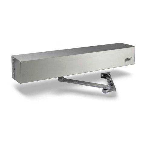
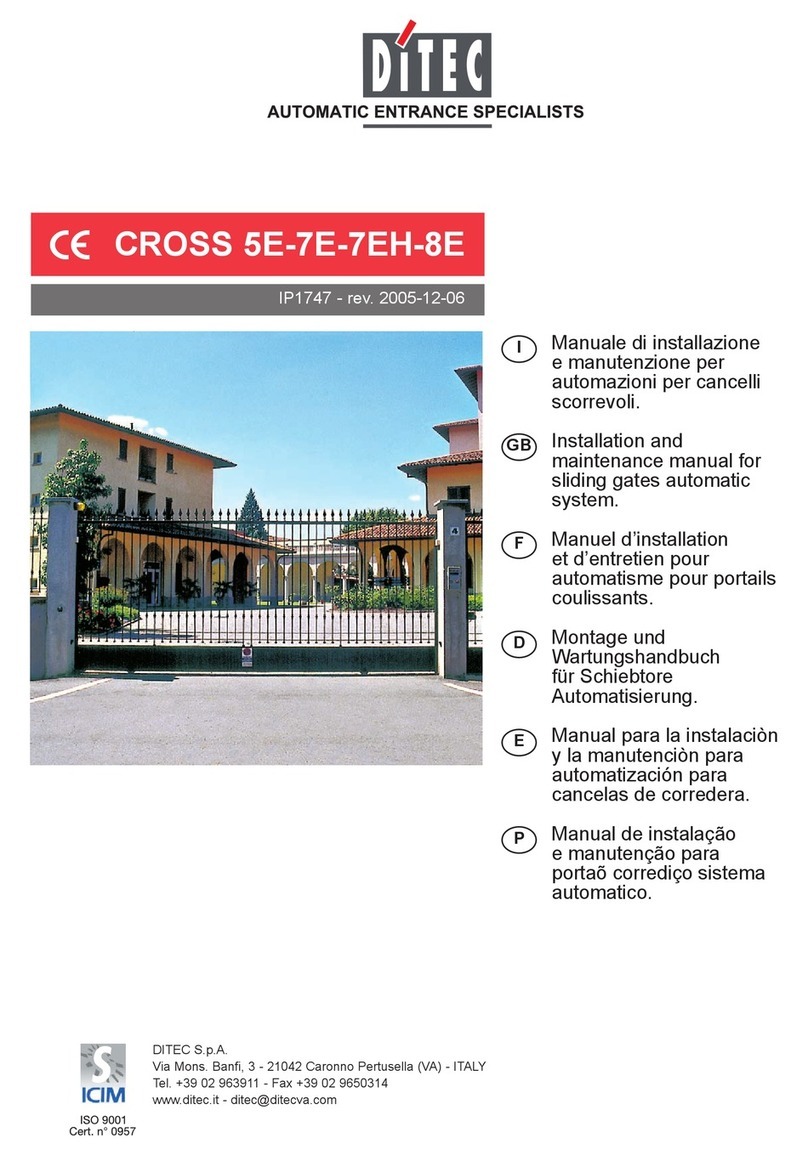
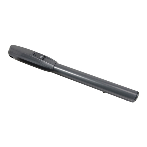
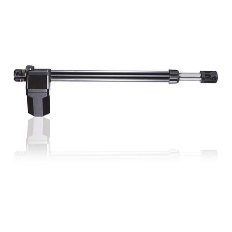
DITEC ION4 User manual

Ditec ION4-ION6
Sliding gates
(translation of the original instructions)
Technical manual
IP2282EN•2023-09-07
Last version of this manual
www.ditecautomations.com

2
IP2288EN
Key
This symbol indicates useful information for the correct functioning of the product.
This symbol indicates instructions or notes regarding safety, to which special atten-
tion must be paid.
Contents
General safety precautions .......................................................................................................................................... 3
Declaration of incorporation of partly completed machinery ...................................................................................... 4
UK Declaration of Conformity ...................................................................................................................................... 5
1. Caractéristiques techniques............................................................................................................................ 6
1.1 Operating instructions .............................................................................................................................................7
1.2 Machinery Directive..................................................................................................................................................7
2. Standard installation ....................................................................................................................................... 8
3. Dimensions...................................................................................................................................................... 9
4. Main components............................................................................................................................................. 9
5. Installation....................................................................................................................................................... 10
5.1 Preliminary checks ..................................................................................................................................................10
5.2 Base plate position...................................................................................................................................................10
5.3 Gearmotor installation.............................................................................................................................................11
5.4 Rack installation.......................................................................................................................................................12
5.5 Operation with virtual encoder ................................................................................................................................12
5.6 Installation of optional accessories.........................................................................................................................13
5.6.1 Magnetic limit switches...................................................................................................................................................13
6. Electrical connections ..................................................................................................................................... 14
7. LCU48 card....................................................................................................................................................... 15
7.1 ION4-6 parallel installation layout ..........................................................................................................................16
8. Using of the menus.......................................................................................................................................... 17
8.1 Switching the display ON and OFF ..........................................................................................................................17
8.2 Navigation keys ........................................................................................................................................................17
8.3 Menu map.................................................................................................................................................................18
9. Product start-up .............................................................................................................................................. 20
9.1 WZ configuration wizard menu................................................................................................................................20
10. Commands....................................................................................................................................................... 22
10.1 SOFA1-SOFA2 or GOPAVRS self-controlled safety edge ........................................................................................23
11. Outputs and accessories.................................................................................................................................. 23
12. Jumper setting ................................................................................................................................................ 24
13. Adjustments..................................................................................................................................................... 25
13.1 Main menu................................................................................................................................................................25
13.2 Second level menu - AT (Automatic Configurations)..............................................................................................26
13.3 Second level menu - BC (Basic Configurations).....................................................................................................27
13.3.1 Additional BC level parameters that can be configured (available with → enabled).................................28
13.4 Second level menu - BA (Basic Adjustment) ..........................................................................................................29
13.4.1 Additional BA level parameters that can be configured (available with → enabled)................................30
13.5 Second level menu - RO (Radio Operations)........................................................................................................... 32
13.5.1 Additional RO level parameters that can be configured (available with → enabled).......................... 33
13.6 Second level menu - SF (Special Functions)...........................................................................................................34
13.6.1 Additional SF level parameters that can be configured (available with → enabled) .................................35
13.7 Second level menu - CC (Cycles Counter) ..............................................................................................................36
13.7.1 Additional CC level parameters that can be configured (available with → enabled).................................37
13.8 Second level menu - EM (Energy Management).....................................................................................................37
13.8.1 Additional EM level parameters that can be configured (available with → enabled) ................................38
13.9 Second level menu - AP (Advanced Parameters)...................................................................................................38
13.9.1 Additional AP level parameters that can be configured (available with → enabled).................................40
14. Signals visualised on the display..................................................................................................................... 42
14.1 Display of automation status...................................................................................................................................42
14.2 Display of safety devices and commands................................................................................................................44
14.3 Visualisation of alarms and faults...........................................................................................................................45
15. Troubleshooting............................................................................................................................................... 48

3
IP2288EN
General safety precautions
This installation manual is intended for qualified personnel only • Installation, electrical connections
and adjustments must be performed by qualified personnel, in accordance with Good Working
Methods and in compliance with the current regulations • Read the instructions carefully before
installing the product. Wrong installation could be dangerous • Before installing the product, make
sure it is in perfect condition.
The packaging materials (plastic, polystyrene, etc.) should not be discarded in the environment
or left within reach of children, as they are a potential source of danger • Do not install the
product in explosive areas and atmospheres: the presence of inflammable gas or fumes represents
a serious safety hazard • Make sure that the temperature range indicated in the technical speci-
fications is compatible with the installation site • Before installing the motorization device, make
sure that the existing structure, as well as all the support and guide elements, are up to standards
in terms of strength and stability. Verify the stability and smooth mobility of the guided part, and
make sure that no risks of fall or derailment subsist. Make all the necessary structural modifications
to create safety clearance and to guard or isolate all the crushing, shearing, trapping and general
hazardous areas • The motorization device manufacturer is not responsible for failure to observe
Good Working Methods when building the frames to be motorized, or for any deformation during
use • The safety devices (photocells, safety edges, emergency stops, etc.) must be installed taking
into account the applicable laws and directives, Good Working Methods, installation premises,
system operating logic and the forces developed by the motorized door or gate • The safety devices
must protect against crushing, cutting, trapping and general danger areas of the motorized door
or gate. Display the signs required by law to identify hazardous areas • Each installation must
bear a visible indication of the data identifying the motorized door or gate • Before connecting the
power supply, make sure the plate data correspond to those of the mains power supply. An omnipolar
disconnection switch with a contact opening distance of at least 3 mm must be fitted on the mains
supply. Check that there is an adequate residual current circuit breaker and a suitable overcurrent
cutout upstream of the electrical installation in accordance with Good Working Methods and with
the laws in force • When requested, connect the motorized door or gate to an effective earthing
system that complies with the current safety standards • Before commissioning the installation
to the end user, make sure that the automation is adequately adjusted in order to satisfy all the
functional and safety requirements, and that all the command, safety, and manual release devices
operate correctly.
During maintenance and repair operations, cut off the power supply before opening the
cover to access the electrical parts • The protection cover of the operator must be removed
by qualified personnel only.
The electronic parts must be handled using earthed antistatic conductive arms. The manu-
facturer of the motorization declines all responsibility if component parts not compatible with
safe and correct operation are fitted • Only use original spare parts for repairing or replacing prod-
ucts • The installer must supply all information concerning the automatic, manual and emergency
operation of the motorized door or gate, and must provide the user with the operation and safety
instructions.
ATTENTION! Important safety instructions.Please follow these instructions carefully.
Failure to observe the information given in this manual may lead to severe personal injury or
damage to the equipment.Keep these instructions for future reference.
This manual and those for any accessories can be downloaded from www.ditecautomations.com

4
IP2288EN
Declaration of incorporation of partly completed machinery
(Directive 2006/42/EC, Annex II-B)
We,
ASSA ABLOY Entrance Systems AB
Lodjursgatan 10
SE-261 44 Landskrona
Sweden,
declare, under our sole responsibility, that the type of equipment with the name:
Ditec ION4-6 automation for swing gates
Complies with the following directives and their amendments:
2006/42/EC Machinery Directive (MD), regarding the following essential health and safety require-
ments: 1.1.2, 1.1.3, 1.2.1, 1.2.2, 1.2.3, 1.2.4.2, 1.2.6, 1.3.9, 1.4.3, 1.7.2, 1.7.3, 1.7.4, 1.7.4.1,
1.7.4.2.
2014/30/EU Electromagnetic Compatibility Directive (EMCD)
2014/53/EU Radio Equipment Directive (RED)
2011/65/EU Restriction of Hazardous Substances (RoHS 2)
2015/863/EU Restriction of Hazardous Substances (RoHS Amendment 2)
Harmonised European standards which have been applied:
EN 61000-6-3:2007 + A1:2011 + AC:2012 EN 61000-6-2:2019
EN 60335-1:2012 + AC:2014 + A11:2014 + A13:2017 + A1:2019 + A14:2019 + A2:2019 + A15:2021
EN 60335-2-103:2015
EN 62233:2008 + AC:2008 EN ISO 13849-1:2015
ETSI EN 300 220-2 V3.2.1 ETSI EN 300 220-1 V3.1.1
ETSI EN 301 489-1 V2.2.3 ETSI EN 301 489-3 V2.1.1
Other standards or technical specifications which have been applied:
IEC 60335-1:2010 + C1:2010 + C2:2011 + A2:2013 + C1:2014 + A2:2016 + C1:2016
IEC 60335-2-103:2006 + A1:2010 EN 12453:2017
The manufacturing process guarantees that the equipment complies with the technical docu-
mentation.
Do not put equipment into service until the installed finished Automatic Entrance System has been
declared compliant with Directive 2006/42/EC on Machinery.
Responsible for the technical documentation:
Matteo Fino
Ditec S.p.A.
Largo U. Boccioni, 1
21040 Origgio (VA)
Italy
Signed on behalf of ASSA ABLOY Entrance Systems AB by:
Place Date Signature Position
Origgio 2023-09-07 Matteo Fino CEO Ditec
© ASSA ABLOY, All rights reserved

5
IP2288EN
UK Declaration of Conformity
We:
ASSA ABLOY Entrance Systems AB
Lodjursgatan 10
SE-261 44 Landskrona
Sweden
Declare under our sole responsibility that the types of equipment with names:
Ditec ION4-6 automation for swing gates
Complies with the following directives and their amendments:
• Supply of Machinery (Safety) Regulations 2016
• Electromagnetic Compatibility Regulations 2016
• Radio Equipment Regulations 2017
• The Restriction of the Use of Certain Hazardous Substances in Electrical and Electronic Equip-
ment Regulations 2012 (RoHS)
Harmonized European standards that have been applied:
EN 61000-6-3:2007 + A1:2011 + AC:2012 EN 61000-6-2:2019
EN 60335-1:2012 + AC:2014 + A11:2014 + A13:2017 + A1:2019 + A14:2019 + A2:2019 + A15:2021
EN 60335-2-103:2015
EN 62233:2008 + AC:2008 EN ISO 13849-1:2015
ETSI EN 300 220-2 V3.2.1 ETSI EN 300 220-1 V3.1.1
ETSI EN 301 489-1 V2.2.3 ETSI EN 301 489-3 V2.1.1
Other standards or technical specifications that have been applied:
IEC 60335-1:2010 + C1:2010 + C2:2011 + A2:2013 + C1:2014 + A2:2016 + C1:2016
IEC 60335-2-103:2006 + A1:2010 EN 12453:2017
The manufacturing process ensures the compliance of the equipment with the technical file.
Responsible for technical file:
Matteo Fino
Ditec S.p.A.
Largo U. Boccioni, 1
21040 Origgio (VA)
Italy
Signed for and on behalf of ASSA ABLOY Entrance Systems AB by:
Place Date Signature Position
Origgio 2023-09-07 Matteo Fino CEO Ditec
© ASSA ABLOY, All rights reserved

6
IP2288EN
Ditec ION4 Ditec ION4J Ditec ION6 Ditec ION6J
Maximum stroke 12 m
Maximum gate weight 400 kg 600 kg
Gate speed 0,1÷0,3 m/s
Thrust 200 N nominaux, 600 N de démarrage 300 N nominaux, 800 N de démarrage
Power supply 230 V~ 50/60 Hz 120 V~ 50/60 Hz 230 V~ 50/60 Hz 120 V~ 50/60 Hz
Power absorption 0,45 A 0,9 A 0,6 A 1,2 A
Fuse T1A F2A F1,6A F3,15A
Power 100 W 130 W
Service class FRÉQUENT
(testé jusqu’à 150.000 cycles)
Intermittence S2= 30 min (T= 25°C)
S3= 60% (T= 25°C)
Cycles / day *800 (T= 25°C)
Continuous cycles *30 (T= 25°C)
Lifespan De 50 000 à 150 000 cycles en fonction des conditions reportées dans le tableau (voir
instructions complètes).
Usage temperature (T) ( with active NIO)
-20°C +55°C -35°C +55°C
Degré de protection IP44
Motor output 24V 10A max
Power supply to
accessories 24V 0,3A max
Control panel LCU48
Radio frequency
433,92 MHz
(cod. ZENRS)
868,35 MHz
(cod. ZENPRS)
ZENRS receiver module included, ZENPRS
optional
Storable radio codes 100= ( → → / )
200= ( → → / )
Noise level LPA ≤70 dB (A)
*Indicative cycles considering a 6 m wing and factory settings (default speed of 20 cm/s). ION4 / ION6 allows a
maximum speed of 30 cm/s (configurable). A cycle is considered an opening followed by a closing.
1. Caractéristiques techniques

7
IP2288EN
Example of lifespan calculation for ION4
Gate wing weight>150Kg 10
Gate wing width> 4.5m 10
Dust 10
Safety edges installed 10
VA/VC > default 10
Total stress index 50
Estimated lifespan - 80,000 cycles
Estimated daily cycles 22 (for 10 years)
0
10
20
30
40
50
60
70
80
90
100
0
10.000
indice di gravosità
20.000
30.000
40.000
50.000
60.000
70.000
80.000
90.000
100.000
110.000
120.000
130.000
140.000
150.000
cicli
Index of conditioning factors
ION4 ION6
Gate wing weight
>150Kg 10 -
>200Kg 20 10
>300Kg 30 20
>400Kg - 30
Gate wing width >4m 20 10
>8m - 20
Wheel diameter <100mm 10
Saline environment 10
Safety edge installed 10
R1/R2 > default 10
VA/VC > default
OC/CB < default 10
0
10
20
30
40
50
60
70
80
90
100
0
10.000
indice di gravosità
20.000
30.000
40.000
50.000
60.000
70.000
80.000
90.000
100.000
110.000
120.000
130.000
140.000
150.000
cicli
Index of conditioning factors
cycles
cycles
1.2 Machinery Directive
According to the Machinery Directive (2006/42/EC), the installer who motorises a door or gate has
the same obligations as the manufacturer of a machine, and as such must:
- prepare the technical documentation, which must contain the documents indicated in Annex V
of the Machinery Directive;
(the technical documentation must be kept and made available to the competent national
authority for at least ten years, starting from the date of construction of the motorised door);
- draw up the EC statement of conformity according to Annex II-A of the Machinery Directive and
hand it over to the customer;
- affix the CE marking to the motorised door in accordance with point 1.7.3 of Annex I of the
Machinery Directive.
1.1 Operating instructions
Use: FREQUENT for condominium, industrial and commercial, car park entrances with heavy
driveway or pedestrian use.
- The class of service, usage times and number of consecutive cycles are suggestions. They are
statistically measured under average usage conditions and cannot be certain for every single case.
- For each automatic entrance, there are variables such as friction, balancing and environmental
conditions that can substantially change the operating life and quality of the automatic entrance
or some of its components (including the automated mechanisms). It is up to the installer to
implement safety factors appropriate for each particular installation.

8
IP2288EN
2. Standard installation
5
A
6
3
7
5
8
1
5
5
4
2
Ref. Code Description Cable
1 Ditec ION4 - ION6 Actuator ION with control panel
3G x 1.5 mm²
A
Connect the power supply to a type-approved omnipolar switch, with a contact
opening distance of at least 3mm (not supplied). See chapter 6.
The connection to the mains must follow an independent path, separate from the
connections to the control and safety devices.
2 ZEN Transmitter /
3
FLM
FL24
Flashing light 2 x 1 mm²
Antenna (integrated in the flashing light) RG-58 coax
cable (50 Ω)
4
AXK4 Digital combination wireless keypad /
AXK5M
AXK5N
AXK5NM
AXK5NI
Wall-mounted key-operated selector switch with European cylinder
Semi-recessed key-operated selector switch with European cylinder
Wall-mounted key-operated selector switch without cylinder
Semi-recessed key-operated selector switch without cylinder
4 x 0.5 mm²
AXR7 RFID reader unit 5 x 0.5 mm²
5
LIN2
LIN2B
AXP2
LAB4
Photocells 4 x 0.5 mm²
6
SOFAP20
SOF2M20-SOF3M20
SOFA15-SOFA20-
SOFA25
Safety edge
2 x 0,5 mm² min
7 GOPAV Radio system for sensitive edges /
8 LAB9 Magnetic loop 2 x 1,5 mm²

9
IP2288EN
Ref. Descripción
1Motor
2Control panel
3Key release
4Pinion
5Cable inlet
6Power supply terminal and fuse
3. Dimensions
4. Main components
260
300
80
195
15540
1
3
2
6
4
5

10
IP2288EN
5.1 Preliminary checks
Check the stability of the wing (derailing and lateral falls) and the sliding wheels and that the upper
guides do not cause any friction.
The sliding guide must be securely fixed to the ground for the full length within doorway and must
have no irregularities that could hinder the movement of the wing.
The opening and closing stops must be fitted.
If the gate has slits, make sure they are covered to prevent shearing points or install active safety
edges on the columns.
Safety device should be installed at the end of the wing to reduce the collision force.
WARNING:
•Make sure that the gate can not exit the sliding guides and fall.
•Make sure that the protection system and any manual release function correctly.
5. Installation
The given operating and performance features can only be guaranteed with the use of DITEC ac-
cessories and safety devices.
Unless otherwise specified, all measurements are expressed in mm.
5.2 Base plate position
Make a concrete base with the anchor ties and base plate embedded, which must be level and
clean and of the size indicated in the figure.
NOTE: if the concrete base has already been made, base plate can be fixed using M8
plugs (not supplied).
OPENING
160
X+20 [*]
40
min
Ø80 90°
220
260
[*] CROSSCRN2
[*] CROSSCRI
X=40
M12
low type

11
IP2288EN
- Release the gearmotor [1] (see OPERATING INSTRUCTIONS). Loosen the front screw [2] and
remove the casing by pressing on its sides [3-4].
- Place the gearmotor on the base plate.
- Adjust thegearmotor horizontallyby sliding italongthe slotsof thegearmotor base andverticallywith
four levelling screws [A].
NOTE: during the vertical adjustment, keep the gearmotor slightly raised from the base plate
so that the rack can be fixed and subsequent adjustments are possible.
- After adjusting, fix the gearmotor using screws [B].
5.3 Gearmotor installation
WARNING: The gearmotor must be suitably raised from the ground to avoid flooding.
Tighten the [B] screws using a tightening torque of 20-25 Nm.
3
3
2
4
1
X
100
±5
AB
-5 +20

12
IP2288EN
- Release the gearmotor (see OPERATING INSTRUCTIONS) and open the gate.
- Place the rack against the pinion and sliding the gate manually fix it along its whole length.
NOTE: To make it easier to align the rods correctly, use a scrap piece of rack and rest it under-
neath the junction point, as shown in the figure detail.
- Once fixed, vertically adjust the gearmotor to give a play of about 2 to 3 mm between the pinion
and the rack.
- Secure the gearmotor with the [B] screws using a tightening torque of 20-25 Nm.
- Slightly lubricate the rack and pinion after assembly.
Manually check that the gate slides evenly and without friction.
5.4 Rack installation
5.5 Operation with virtual encoder
ION4-ION6 gearmotors do not require limit switches because they have a virtual encoder.
Mechanical opening and closing end stops must be installed.
The gate automatically slows when approaching the end stops.
WARNING: when the gate reaches the opening or closing limit stop, it reverses briefly to facilitate
manual release of the gearmotor.
min.80
2÷3

13
IP2288EN
5.6 Installation of optional accessories
For installation of the battery kit, refer to the SBU-IONSBU-BBU20-BBU65 (IP2254) manual.
For installation of the remote release handle, refer to the IONSBM and ASR2 manual.
For the installation of the limit switch kit, refer to the NES100FCM manual.
To position the limit switches, you can use the menu → (visible by activating the additional
configurations → ).
The display shows the status of the limit switches:
• : opening limit switch configured and activated;
• : closing limit switch configured and activated;
• (both parts of display active): opening limit switch not configured and activated;
• (no part of display active): closing limit switch not configured and activated;
• (central part of display active): no limit switch activated.
With the limit switches configured as STOP (FA= SX; FC= SX) the anti-violation function is activated.
When the automation stopped open or closed, if the gate backs off releasing the limit switch, it is
brought back into position avoiding openings from external forces [energy saving must be disabled
ES= OFF].
The limit switch kit is used to stop the gate before it reaches the opening and closing
mechanical stops.
With a limit switch installed, slowdown is carried out at regulated power to overcome
possible friction.
The battery kit guarantees operation if there is a power cut.
For advanced control of battery-powered operation, refer to the EM menu.
The kit can be used to remotely release the gearmotor.
A microswitch guarantees safety.
When the handle is released, the control panel performs a reset
5.6.1 Magnetic limit switches
5.6.2 Battery kit
5.6.3 Remote release handle

14
IP2288EN
6. Electrical connections
A
A
B
B
Before connecting the power supply, make sure that the data on the plate correspond to
the electricity distribution network data. Provide an omnipolar switch/disconnector on the
power network with a contact opening distance of 3 mm or more. Check that there is a suitable
residual-current device and surge protector upstream of the electrical system. Use an H05RN-F
3G1.5 electrical cable and connect it to terminals L (brown) and N (blue) inside the automation
system. Connect the earth cable (yellow/green) to the earth terminal.
Secure the cable by means of the cable clamp and only unsheathe it at the terminal.
Connections to the electrical distribution network and any other low-voltage conductors (230
V), in the section outside the automation system, must be made with corrugated pipes that are
independent and separate from the path of connections to the control and safety devices (SELV=
Safety Extra Low Voltage). Make sure there are no sharp edges that could damage the power cord.
ATTENTION: always observe L-N polarity when connecting to the mains and close all
unused clamps.
Ensure that the mains connection cables, any other low-voltage cables (230 V), and
safety extra-low voltage safety accessory connection cables in the portion located in-
side the product are kept well separated from the gear motor body.

15
IP2288EN
+-LP 30
LSW
M+ M-
520 0168
C
O
M
SCHEDA AD INNESTO
AUX
UPDOWNENTERESC
RADIO RX
ZENRS
ZENPRS
JR1
JR5
130
24V~
Trasformatore
Alimentazione
Fusibile
Motore
SSW
Lampeggiante
NES100FCM
Finecorsa
Passo-passo
Apertura parziale
-
+
Uscita 24 V
Antenna
Arresto di sicurezza
Sicurezza in chiusura
Microswitch
di sblocco
24V
LN
CARICA
BATTERIE
(SBU)
BAT
7. LCU48 card
Power supply
Flashing light
Step-by-step
Partial opening
24V output
Safety stop
Closing safety device
Antenna
Transformer Fuse
Release
microswitch
Limit switch
NES100FCM
Motor
PLUG-IN BOARD
BATTERY
CHARGER
(SBU)

16
IP2288EN
7.1 ION4-6 parallel installation layout
+-
LP 30
LSW
BATTERY
CHARGE
(SBU)
M+ M-
520 0168
C
O
M
AUX
UPDOWN
BAT
Flashing light
ENTERESC
RDX
ZENRS
ZENPRS
JR1
JR5
130
24V~
POWER
Fuse
SSW
NES100FCM
limit switch
release
microswitches
Transformer
M 24 V
LN
Step-by-step
Partial opening
24 V output
Safety stop
Closing safety device
Antenna
+
A
ZENRS
ZENPRS
+-
LP 30
LSW
BATTERY
CHARGE
(SBU)
M+ M-
520 0168
C
O
M
AUX
UPDOWN
BAT
Flashing light
ENTERESC
RDX
JR1
JR5
130
24V~
POWER
Fuse
SSW
NES100FCM
limit switch
release
microswitches
Transformer
M 24 V
LN
Step-by-step
Partial opening
24 V output
Safety stop
Closing safety device
Antenna
+
B
BIXR2
BIXPR2
MEM
BIXMR2
BIXMR*
PRG
SIG OUT1 OUT2
MOD CHN
ANT
ML
1
2
3
4
1
2
3
4
MS
OUT1
OUT2
MOD= OFF
CHN= CH1
CNONC
OPENING OPENING
A
RX
RX
RX
TX TX
TX
B
TX
RX
Set AC and C5 parameters as follows:
•
x 2 s
• x 2 s
NOTE: available with → active.

17
IP2288EN
The procedure to switch on the display is as follows:
• press the ENTER key
• the display functioning check starts
• the first level menu is displayed
The procedure to switch off the display is as follows:
• press the ESC key
NOTE: there is no automatic exit from the WZ quick configuration menu. For all the other menus,
the display switches off automatically after 60 seconds of inactivity.
8.1 Switching the display ON and OFF
8. Using of the menus
NOTE: pressure on the keys may be quick (less than 2 s) or prolonged (longer than 2 s).
Unless specified otherwise, quick pressure is intended.
To confirm the setting of a parameter, prolonged pressing is necessary.
• The simultaneous pressing of the ↑ and ENTER keys produces an opening command.
• The simultaneous pressing of the ↓and ENTER keys produces a closing command.
• The simultaneous pressing of the ↑ and ↓ keys produces a POWER RESET command (power
supply interruption and automation restart).
• Keep the UP ↑ or DOWN ↓ key pressed to begin fast menu scrolling.
To set a parameter, select the desired value and press ENTER for 2 seconds to save.
Example: setting of 30 seconds for parameter TC
x 2 s
• In some menus, the parameter measurement unit can be viewed by pressing the ENTER key
once the value has been displayed.
8.2 Navigation keys

18
IP2288EN
8.3 Menu map
Standard settings
*
*
Opening direction
RT= right
LF= left
Contact 1-5 command
operation
Automatic closure
enabling
Automatic clos-
ing time
Gate weight
Gate length
Opening
speed
Closing speed
Selection of device con-
nected to terminals 1-6
Selection of device con-
nected to terminals 1-8
Radio receiver
operation
Setting of radio coded
messages
Remote control
storage
Confirm configura-
tion
Quick configuration menu
Opening direction
RT= right
LF= left
Reset general
settings
Activation of advanced
parameters menu
Residential 0
Residential 1
Condominium 0
Automatic closure
enabling
Automation status
at switch-on
Reversal safety
operation
Activation of anti-
freeze system NIO
Contact 1-5 command
operation
Activation of "operator
present" function
Radio receiver
operation
AUX1 board
operation
Start-up at maxi-
mum power
Setting of step-by-step
sequence via com-
mand 1-5
Duration of STOP in
step-by-step sequence
via command 1-5
Operation of safety
stop/closure com-
mand
Automatic configurations
Standard adjustments
Automatic closing
time after partial
opening
Thrust adjustment on
obstacles and opening
current
Opening
speed
Closing speed
Automatic clos-
ing time
Partial opening measure-
ment adjustment
Thrust adjustment on
obstacles and closure
current
Obstacle recognition
time adjustment
Start-up time
adjustment
Adjustment of acceleration
time on opening
Adjustment of acceleration
time on closure
Deceleration time adjust-
ment during opening
Deceleration distance on
opening
Deceleration time adjust-
ment during closure
Deceleration distance on
closing
Adjustment of approach
speed during opening
Adjustment of approach
speed during closure
Obstacle detection limit
during opening
Initial movement
speed
Function of output
+LP-
Electric lock release time
Obstacle detection limit
during closure
Remote control
storage
Visualisation of number of
remote controls stored
Wireless
operations

19
IP2288EN
Additional configurable pa-
rameters available with
AT → AA enabled.
*
*
Firmware update
*
*
*
*
Setting of memory opening
via remote control
Setting of radio coded
messages
Maximum number of
remote controls that can
be stored in the integrated
memory
Menu navigation via remote
control keypad
Selection of function CH1 of
the stored remote control
Selection of function CH2 of
the stored remote control
Selection of function CH3 of
the stored remote control
Selection of function CH4 of
the stored remote control
Deletion of a remote control
Total memory
deletion
Control panel firmware
version
Configuration storage
Configuration loading
Password setting
Password insertion
Deletion of user settings
Loading of last configura-
tion set
Alarm counter
Alarm log
Special functions
Alarm reset
Motor current visu-
alisation
Visualisation of maximum
and minimum tempera-
tures recorded
Limit switch test. Visual-
ises FA/FC only (N.O. / NO
if they are not configured)
Total number of
operations
Partial number of
operations
Power supply hours
Power supply hours
via battery
Maintenance alarm
setting
Visualisation of mainte-
nance alarm mode
Reset of partial operations
counter
Power supply via solar
panels
Energy saving
Signal for batteries
almost flat
Voltage threshold for indi-
cating when the batteries
are almost flat
Battery mode
Selection of opening
limit switch mode
Selection of closure
limit switch mode
Selection of device con-
nected to terminals 1-6
Selection of device con-
nected to terminals 1-8
Configuration of input 1-9
Selection of device con-
nected to terminals 1-6
and 1-8
Switch-on time for
independently commanded
courtesy light
Fixed partial opening
Display mode
Partial opening com-
mand of terminal 1-20
Courtesy light switch-on
time
Duration of disengagement
after edge intervention
Duration of disengagement
on stop during opening
Duration of disengagement
on stop during closure
Selection of type of
obstacle
Stroke estimate correction
NIO intervention tempera-
ture and automatic ramps
Selection of operating
mode for device connected
to terminals 1-6
Visualisation of internal
panel temperature
Automatic ramp adjust-
ment
High temperature protec-
tion enable
Setting pre-flashing time
on opening
Adjustment of approach
speed during closure
Renew automatic closing
time after safety device
release
Learning speed setting
Cycle countersEnergy management
Advanced parameters
Compatibility setting with
older generation GOL4 re-
mote controls

20
IP2288EN
9. Product start-up
9.1 WZ configuration wizard menu
for 2 sec.
To access the WZ configuration wizard menu:
Hold down the ENTER button for 2 seconds.
When OK has stopped flashing, DM, the first menu parameter, is displayed.
For rapid configuration of the product, use the WIZARD (WZ) menu or the second level AT (Automatic
Configurations) menu [See par. 13.2].
For detailed, customised configuration, use the main menus BC, BA, RO, SF, CC, EM, AP.
To set a parameter:
1. Press ENTER to access the configuration items.
2. Scroll UP/DOWN the possible options.
3. To confirm, press the ENTER button for 2 seconds. The selected value flashes and when it has
finished, the next parameter appears.
for 2 sec.
WZ - Wizard
Display Description
DM
- Selection of opening direction (looking at the automation from the side being examined)
• RT: opens to the right (default)
• LF: Opens to the left
C5 - Operation of command associated with contact 30-5
• 1-5: step-by-step (default)
• 1-3: Opening
AC - Enabling of automatic closure
• ON: enabled (default)
• OF: disabled
TC - Setting of automatic closing time [seconds]
[NOTE: only visible if you have selected AC = ON in the previous step]
• from 0” to 59” with intervals of 1 second.
• - from 1’ (default) to 2’ with intervals of 10 seconds.
GW - Selection of gate weight
The selected value sets parameters R1 and R2 to adjust the maximum thrust current of the
motor.
• LG: up to 200 kg → (R1=R2=30%)
• MG: between 200 kg and 300 kg for ION4 and ION4J, between 200 kg and 400 kg for ION6
and ION6J → (R1=R2=50%) (default)
• HG: between 300 kg and 400 kg for ION4 and ION4J; between 400 kg and 600 kg for ION6
and ION6J → (R1=R2=70%)
GL - Selection of gate length
The selected value sets parameters OB and CB for adjusting the deceleration space
• 02: between 0 and 2 m → (OB=CB=50cm)
• 04: between 2 and 4 m → (OB=CB=60cm) (default)
• 06: between 4 and 6 m → (OB=CB=70cm)
• >6: over 6 m → (OB=CB=80cm)
VA - Selection of opening speed
• LO: 15 cm/s
• ME: 20 cm/s (default)
• HI: 25 cm/s
Other manuals for ION4
1
This manual suits for next models
3
Table of contents
Other DITEC Garage Door Opener manuals