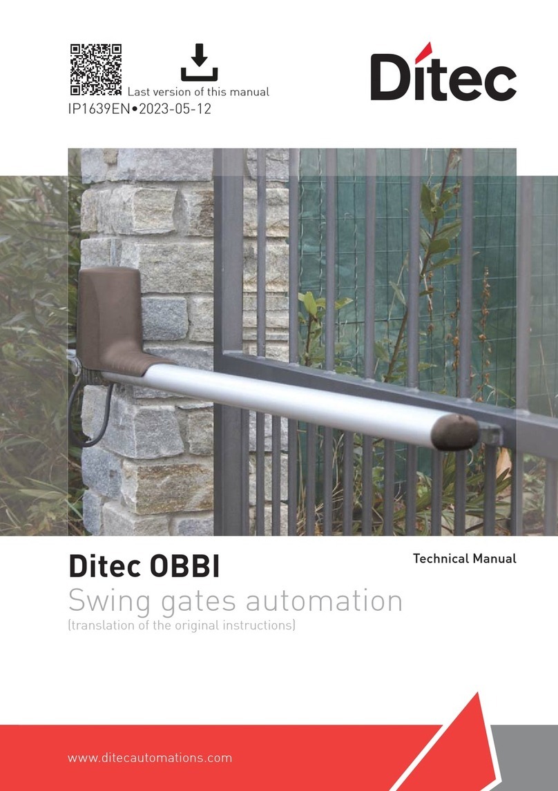
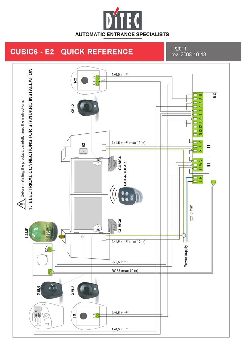
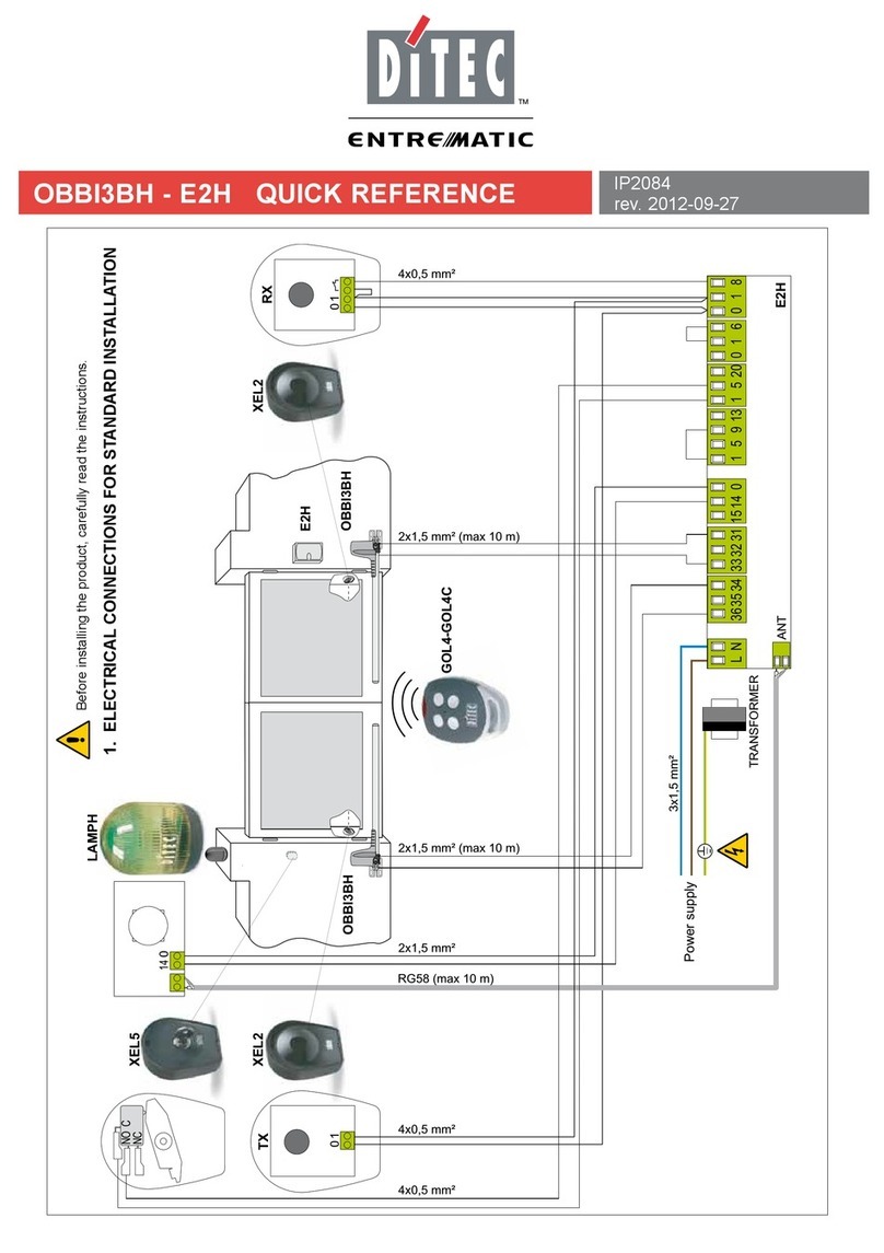
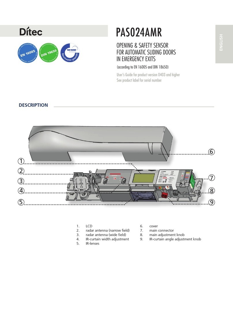
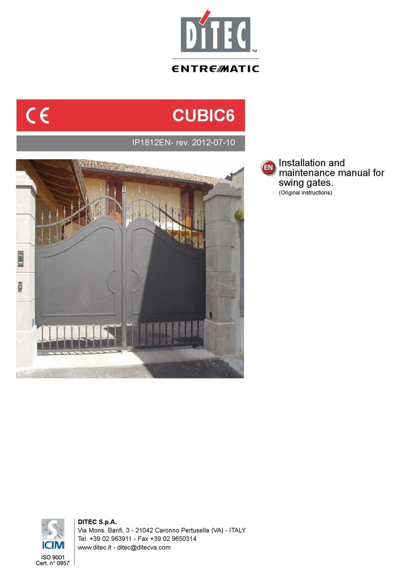
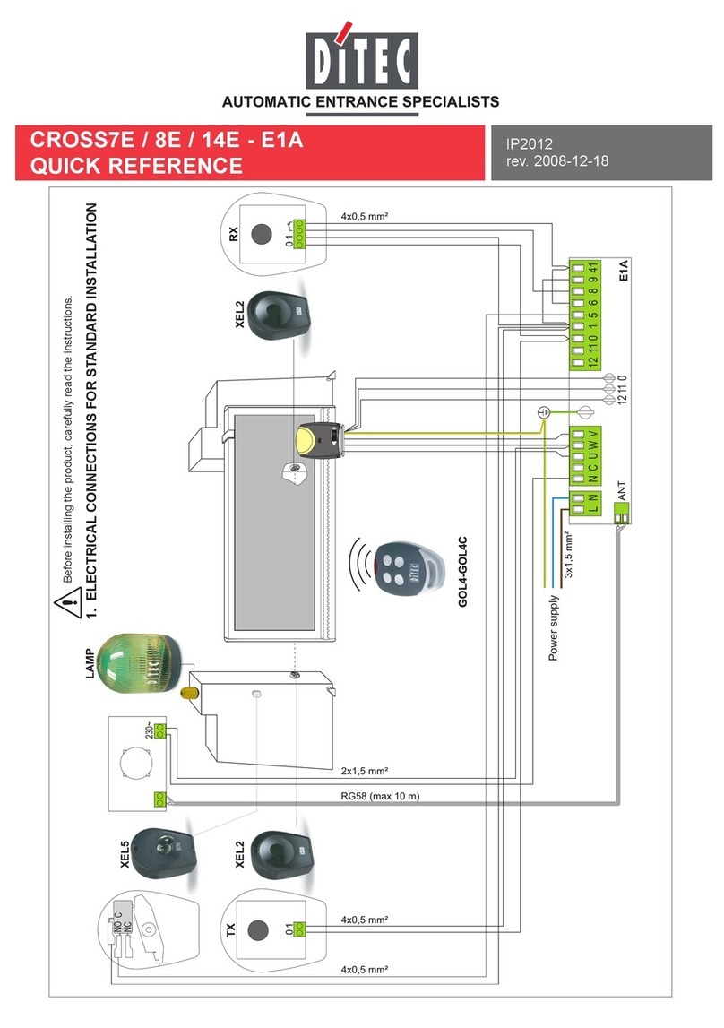
DITEC PasM24T User manual

1/8
PASM24T
ISTRUZIONI PER L’USO
RILEVATORE DI MOVIMENTO AUTO-SORVEGLIATO
PER PORTE AUTOMATICHE DI USCITA DI SICUREZZA
Tecnologia : Iperfrequenza e
microprocessore
Frequenza emessa : 24.175 GHz
Potenza emessa : <20 dBm EIRP
Densità di potenza emessa : < 5 mW/cm²
Altezza d’installazione
Standard :1.8 m a 3 m
Alta : 3 m a 4 m
Angolo d’inclinazione : 0° à 90° in senso verticale
-30° à + 30° in senso
laterale
Area di rilevazione (altezza d’installazione = 2.2 m)
Area di rilevazione larga : 4m (L) x 2m (P)
Area di rilevazione stretta : 2m (L) x 2.5m (P)
Modo di rilevazione : Movimento
Velocità min. di rilevazione : 5 cm/s (misurata nell’asse
del radar)
Tensione d’alimentazione : 12V a 24V AC ±10%
12V a 24V DC +30%/ -10%
Frequenza della rete di
alimentazione
:50 à 60 Hz
Consumo : < 2W (VA)
Configurazione « output » in modo di « non detezione »
(fonte corrente ON)
Tensione max. circuito-
aperto
: 6.5V
Voltaggio di « output »
disponibile a 10mA
: 3V min.
Carica tipo : fino a 3 opto-combinatore
collegati in serie. Libero di
potenziale.
Configurazione « output » in modo « detezione » (fonte
corrente OFF)
Corrente di fuga : < 100µA
Tensione rimanente
del circuito-aperto
: < 500mV
Durata del contatto in
uscita
:0.5 s a 9s (regolabile)
Gamma di temperature :-20°C a +55°C
Grado di protezione : IP54
Conformità alle norme : R&TTE 1999/5/EC; EMC 89/336/EEC
Dimensioni : 120 mm (L) x 80 mm (H) x 50 mm (P)
Peso : 0.215 kg
Materia del cofano : ABS
Colore del cofano : Grigio antracite, colore alu o bianco
Lunghezza del cavo : 2.5m
Aggiustamenti manuali
Sensibilità (per pulsanti)
Orientamento dell’ area di rilevazione (meccanicamente)
Forma dell’ area di rilevazione (scelta fra due antenne)
Aggiustamenti con telecomando
Sensibilità
Durata del contatto in
uscita
Modo di rilevazione
Immunità
Altezza d’istallazione
Controllo della porta
Codice di sicurezza
:
:
:
:
:
:
10 livelli (0 a 9)
10 livelli (0.5s a 9s)
uni-/bidirezionale, MTF, reverse
quasi-presenza, normale,
immunità rafforzata
normale, alta
in automatico, aperto permanentemente
codice d’accesso a 1-4 cifre
Morsettiera
Impronte pe
r
il passaggio
del cavo
Antenna planare
lobo stretto
Ricevitore infrarosso
LED
Pulsanti
Orientazione laterale
dell’antenna
Antenna planare lobo largo
(standard)
Orientazione verticale
dell’antenna
Fissare fermamente il
rilevatore in modo che
non vibri.
Il rilevatore non può
essere installato
direttamente dietro di un
pannello né di qualsiasi
materiale.
Togliere ogni oggetto
che potrebbe muoversi
o vibrare nella area di
rilevazione.
Evitare la presenza di
tubi neon nella area di
rilevazione.
Evitare il contatto con le
parti elettroniche
(scariche
elettrostatiche).
DESCRIZIONE
DEL RILEVATORE
CONSIGLI PER
L’INSTALLAZIONE
VISTA DALL’INTERNO COFANO
(VISTA DALL’INTERNO)
SPECIFICHE
TECNICHE

'DOO¶LQGLHWURSULPDGHOO¶LQVWDOOD]LRQH 'DOGDYDQWLGRSRO¶LQVWDOOD]LRQH
x ,QFROODUHODPDVFKHUD
x )RUDUHFRPHLQGLFDWR
x,QVHULUHOHYLWLVHQ]DDYYLWDUOHD
IRQGR
x)DUSDVVDUHLOFDYRQHOO¶DSSRVLWREXFR
x7DJOLDUHXQDGHOOHLPSURQWHSUHYLVWHSHU
IDUFLSDVVDUHLOFDYR
,QVWDOODUHLOULOHYDWRUHHFKLXGHUHOHYLWL/DVFLDUHDOFDYR
XQDOXQJKH]]DVXIILFLHQWHSHUUDJJLXQJHUHODPRUVHWWLHUD 9
$&'&
287 287
ÊSRVVLELOHPRQWDUHTXHVW¶DSSDUHFFKLRDOVRIILWWRDYHQGR
FXUDGLRULHQWDUHODSDUWHVIHULFDGHOULOHYDWRUHLQGLUH]LRQH
RSSRVWDDOODSRUWD2ULHQWDUHO¶DQWHQQDFRQXQDQJROR
YHUWLFDOHGLFLUFD
3HUXQPRQWDJJLRVXOODSDUWH
VXSHULRUHGHOSURILODWR
GHOO¶RSHUDWRUHXWLOL]]DUH
O¶DFFHVVRULR(%$
3HUXQPRQWDJJLRLQFDVWUDWRQHOVRIILWWRXWLOL]]DUH
O¶DFFHVVRULRG¶LQFDVWUR3$60,
3HUXQDPLJOLRUHSURWH]LRQHGDOOD
SLRJJLDXWLOL]]DUHO¶DFFHVVRULRGL
SURWH]LRQH3$60&
$3(5785$'(/
5,/(9$725(
35(3$5$=,21(
'(/
0217$**,2
&2//(*$0(172
(0217$**,2
$/75(
3266,%,/,7¬',
0217$**,2

3/8
A. LA LARGHEZZA DELL’ AREA DI RILEVAZIONE DIPENDE DALL’ANTENNA PLANARE SCELTA
Per un’ area di rilevazione larga,
utilizzare l’antenna a 3 elementi
Per un’ area di rilevazione stretta,
utilizzare l’antenna a 6 elementi
Le aree di rilevazione indicate qui accanto
corrispondono agli aggiustamenti
seguenti :
xOrientazione dell'antenna : 30° ;
xSensibilità : 9 ;
xModo bidirezionale ;
xAltezza d’installazione : 2.2m.
WARNING
The sensor has to be set up in such a way that the detection field depth equals at least 1.5m to ensure the installation is TÜV
compliant.
In addition, a technically trained person has to check at least once year the integrety of the detection.
Togliere l'antenna area
stretta dal suo posto.
Togliere delicatemente l’elemento di fissazione e
l’antenna area larga.
Fissare l’antenna sul supporto
mediante l’elemento di
fissazione.
B. LE DIMENSIONI (LARGHEZZA, PROFONDITÀ, ZONA MORTA) DELL’AREA DI RILEVAZIONE DIPENDONO
DALL’AGGIUSTAMENTO DELLA SENSIBILITÀ (AGGIUSTABILE DA 0 A 9)
Le aree di rilevazione indicate qui accanto
corrispondono agli aggiustamenti seguenti :
xAntenna area larga ;
xOrientazione dell’antenna : 30° ;
xModo bidirezionale ;
xAltezza d’installazione : 2.2m.
C. LE DIMENSIONI (LARGHEZZA, PROFONDITÀ, ZONA MORTA) DELL’AREA DI RILEVAZIONE DIPENDONO DALL’ALTEZZA
D’INSTALLAZIONE (AGGIUSTABILE DA 0 A 9)
Le aree di rilevazione indicate qui accanto
corrispondono agli aggiustamenti seguenti :
xAntenna area larga ;
xOrientazione dell’antenna : 30° ;
xModo bidirezionale ;
xSensibilità : 9
N.B. : Da 3 metri d’altezza in più, è consigliato
utilizzare il modo « installazione alta »” .
Antenna a
3 elementi
Antenna a
6 elementi
AGGIUSTAMENTI
MECCANICI
mm
mm
mm

4/8
D. LA POSIZIONE DELL’ AREA DI RILEVAZIONE DIPENDE DALL’ANGOLO LATERALE DELL’ANTENNA PLANARE
Le aree di rilevazione indicate qui
accanto corrispondono agli
aggiustamenti seguenti :
xAntenna area larga ;
xModo bidirezionale ;
xAngolo laterale dell’antenna :
30°, - 30°
xAltezza d’installazione : 2.2m.
E. LA POSIZIONE DELL’ AREA DI RILEVAZIONE DIPENDE DALL’ANGOLO VERTICALE DELL’ANTENNA PLANARE
Le aree di rilevazione indicate
qui accanto corrispondono agli
aggiustamenti seguenti :
xAntenna area larga ;
xSensibilità : 9 ;
xModo bidirezionale ;
xAltezza d’installazione : 2.2m.
Per l’area di rilevazione la più
vicina alla porta, aggiustare
l’angolo d’inclinazione al minimo
(0° a 15°)
Esempio d’installazione
su un operatore
profondo
Per un’area di rilevazione vicina
alla porta, aggiustare l’angolo
d’inclinazione a 30°
Esempio d’installazione
su un operatore classico
Per un’area di rilevazione lontana
dalla porta, aggiustare l’angolo
d’inclinazione a 45°
Esempio d’installazione
su un operatore classico
(con zona morta)
PER UN MONTAGGIO AL SOFFITTO :
Le aree di rilevazione indicate qui
accanto corrispondono agli
aggiustamenti seguenti :
xAntenna area larga ;
xSensibilità : 9 ;
xModo bidirezionale ;
xAltezza d’installazione : 2.2m.
AGGIUSTAMENTI
MECCANICI
mm
mm

5/8
1. INSERIRE LE BATTERIE
xAprire l’apposito comparto all’indietro dal telecomando ;
xInserire le 2 batterie AAA, fornite nell’imballaggio del telecomando, come indicato qui accanto ;
xChiudere il comparto.
Tasti numero0-9 (1)
Non usato (2)
Tasto Più (3)
Apertura sessione (4)
Tasto Meno (5)
Durata del contatto in uscita (6)
Sensibilità (7)
Modalità di rilevazione (8)
Immunità (9)
(10) Non usato
(11) Non usato
(12) Non usato
(13) Altezza d’istallazione
(14) Controllo della porta
(15) Controllo dei valori
(16) Chiusura sessione
(17) Non usato
(18) Non usato
(19) Setup
(20) Non usato
N.B. : Per un risultato ottimo, puntare il telecomando in direzione
del rilevatore e premere i tasti. Il raggio d’azione è di circa 5
metri con o senza il cofano.
2. CONFIGURAZIONE DEL RILEVATORE
Ogni sessione di aggiustamento con il telecomando ad infrarossi deve obbligatoriamente iniziare con « apertura sessione » e
concludersi con un doppio « chiudere sessione »
La tabella qui sotto fa l’elenco dei parametri configurabili con il telecomando, così come della sequenza logica delle operazioni da
effettuare per aggiustare questi parametri.
PARAMETRI PROCEDURA STATO DELLA LED
APRIRE
SESSIONE Premere il tasto APRIRE SESSIONE (4). Inserire il codice d’accesso a quattro cifra con i
tasti numerici 0 – 9 (1). Il codice d’accesso puo’ essere composto da 1 a 4 cifre (valori di
fabbrica o nessun codice d’accesso: 0 o 0000).
Se è il primo aggiustamento del rilevatore o se il codice d’accesso è tornato all’
impostazione fabbrica "0000" o durante il minuto che segue la messa sotto tensione,
basta premere il tasto APRIRE SESSIONE (4) (nessun codice d’accesso).
APRIRE SESSIONE con codice d’accesso a 4 cifre
APRIRE SESSIONE con codice d’accesso a -4 cifre
APRIRE SESSIONE senza codice d’accesso
La LED rossa lampeggia rapidamente mentre il
radar è in attesa del codice d’accesso.
Una volta il codice d’accesso corretto inserito o
se non ci vuole un codice d’accesso, la LED
lampeggia lentamente per indicare che la
sessione è aperta e che si può dunque procedere
agli aggiustamenti.
N.B. : = Sessione di aggiustamenti attiva
CHIUDERE
SESSIONE
Quando tutti i parametri sono stati aggiustati, premere il tasto CHIUDERE SESSIONE (16).
Se ci vuole un nuovo codice d’accesso, inserire il codice a 4 cifra con i tasti numerici 0-9
nel minuto che segue.
Se non c’è un codice d’accesso o se si vuole conservare il codice d’accesso attuale,
premere una seconda volta il tasto CHIUDERE SESSIONE (16).
La sessione si chiude automaticamente se nessun tasto del telecomando viene premuto
durante 1 minuto.
CHIUDERE SESSIONE cambiando il codice d’accesso
CHIUDERE SESSIONE senza codice d’accesso o
senza cambiarlo
La LED rossa smette di lampeggiare per tornare
al suo funzionamento iniziale.
CONFIGURAZIONE
DEI PARAMETRI
CON IL
TELECOMANDO

6/8
N.B. : I parametri e funzioni ripresi nelle tabelle seguenti sono solo accessibili se il rilevatore è in modo aggiustamenti.
La LED rossa lampeggia lentamente.
Durante una sessione di aggiustamento, il valore di ogni parametro può essere verificato o modificato come indicato qui sotto :
PARAMETRI PROCEDURA
CONTROLLO
DEI VALORI
Premere il tasto del parametro il cui valore si vuole controllare, poi il tasto CONTROLLO DEI VALORI (15).
Basta poi contare il numero di lampeggiamenti della LED che corrisponde al valore del parametro controllato. Se non c’è nessun
lampeggiamento, significa che il valore del parametro controllato è 0. Ripetere l’operazione per controllare i valori di altri parametri.
Esempio : tasto sensibilità (7) – 7 lampeggiamenti della LED : il parametro « sensibilità » è impostato sul valore 7.
CONTROLO DEI VALORI :
PIÙ Premere il tasto corrispondente al parametro da modificare - sensibilità (7) o tempo di mantenimento (6) – poi il tasto PIÙ (3) per aumentare il
valore di un grado.
PIÙ :
MENO Premere il tasto corrispondente al parametro da modificare - sensibilità (7) o tempo di mantenimento (6) – poi il tasto MENO (3) per diminuire il
valore di un grado.
MENO:
Durante una sessione di configurazione, la LED rossa lampeggia rapidamente mentre il radar è in attesa di un valore. Questo valore impostato, torna a
lampeggiare lentamente.
PARAMETRI PROCEDURA DEFINIZIONE-CONSIGLI
SENSIBILITÀ Premere il tasto SENSIBILITÀ (7), poi i tasti numero 0-9 (1) per impostare la
sensibilità (o regolare questo parametro con i tasti PIÙ (3) o MENO (5) come
indicato qui sopra )
SENSIBILITÀ :
Aumentare la sensibilità consente al rilevatore di rilevare
meglio segnali di poca intensità.
Aumentare la sensibilità equivale a aumentare le dimensioni
dell’area di rilevazione.
DURATA DEL
CONTATTO DI
USCITA
Premere il tasto DURATA DEL CONTATTO DI USCITA (6), poi i tasti numero
0-9 (1) per impostare la durata del contatto in uscita (0.5 s à 9 s) (o regolare
questo parametro con i tasti PIÙ (3) o MENO (5) come indicato qui sopra ).
DURATA DEL CONTATTO DI USCITA :
La durata del contatto di uscita consente di protrare
l’eccitazione del relé dopo una rilevazione. È consigliato
utilizzare questo parametro piuttosto che quello dell’operatore
che ha la stessa funzione (rischio di interferenze con il
rilevatore).
MODALITÀ DI
RILEVAZIONE
SOLO PER
EAGLE ONE
Premere il tasto MODALITÀ DI RILEVAZIONE (8), poi i tasti numero 1-5 (1)
per scegliere il modo di rilevazione :
Tasto 1 : bidirezionale (avvicinamento ed allontanamento)
Tasto 2 : unidirezionale (solo avvicinamento)
Tasto 3 : unidirezionale con MTF
Tasto 4 : unidirezionale reverse
Tasto 5 : unidirezionale reverse con MTF
MODALITÀ DI RILEVAZIONE:
In modo bidirezionale, il rilevatore rileva bersagli che si
avvicinano o si allontanano. In modo unidirezionale, il
rilevatore rileva solo i bersagli che si avvicinano. In modo
unidirezionale reverse, il sensore rileva solo i corpi o oggetti
che si allontanano.
La funzione MTF (Motion Tracking Feature) consente al
rilevatore di commutare automaticamente dal modo
unidirezionale a modo bidirezionale in seguito alla rilevazione
di un avvicinamento. È consigliato utilizzare questa funzione
per applicazioni coinvolgendo persone anziane o persone che
si avvicinano alla porta con movimenti esitanti.
IMMUNITÀ Premere il tasto IMMUNITÀ (9), poi i tasti numero 1-9 (1) per scegliere
l’immunità.
Tasto 1 : rilevazione di quasi-presenza
Tasto 2 : normale
Tasto 3 : immunità rafforzata
Tasto 4-9 : immunità rafforzate addizionale
4: livello minimo
9: livello massimo
IMMUNITÀ :
Aumentare l’immunità induce un' incremento della resistenza
del rilevatore a perturbazioni esterne come pioggia, vibrazioni,
ecc.
Il modo immunita rafforzata (4-9) é utile per ridurre le
perturbazioni are developed to reduce perturbations negli
ambienti altamente riflettenti (paraventi, porte scorrevoli
curve, ambienti metallici ecc.).
ALTEZZA DI
MONTAGGIO
Premere il tasto ALTEZZA DI MONTAGGIO (13), poi i tasti numero 1-2 (1)
secondo l’altezza di montaggio del rilevatore:
Tasto 1 : altezza di montaggio standard (1.8 a 3 m)
Tasto 2 : altezza di montaggio elevata (3 a 4 m)
ALTEZZA DI MONTAGGIO:
In modo « altezza di montaggio elevata », la sensibilità del
rilevatore è accresciuta. Occorre utilizzare quest’impostazione
se il rilevatore viene montato ad un’altezza compresa fra 3 e
4 m, ma è anche riccomandata quando la rilevazione al
margine dell’area è aleatorio.
CONTROLLO
DELLA PORTA
Premete il pulsante Controllo della porta (14),
Usate il pulsanti numerate da 1 a3 (1) per selezionare il controllo desiderato:
Key 1 : Modo automatico
Key 2 : Porta aperat in permanenza
Controllo della porta:
Con la porta aperata in permanenza, il sensore é
continualmente in rilevazione. La LED rossa resta ACCESA.
7/8
Durante una sessione di configurazione, è possibile ritornare, per ogni parametro, alle impostazioni di fabbrica come indicato qui sotto :
PARAMETRI PROCEDURA
IMPOSTAZIONI
DI FABBRICA
Premere il tasto SETUP (19), poi il tasto numero 9.
Le impostazioni di fabbrica di tutti i parametri (tranne il codice d’accesso) vengono ripristinate.
IMPOSTAZIONI DI FABBRICA :
Tabella delle impostazioni di fabbrica
Parametro Valore Impostazione di fabbrica
Sensibilità 0 – 9 7
Durata del contatto dell’uscita 0 – 9 0
Modalità di rilevazione 1 – 5 2
Immunità 1 – 9 2
Altezza di montaggio 1 – 2 1
Controllo della porta 1 – 2 1
Se manca il telecomando, il parametro « Sensibilità » può essere impostato coi pulsanti + e -.
+: Premere una volta per aumentare la sensibilità di un grado
-: Premere una volta per diminuire la sensibilità di un grado
Tutte le impostazioni di fabbrica di tutti i parametri (tranne il codice d’accesso) vengono ripristinate premendo contemporaneamente i
pulsanti + e – per almeno 2 secondi.
La LED lampeggia per un paio di secondi dopo la messa sotto tensione del
rilevatore e lampeggia durante la regolazione col telecomando.
La LED si accende appena il rilevatore rileva un movimento.
SINTOMO CAUSA PROBABILE AZIONE CORRETTIVA
La porta non si apre e la LED
rossa non si accende.
Il rilevatore non è alimentato.
Il controllo della porta é regolato sul
livello 3.
Verificare il cavo di alimentazione e la tensione di
alimentazione.
Regolate il contrrollo della porta in modo automatico
(livello 1).
Il rilevatore « vede » il movimento della
porta.
Aumentare l’angolo d’inclinazione verticale e/o ridurre la
sensibilità e/o aumentare l’immunità.
La porta si apre e si chiude
continuamente.
La chiusura della porta provoca
vibrazioni rilevate dal sensore.
- Verificare che il rilevatore sia correttemente fissato.
- Impostare il modo unidirezionale.
- Aumentare l’immunità.
- Ridurre la sensibilità.
La porte non si chiude
LED rossa è spenta.
L'interruttore ON/OFF dell’operatore non
è in posizione corretta o è difettoso.
L’impostazione dell’uscita è inadatta alla
logica dell’operatore.
Verificare che l’interruttore ON/OFF della porta sia in
posizione ON o AUTOMATICO.
Verificare e cambiare se necessario l’impostazione
dell’uscita di ogni rilevatore collegato all’operatore.
Piove e il rilevatore diventa
attivo senza apparenti ragioni.
Il rilevatore ‘’vede’’ il movimento delle
gocce d’acqua.
- Utilizzare l’ ERA per proteggere di più il rilevatore.
- Impostare in modo unidirezionale (senza MTF) ed
aumentare l’immunità.
Nelle bussole, I sensori
rilevano il movimento delle
porte opposte.
Aumentare l’immunità.
Nelle bussole, I sensori
rilevano il movimento delle
porte opposte, malgrado
un'immunità incrementata.
Assicurarsi che l'antenna per il campo di rilevamento
stretto sie utilizzata.
Negli ambienti metallici, il
sensore rileva gli oggetti fuori
dal proprio campo di
rilevazione.
Aumentare l’immunità.
IMPOSTAZIONE
DEI PARAMETRI
MEDIANTE
PULSANTI
SEGNALE DELLA
LED
FUNZIONAMENTI
SCORRETTI

8/8
La sessione di aggiustamenti
non si apre una volta inserito
il codice d’accesso con il
telecomando.
E stato cambiato il codice d’accesso. Interrompere l’alimentazione del rilevatore, poi rimetterlo
sotto tensione. Durante il primo minuto che segue la
messa sotto tensione, si può aprire una sessione di
aggiustamenti col telecomando senza codice d’accesso e
poi cambiare il codice d’accesso.
Le batterie sono scariche o mal inserite. Verificare che le batterie siano ben inserite.
Rimpiazzare le batterie.
Il rilevatore non reagisce alle
impostazioni date dal
telecomando. Il telecomando non è orientato bene Puntare bene il telecomando in direzione del rilevatore.
42.0067 / V3 – 06.07 IP1731
Dìtec S.p.A. - Via Mons. Banfi, 3 21042 Caronno P.lla (VA) ITALY - Tel. +39 02 963911 Fax +39 02 9650314 - e-mail: ditec@ditecva.com - www.ditec.it
FUNZIONAMENTI
SCORRETTI

1/8
PasM24T
USER’S GUIDE
SELFMONITORED MOTION SENSOR FOR AUTOMATIC ESCAPE DOORS
Technology : microwave and
microprocessor
Transmitter frequency : 24.175 GHz
Transmitter radiated power : <20 dBm EIRP
Transmitter power density : < 5 mW/cm²
Mounting height
xStandard :from 1.8 m to 3 m
xHigh :from 3 m to 4 m
Tilt angles : 0° to 90° vertical
-30° to + 30° lateral
Detection area (mounting height = 2.2 m)
xWide sensing field : 4m (W) x 2m (D)
xNarrow sensing field : 2m (W) x 2.5m (D)
Detection mode : motion
Minimum speed : 5 cm/s (measured in the sensor
axis)
Supply voltage : 12V to 24V AC ±10%
12V to 24V DC +30% /-10%
Mains frequency : 50 to 60 Hz
Power consumption : < 2W (VA)
Output configuration in no detection status (current source ON)
xMax. open-circuit voltage :6.5V
xOutput voltage available at
10mA :3V min.
xTypical load :up to 3 optocouplers connected
in series.
Free of potential.
Output configuration in detection status (current source OFF)
xLeakage current :< 100µA
xOpen-circuit
remained voltage
:< 500mV
Hold time : 0.5s to 9s (adjustable)
Temperature range : -20°C to +55°C
Degree of protection : IP54
Immunity : R&TTE 1999/5/EC; EMC 89/336/EEC
Dimensions : 120 mm (W) x 80 mm (H) x 50 mm (D)
Weight : 0.215 kg
Material : ABS
Color of housing : anthracite gray, aluminum finish
or white
Length of cable : 2.5m
Manual adjustment
xSensitivity (by push buttons)
xOrientation of sensing field (mechanically)
xShape of the sensing field (by choice of antenna)
Remote control adjustments
xSensitivity
xHold time
xDetection mode
xImmunity
xMounting height
xDoor control
xSecurity
:
:
:
:
:
:
:
10 levels
from 0.5s to 9s in 10 levels
uni-/bidirectional, MTF, reverse mode
quasi-presence, normal, increased
immunities
standard, high
automatic, permanently open
1-4 digit access code
Terminal block
Wire opening footprints
Narrow sensing
field antenna
Infrared receiver
LED
Push buttons
Lateral antenna position
adjustment
Wide sensing field antenna
(default)
Vertical antenna position
adjustment
The sensor must be firmly
fastened to prevent
vibrating.
The sensor must not be
placed behind a panel or
any other material.
The sensor must not
have any object likely to
move or vibrate in its
sensing field.
The sensor must not
have any fluorescent
lighting in its sensing
field.
To avoid damage by
electrostatic discharges,
do not touch the
electronic part of the
sensor.
DESCRIPTION OF
THE SENSOR
INSTALLATION
TIPS
INTERNAL VIEW HOUSING
TECHNICAL
SPECIFICATION

)URPEHKLQGEHIRUHLQVWDOODWLRQ )URPWKHIURQWDIWHULQVWDOODWLRQ
x3DVWHWKHWHPSODWH
x'ULOODVLQVWUXFWHG
x,QVHUWVFUHZVEXWGRQRWVFUHZWKHP
IXOO\KRPH
x3DVVWKHFDEOHZKHUHLWLVVXSSRVHG
WRJRWKURXJK
x&XWRQHRIWKHIRRWSULQWVIRUWKHZLUH
3RVLWLRQWKHVHQVRUDQGWLJKWHQWKHWZRVFUHZV/HDYH
ZLUHVORQJHQRXJKWRUHDFKWKHWHUPLQDOEORFN 9
$&'&
287 287
7KLVGHYLFHPD\EHIL[HGRQWKHFHLOLQJDVORQJDVWKH
VSKHULFDOSDUWRIWKHVHQVRULVIDFLQJLQWKHGLUHFWLRQ
RSSRVLWHWKHGRRUDQGDVORQJDVDQDQJXODUSRVLWLRQRI
DURXQGLVFKRVHQIRUWKHDQWHQQD
)RUWKHPRXQWLQJRQWKHXSSHU
SDUWRIWKHGRRURSHUDWRU
SURILOHXVHWKH(%$VXSSRUW
)RUDPRXQWLQJLQWRWKHFHLOLQJ
XVHWKH3$60,HPEHGGLQJVXSSRUW
)RUDEHWWHUZDWHUWLJKWQHVVXVH
WKH 3$60&SURWHFWLRQFDS
12'0+0)6*'
5'0514
24'2#4#6+10
(14/1706+0)
6*'5'0514
9+4+0)#0&
/1706+0)6*'
5'0514
16*'4
/1706+0)
126+105

3/8
A. WIDTH OF THE SENSING FIELD DEPENDS ON THE CHOICE OF THE PLANAR ANTENNA
To obtain a wide sensing field,
use the 3-components antenna
To obtain a narrow sensing field,
use the 6-components antenna
The sensing fields (in meter) here on the
right correspond to the following
adjustments:
xVertical angle of antenna : 30° ;
xSensitivity : 9 ;
xBidirectional mode ;
xMounting height : 2.2m.
WARNING
The sensor has to be set up in such a way that the detection field depth equals at least 1.5m to ensure the installation is TÜV
compliant.
In addition, a technical people has to check at least once a year the integrety of the detection
Remove the narrow
sensing field antenna
from its location.
Carefully remove the clamp of the antenna and the wide
sensing field antenna.
Put the new antenna on its
header and fix it with the clamp.
B. DIMENSIONS OF THE SENSING FIELD (WIDTH, DEPTH, DEAD ZONE) ARE DETERMINED BY THE
SENSITIVITY SETTING (0 to 9)
The sensing fields here on the right
correspond to the following adjustments :
xWide sensing field antenna ;
xVertical angle of antenna : 30° ;
xBidirectional mode ;
xMounting height : 2.2m.
C. DIMENSIONS OF THE SENSING FIELD (WIDTH, DEPTH, DEAD ZONE) ARE DETERMINED BY THE
MOUNTING HEIGHT
The sensing fields here on the right
correspond to the following adjustments :
xWide sensing field antenna ;
xVertical angle of antenna : 30° ;
xBidirectional mode ;
xSensitivity : 9
Note : For a mounting height from 3m, it is
recommended to set the sensor in the “high
mounting” mode.
3-components
antenna
6-components
antenna
MECHANICAL
CONFIGURATION
mm
mm
mm

4/8
D. POSITION OF THE SENSING FIELD IS DETERMINED BY THE LATERAL ANGLE OF THE PLANAR ANTENNA
The sensing fields here on the
right correspond to the following
adjustments :
xWide sensing field antenna;
xBidirectionnal mode ;
xLateral angle of the antenna :
30°, - 30°
xMounting height : 2.2m.
E. POSITION OF THE SENSING FIELD IS DETERMINED BY THE VERTICAL ANGLE OF THE ANTENNA
The sensing fields here on the right
correspond to the following adjustments :
xWide sensing field antenna;
xSensitivity : 9 ;
xBidirectional mode ;
xMounting height : 2.2m.
To obtain a sensing field as close
to the door as possible, set the
antenna at its minimum tilt angle
(0° to 15°).
Example of
deep-field operator
application.
To obtain a sensing field close to the
door, set the antenna at a tilt angle
of 30°.
Example of standard
operator application.
To obtain a sensing field distant
from the door, set the antenna at a
tilt angle of 45°.
Example of standard
operator application
(with dead zone)
FOR A CEILING MOUNTING :
The sensing fields here on the right
correspond to the following adjustments :
xWide sensing field antenna ;
xSensitivity : 9 ;
xBidirectional mode ;
xMounting height : 2.2m.
MECHANICAL
CONFIGURATION
mm
mm
mm

5/8
1. INSERTION OF BATTERIES
xOpen the battery compartment at the back of the remote control ;
xInsert two AAA batteries supplied with the remote control as shown beside ;
xClose the battery compartment.
0-9 Number keys (1)
Not used (2)
Plus (3)
Unlock (4)
Minus (5)
Holdtime (6)
Sensitivity (7)
Detection mode (8)
Immunity (9)
(10) Not used
(11) Not used
(12) Not used
(13) Mounting Height
(14) Door control
(15) Check Values
(16) Lock
(17) Not used
(18) Not used
(19) Setup
(20) Not used
Note : For optimum results point the remote control to the
sensor before pressing its buttons. The sensor can be adjusted
with or without its cover from a distance up to 5m.
2. CONFIGURATION OF THE SENSOR
Every adjustment session using the infrared remote control must start with unlocking and end with a double locking.
The table below lists the parameters able to be adjusted by remote control and the operations required in order to adjust these
parameters.
PARAMETERS OPERATIONS LED SIGNAL
UNLOCK Press the UNLOCK key (4).
Enter your four-digit access code using 0-9 NUMBER keys (1). The access code can be
composed of 1 to 4 digits (factory values or no access code: 0 or 0000)
During the first sensor adjustment or if the access code is reset to the "0000" value
(factory setting) or during the first minute after the power-on, press only the UNLOCK key
(4) (no access code required).
UNLOCK with access code of 4 digits
UNLOCK with access code of less than 4 digits
UNLOCK without access code
The red LED flashes quickly waiting for the
access code.
After entering the correct access code or if no
access code is required, the red LED flashes
slowly to indicate that the unlock is successful
and the adjustment session has begun.
Note.: = Adjustment session ON
LOCK When all the parameters have been set, press the LOCK key (16).
If you wish to enter a new access code, use 0-9 NUMBER
keys (1) to enter the new four-figure access code within 1 minute.
If no access code is entered or if you want to keep the current access code, press the
LOCK key (16) once more.
If no remote control key is pressed within 1 minute, the adjustment session is automatically
locked.
LOCK with access code change
LOCK without access code or access code change
The red LED stops flashing to return to its normal
function.
FUNCTIONS
CONFIGURATION
WITH REMOTE
CONTROL

6/8
Note : All parameters or functions listed in the following tables are only accessible if the sensor is in adjustment session.
The red LED is then slowly flashing.
During an adjustment session each parameter may be checked or changed at any time in the following way :
PARAMETERS OPERATIONS
CHECK
VALUES
Press the key corresponding to the parameter to be checked and then press the CHECK VALUES key (15).
Count the number of times the LED flashes, which corresponds to the value of the checked parameter. No LED flash corresponds to the
value 0.
Repeat this operation to check the value of the other parameters if required.
Example : SENSITIVITY key (7) – 7 flashes of the LED : the radar sensitivity is set at the value 7.
CHECK VALUES :
PLUS Press the key corresponding to the sensitivity (7) or holdtime (6) parameter to be modified and then press the PLUS key (3) to increase the
value by 1 unit.
PLUS :
MINUS Press the key corresponding to the sensitivity (7) or holdtime (6) parameter to be modified and then press the MINUS key (5) to reduce the
value by 1 unit.
MINUS :
Note about LED signal : The red LED flashes quickly waiting for the value. Once this has been entered, it flashes slowly again.
PARAMETERS OPERATIONS DEFINITIONS - ADVICES
SENSITIVITY Press the SENSITIVITY key (7).
Use the NUMBER keys 0-9 (1) to enter the sensitivity required (or adjust this
parameter using the PLUS (3) or MINUS (5) keys as explained above)
SENSITIVITY :
To increase the sensitivity means to increase the sensor
capabilities to detect small useful signals.
Practically, to increase the sensitivity leads to increase the
dimensions of the sensing field.
HOLD TIME Press the HOLD TIME key (6).
Use the NUMBER keys 0-9 (1) to enter the required hold time (0.5 s to 9 s)
(or adjust this parameter using the PLUS (3) or MINUS (5) keys as explained
above).
HOLD TIME :
The hold time allows extended output activation time after a
motion detection has stopped. It is recommended to use this
parameter instead of the operator’s one with the same function
(interferences with the sensor)
DETECTION
MODE Press the DETECTION MODE key (8).
Use the NUMBER keys 1-5 (1) to select the required mode :
Key 1 : Bidirectional mode
Key 2 : Unidirectional mode
Key 3 : Unidirectional mode with MTF-function
Key 4 : Unidirectional mode reverse
Key 5 : Unidirectional mode reverse with the MTF function
DETECTION MODE :
With the bidirectional mode, the approaching and departing
target is detected. With the unidirectional mode, only the
approaching target is detected. With the unidirectional mode
reverse, only the departing target is detected!
Using the MTF (Motion Tracking Feature) enables the sensor
to automatically switch from the unidirectional mode to
bidirectional mode as soon as a target is detected. This
function is recommended for applications with elderly people
or anyone approaching the door hesitantly.
IMMUNITY Press the IMMUNITY key (9).
Use the NUMBER keys 1-9 (1) to select the required mode :
Key 1 : Detection of quasi-presence
Key 2 : Normal
Key 3 : Increased immunity
Key 4-9 : Additional increased immunity
4: lowest level
9: highest level
IMMUNITY :
To increase the immunity means to strengthen the
resistance to external disturbances such as rain, vibrations,
etc.
The additional increased immunity modes (4-9) reduce
disturbances in highly reflective environments (airlocks,
curved and round sliding doors, metallic environments
etc.).
MOUNTING
HEIGHT
Press the MOUNTING HEIGHT key (13),
Use the NUMBER keys 1-2 (1) to select the required mounting height :
Key 1 : Standard mounting height (1.8m to 3m)
Key 2 : High mounting height (3 to 4m)
MOUNTING HEIGHT:
The sensor presents an increased sensitivity scale in high
mounting mode. This setting should be used for mounting
heights between 3m and 4m or is recommended when the
detection on the field limits is erratic.
DOOR
CONTROL
Press the DOOR CONTROL key (14),
Use the NUMBER keys 1-2 (1) to select the required mounting height :
Key 1 : Automatic mode
Key 2 : Door permanently open
DOOR CONTROL:
In ‘’door permanently open’’ mode, the sensor is continuously
detecting. The red LED is continuously ON.

7/8
During an adjustment session all parameters may be reset to their factory values in the following way :
PARAMETERS OPERATIONS
FACTORY
VALUES
Press the SETUP key (19), then press the NUMBER key 9.
All the parameters (except the access code) are reset to the factory values.
FACTORY VALUES :
Factory Values Table
Parameter Values Factory setting
Sensitivity 0 - 9 7
Hold time 0 - 9 0
Detection mode 1 - 5 2
Immunity 1 - 9 2
Mounting height 1 - 2 1
Door control 1 - 2 1
If you do not have a remote control, you can only adjust the sensitivity parameter, by means of the push buttons + and - .
+: press to increase the sensitivity by one unit
-: press to decrease the sensitivity by one unit
The factory default values (except the factory value of the access code) may be restored by pressing the two push buttons together for
at least two seconds.
The LED flashes for a few seconds after the power-on, and flashes during
the configuration with the remote control.
The LED lights up when the sensor detects motion.
SYMPTOM PROBABLE CAUSE CORRECTIVE ACTION
The door will not open.
Red LED ON.
On-Off switch at door control in wrong position
or faulty.
Incompatibility between the sensor output and
the activation input.
Check to insure On-Off switch for door is in
the ON or AUTOMATIC position.
See the technical specification.
The door will not close.
Red LED OFF
The sensor power is off.
Incompatibility between the sensor output and
the activation input.
Check the wiring and the power supply.
See the technical specification.
The door will not close.
Red LED ON. No apparent motion.
The door control is set on ‘’door permanently
open’’.
Change the door control setting on each
sensor connected to the door operator.
The door will not close.
Red LED flashes slowly
(slower than the RC flashings)
The power supply is too low
or
short interruptions on the power supply
Check the power supply.
Cut and restore the power supply.
If the door stays open, replace the sensor.
The door opens and closes constantly. The sensor "sees" the door moving. Increase the tilt angle and/or reduce the
sensitivity and/or increase the immunity.
When closing the door creates vibrations
picked up by the sensor.
Make sure that the sensor is correctly fixed.
Switch to unidirectional mode.
Increase immunity and/or reduce sensitivity.
It rains and the sensor detects for no
apparent reason.
The sensor detects the motion of the rain
drops.
Use the ERA accessory.
Switch to unidirectional mode (without MTF)
and increase the immunity.
In airlock vestibules, the sensor sees the
opposite door.
Increase immunity.
In airlock vestibules, the sensor sees the
movement of the door leaves, despite of
an increased immunity.
Make sure that the antenna for the narrow
sensing field is used.
In metallic environments, the sensor
detects objects outside its detection field.
Increase immunity.
The sensor will not unlock when access
code is entered.
Improper access code being entered. Cut and restore power supply. No access
code is required to unlock during the first
minute after powering. Press “unlock”, then
“lock” and introduce a new access code.
Batteries in remote control weak
or installed improperly.
Check the batteries insertion.
Change the batteries.
The sensor does not respond to the
remote control.
Remote control badly pointed. Point remote control towards the sensor.
SENSITIVITY
CONFIGURATION
WITH PUSH
BUTTONS
LED SIGNAL
TROUBLE-
SHOOTING

8/8
42.0068 / V2 – 09.04 IP1731
Dìtec S.p.A. - Via Mons. Banfi, 3 21042 Caronno P.lla (VA) ITALY - Tel. +39 02 963911 Fax +39 02 9650314 - e-mail: ditec@ditecva.com - www.ditec.it

1/8
PasM24T
MANUEL D’UTILISATION
DETECTEUR DE MOUVEMENT AUTOSURVEILLES
POUR PORTES DE SECOURS AUTOMATIQUES
Technologie : Hyperfréquence et
microprocesseur
Fréquence émise : 24.175 GHz
Puissance émise : <20 dBm EIRP
Densité de puissance émise : < 5 mW/cm²
Hauteur d’installation
xStandard :de 1.8 m à 3 m
xHaute :de 3 m à 4 m
Angle d’inclinaison : 0° à 90° vertical
-30° à + 30° latéral
Zone de détection (hauteur d’installation = 2.2 m)
xChamp de détection large : 4m (L) x 2m (P)
xChamp de détection étroit : 2m (L) x 2.5m (P)
Mode de détection : Mouvement
Vitesse min. de détection : 5 cm/s (mesurée dans l’axe
du radar)
Tension d’alimentation : 12V à 24V AC ±10%
12V à 24V DC +30%/ -10%
Fréquence secteur : 50 à 60 Hz
Consommation : < 2W (VA)
Configuration de sortie en non détection (source de courant ON)
xTension max. en circuit
ouvert
:6.5V
xTension de sortie pour de
10mA
:3V min.
xCharge typique :jusqu’à 3 optocouplers
connectés en série.
Libre de potentiel.
Configuration de sortie en détection (source de courant OFF)
xCourant de fuite :< 100 µA
xTension résiduelle
en circuit ouvert
:< 500 mV
Temps de maintien : 0.5 s à 9s (ajustable)
Plage de température : -20°C à +55°C
Indice de protection : IP54
Conformité aux normes : R&TTE 1999/5/EC; EMC 89/336/EEC
Dimensions : 120 mm (L) x 80 mm (H) x 50 mm (P)
Poids : 0.215 kg
Matière du boîtier : ABS
Couleur du boîtier : Gris anthracite, couleur alu ou blanc
Longueur du câble : 2.5m
Réglage manuel
xSensibilité (boutons poussoirs)
xOrientation du lobe (mécaniquement)
xForme du lobe de détection (choix d’antenne)
Réglage par télécommande
xSensibilité
xTemps de maintien
xMode de détection
xImmunité
xHauteur d'installation
xContrôle de porte
xCode de sécurité
:
:
:
:
:
:
:
10 niveaux (0 à 9)
10 niveaux (0.5s à 9s)
uni-/bidirectionnel, MTF, mode reverse
(uniquement EAGLE ONE)
quasi-présence, normal, immunités
renforcées, immunités renforcées
complémentaires
standard, haut
automatique, ouvert en permanence
code d’accès de 1 à 4 chiffres
Bornier débrochable
Empreintes pou
r
passage de câble
Antenne planaire
lobe étroit
Récepteur infrarouge
LED
Boutons poussoirs
Réglage lateral de l’antenne
Antenne planaire lobe large
(standard)
Réglage vertical
de l’antenne
Fixer le capteur
solidement afin qu’il ne
vibre pas.
Ne pas placer le
détecteur directement
derrière un panneau ou
un matériau quelconque.
Oter tout objet
susceptible de bouger
ou de vibrer dans le
champ de détection.
Eviter la présence de
tubes néon dans le
champ de détection.
Eviter tout contact avec
les parties électroniques
(décharges
électrostatiques).
DESCRIPTION DU
DETECTEUR
CONSEILS
D’INSTALLATION
VUE INTERIEURE CAPOT
(VUE INTERIEURE)
SPECIFICATION
TECHNIQUE

3DUODIDFHDUULqUHDYDQWLQVWDOODWLRQ 3DUODIDFHDYDQWDSUqVLQVWDOODWLRQ
x &ROOHUOHJDEDULWGHPRQWDJH
x )RUHUVHORQOHVLQGLFDWLRQV
x,QVpUHUOHVYLVVDQVOHVYLVVHUjIRQG
x3DVVHUOHFkEOHSDUOHWURXSUpYXjFHW
HIIHW
x&RXSHUXQHGHVHPSUHLQWHVSRXUOH
SDVVDJHGXFkEOH
3RVLWLRQQHUOHGpWHFWHXUHWVHUUHUOHVYLVGHIL[DWLRQ
/DLVVHUVXIILVDPPHQWGHORQJXHXUGHFkEOHSRXUDWWHLQGUH
OHERUQLHU
9
$&'&
287 287
&HWDSSDUHLOSHXWrWUHPRQWpDXSODIRQGjFRQGLWLRQGH
SODFHUODSDUWLHVSKpULTXHGXGpWHFWHXUGDQVODGLUHFWLRQ
RSSRVpHGHODSRUWH(QSOXVXQDQJOHYHUWLFDOG¶HQYLURQ
GRLWrWUHFKRLVLSRXUO¶DQWHQQH
3RXUOHPRQWDJHVXUODSDUWLH
VXSpULHXUHGXSURILOGH
O¶RSpUDWHXUXWLOLVHUO¶DFFHVVRLUH
(%$
3RXUXQPRQWDJHHQFDVWUpDXSODIRQGXWLOLVHU
O¶DFFHVVRLUHG¶HQFDVWUHPHQW3$60,
3RXUREWHQLUXQHPHLOOHXUH
SURWHFWLRQFRQWUHODSOXLHXWLOLVHU
O¶DFFHVVRLUHGHSURWHFWLRQ3$60&
178'4674'&7
&'6'%6'74
24'2#4#6+10
&7/106#)'
4#%%14&'/'06
'6/106#)'
/106#)'5
#.6'40#6+(5

3/8
A. LA LARGEUR DU LOBE DE DETECTION EST DETERMINEE PAR LE CHOIX DE L'ANTENNE PLANAIRE
Pour obtenir le lobe large,
utiliser l'antenne à 3 éléments
Pour obtenir le lobe étroit,
utiliser l'antenne à 6 éléments
Les lobes de détection indiqués ci-contre
correspondent aux réglages suivants :
xRéglage angulaire de l'antenne : 30° ;
xSensibilité : 9 ;
xMode bidirectionnel ;
xHauteur d’installation : 2.2m.
AVERTISSEMENT
Le détecteur doit être réglé de telle manière que le profondeur du lobe de détection soit au moins de 1.5m afin de satisfaire aux
contraintes du TÜV.
De plus, un personnel qualifié doit vérifier au moins une fois par an le bon fonctionnement de l’installation.
Retirer l'antenne lobe
étroit de son logement.
Retirer délicatement l’élément de fixation ainsi que
l'antenne lobe large.
Fixer la nouvelle antenne sur
son support avec l’élément de
fixation.
B. LES DIMENSIONS (LARGEUR, PROFONDEUR, ZONE MORTE) DU LOBE DE DETECTION DEPENDENT DU REGLAGE EN
SENSIBILITE (REGLABLE DE 0 A 9)
Les lobes de détection indiqués ci-contre
correspondent aux réglages suivants :
xAntenne lobe large ;
xRéglage angulaire de l'antenne : 30° ;
xMode bidirectionnel ;
xHauteur d’installation : 2.2m.
C. LES DIMENSIONS (LARGEUR, PROFONDEUR, ZONE MORTE) DU LOBE DE DETECTION DEPENDENT DE LA HAUTEUR
D’INSTALLATION
Les lobes de détection indiqués ci-contre
correspondent aux réglages suivants :
xAntenne lobe large ;
xRéglage angulaire de l'antenne : 30° ;
xMode bidirectionnel ;
xSensibilité : 9
Remarque : A partir de 3 mètres, il est
recommandé de mettre le détecteur en mode
“grande hauteur".
Antenne
3 éléments
Antenne
6 éléments
CONFIGURATION
MECANIQUE
mm
mm
mm

4/8
D. LA POSITION DU LOBE EST DETERMINEE PAR L’ANGLE LATERAL DE L’ANTENNE PLANAIRE
Les lobes de détection indiqués
ci-contre correspondent aux
réglages suivants :
xAntenne lobe large ;
xMode bidirectionnel ;
xAngle latéral de l’antenne :
30°, - 30°
xHauteur d’installation : 2.2m.
E. LA POSITION DU LOBE EST DETERMINEE PAR L’ANGLE VERTICAL DE L’ANTENNE PLANAIRE
Les lobes de détection indiqués
ci-contre correspondent aux
réglages suivants :
xAntenne lobe large ;
xSensibilité : 9 ;
xMode bidirectionnel ;
xHauteur d’installation : 2.2m.
Pour obtenir un lobe de détection
le plus proche possible de la
porte, régler l’angle d’inclinaison
de l’antenne au minimum
(0° à 15°)
Exemple d’utilisation
sur un opérateur profond
Pour obtenir un lobe de détection
proche de la porte, régler l’angle
d’inclinaison de l’antenne sur 30°.
Exemple d’utilisation
sur un opérateur normal.
Pour obtenir un lobe de détection
éloigné de la porte, régler l’angle
d’inclinaison de l’antenne sur 45°.
Exemple d’utilisation
sur un opérateur normal.
(avec zone morte).
POUR UN MONTAGE AU PLAFOND :
Les lobes de détection indiqués
ci-contre correspondent aux
réglages suivants :
xAntenne lobe large ;
xSensibilité : 9 ;
xMode bidirectionnel ;
xHauteur d’installation : 2.2m.
CONFIGURATION
MECANIQUE
mm
mm
Table of contents
Languages:
Other DITEC Gate Opener manuals

DITEC
DITEC CS 61E Manual

DITEC
DITEC TRAFFIC C User guide

DITEC
DITEC Entrematic FACIL3H User manual

DITEC
DITEC PWR25H User manual

DITEC
DITEC GLOBE IP1839 Manual

DITEC
DITEC SECTOR RESET User manual

DITEC
DITEC Cross14 Manual

DITEC
DITEC DAS107PLUS User manual

DITEC
DITEC CUBIC6 E2 User manual

DITEC
DITEC OBBI3BH User manual
Popular Gate Opener manuals by other brands

Locinox
Locinox MAMMOTH manual

fadini
fadini GASPO 252 instructions

Riello Elettronica
Riello Elettronica Cardin BL Series instruction manual

GDS
GDS 630P I Range Installation and maintenance manual

DIMOEL
DIMOEL KIT BATT12V manual

Arrow
Arrow AL400AC Instructions and warnings for installation, use and maintenance