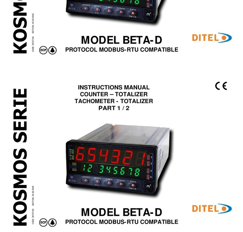
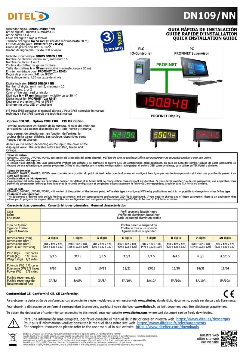
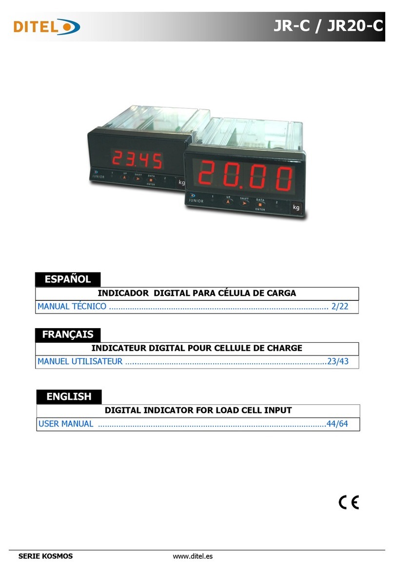
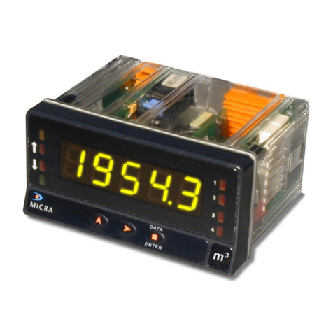
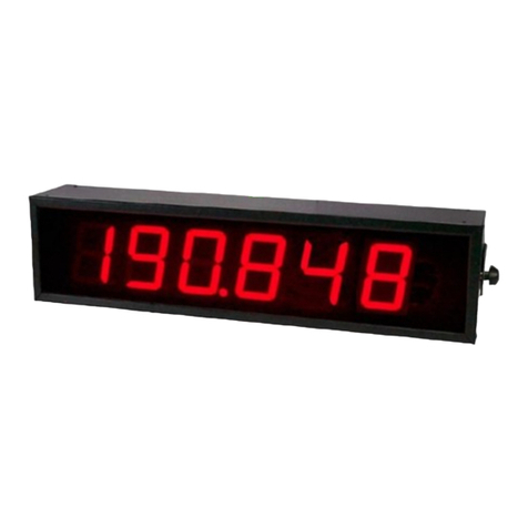
Ditel KOSMOS BETA-M User manual

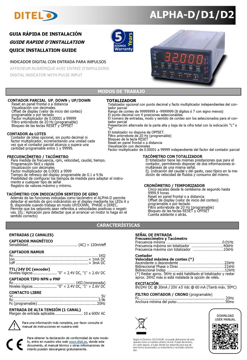
KOSMOS SERIE
CODE: 30727004 EDITION: 27-09-2010
KOSMOS SERIE
CODE: 30727004 EDITION: 27-09-2010
MODEL BETA-M
2 of 2
2 of 2
MODEL BETA-M

62
V
ersions Firmware 2.00
or later
Compatible Modbus
See page 86
Fail Safe Function
See page 108
Sensor Break Alarm
See page 107
36 Logical Functions
See page 67
Programming parameters lockout
See page 71
Back to Factory Configuration
See page 65
Linearization by segments
See page 36
3 Tare Modes
See page 105

DIGITAL PANEL INSTRUMENT BETA FAMILY
MODEL BETA-M
63
63
1 - Beta-M model overview ............................................................................................................................................6 - 7
1.1 Mode RUN: front-panel description........................................................................................................................8
1.2 Mode PROG: front-panel description......................................................................................................................9
2 - Getting started............................................................................................................................................................10
2.1 Power and connectors .................................................................................................................................11 - 12
2.2 Programming instructions ............................................................................................................................13 - 14
2.3 Programming guide............................................................................................................................................15
3 - Programming module 10. Input configuration diagram ...........................................................................................16 - 17
3.1 Program process input. Menu 11..................................................................................................................18 - 20
3.1.1 Connections (V, mA) ......................................................................................................................21 - 22
3.2 Program load cell input. Menu 12.................................................................................................................23 - 24
3.2.1 Connections (mV/ V).............................................................................................................................25
3.3 Program Pt100 input. Menu 13.....................................................................................................................26 - 27
3.3.1 Connections..........................................................................................................................................28
3.4 Program thermocouple input. Menu 14.........................................................................................................29 - 31
3.4.1 Connections (J, K, T, R, S, E).................................................................................................................32
3.5 Program potentiometer input. Menu 15 ...............................................................................................................33
3.5.1 Connections..........................................................................................................................................33
DIGITAL PANEL INSTRUMENT BETA FAMILY
MODEL BETA-M
Index
1 - Beta-M model overview............................................................................................................................................6 - 7
1.1 Mode RUN: front-panel description........................................................................................................................8
1.2 Mode PROG: front-panel description......................................................................................................................9
2 - Getting started............................................................................................................................................................10
2.1 Power and connectors.................................................................................................................................11 - 12
2.2 Programming instructions............................................................................................................................13 - 14
2.3 Programming guide............................................................................................................................................15
3 - Programming module 10. Input configuration diagram...........................................................................................16 - 17
3.1 Program process input. Menu 11..................................................................................................................18 - 20
3.1.1 Connections (V, mA) .....................................................................................................................21 - 22
3.2 Program load cell input. Menu 12.................................................................................................................23 - 24
3.2.1 Connections (mV/ V) ............................................................................................................................25
3.3 Program Pt100 input. Menu 13 ....................................................................................................................26 - 27
3.3.1 Connections.........................................................................................................................................28
3.4 Program thermocouple input. Menu 14.........................................................................................................29 - 31
3.4.1 Connections (J, K, T, R, S, E)................................................................................................................32
3.5 Program potentiometer input. Menu 15...............................................................................................................33
3.5.1 Connections.........................................................................................................................................33

DIGITAL PANEL INSTRUMENT BETA FAMILY
MODEL BETA-M
DIGITAL PANEL INSTRUMENT BETA FAMILY
MODEL BETA-M
64
64
4 - Programming module 20. Display configuration diagram ........................................................................................34 - 35
4.1 Scaling. Menus 21 and 22............................................................................................................................36 - 45
4.2 Integrator. Menu 23....................................................................................................................................46 - 48
4.3 Display options, Filters and Round ......................................................................................................................49
4.3.1 Display options. Menu 24 ..................................................................................................................... 50- 51
4.3.2 Filters. Menu 25..................................................................................................................................52 - 53
4.3.3 Round. Menu 26 ........................................................................................................................................54
4.4 Automatic volume calculation. Menu 27........................................................................................................55 - 58
5 - Front-panel functions and remote inputs
5.1 Front-panel functions ..............................................................................................................................59 and 65
5.2 Remote inputs ...................................................................................................................................................66
5.2.1 Table of remote input logic functions ...................................................................................................67 - 69
5.2.2 Program remote input logic functions..........................................................................................................70
6 - Programming parameters lockout.................................................................................................................................71
6.1 Lockout routine..................................................................................................................................................72
7 - Output options..................................................................................................................................................... 73 - 74
8 - Technical specifications ........................................................................................................................................75 - 76
8.1 Dimensions and mounting ..................................................................................................................................77
9 - Warranty....................................................................................................................................................................78
10 - Declaration of conformity ............................................................................................................................................80
A
NNEXES. Index................................................................................................................................................................82
4 - Programming module 20. Display configuration diagram ........................................................................................ 34 - 35
4.1 Scaling. Menus 21 and 22............................................................................................................................ 36 - 45
4.2 Integrator. Menu 23....................................................................................................................................46 - 48
4.3 Display options, Filters and Round ......................................................................................................................49
4.3.1 Display options. Menu 24 .................................................................................................................... 50 - 51
4.3.2 Filters. Menu 25.................................................................................................................................. 52 - 53
4.3.3 Round. Menu 26........................................................................................................................................54
4.4 Automatic volume calculation. Menu 27........................................................................................................ 55 - 58
5 - Front-panel functions and remote inputs
5.1 Front-panel functions ..............................................................................................................................59 and 65
5.2 Remote inputs ................................................................................................................................................... 66
5.2.1 Table of remote input logic functions ................................................................................................... 67 - 69
5.2.2 Program remote input logic functions..........................................................................................................70
6 - Programming parameters lockout.................................................................................................................................71
6.1 Lockout routine..................................................................................................................................................72
7 - Output options.....................................................................................................................................................73 - 74
8 - Technical specifications ........................................................................................................................................75 - 76
8.1 Dimensions and mounting ..................................................................................................................................77
9 - Warranty.................................................................................................................................................................... 78
10 - Declaration of conformity ............................................................................................................................................80
A
NNEXES. Index................................................................................................................................................................82
64

65
65
MAX/MIN key
Recalls the following parameters to the second display : first
push recalls peak, second push recalls valley, third push
recalls tare (or offset). If the integrator option is enabled, the
fourth push recalls total and, if not enabled but the logic
function nº30 (totalizer+batch) is programmed to one of the
user inputs a new push shows the number of batch
operations. The last push after this sequence blanks the
lower displays.
The auxiliary display indicates which variable is being read in
the second display : "HI" = peak, "Lo" = valley, "tA" = tare,
"oF" = offset, "bA" = nº of batches. The total value needs all
8 digits to be displayed.
A
ny selected parameter is permanently displayed and
continuously updated if no action is taken.
TO RESET PEAK, VALLEY, TOTAL or BATCH :
RESET key
Press MAX/MIN until desired parameter appears on the second
display. This parameter may be peak ('HI'), valley ('Lo'),
total (auxiliary digits blank or hi part of the total reading) or
number of batch operations ('bA').
When desired variable is being read on the lower displays,
hold the RESET key and press MAX/MIN . Release first MAX/MIN ,
then RESET .
A
tare or tare reset operation updates automatically the peak
and valley readings to the current display value.
ENTER key
A
momentary push of the ENTER key gives access to the
programming mode.
ENTER key (3s)
Gives access to the program lock-out routine. Hold ENTER
for approximately 3s, at the end of which the meter prompts
the indication '- - - -' to enter the security code.
RESET + ENTER (3s)
A
press of 3s of both RESET and ENTER restores the factory
settings to the memory of the instrument.
Press RESET first, then ENTER and hold both until the
indication "StorE" appears on the second display.
TARE RESET LIMIT MAX/MIN DATA
ESC ENTER
M
A
X
M
I
N
HOLD
TARE
1
2
3
4
TARE RESET LIMIT MAX/MIN DATA
ESC ENTER
M
A
X
M
I
N
HOLD
TARE
1
2
3
4

66
66
Factory Configuration
As shipped from the factory, the CN2 connector allows the
TARE, MAX/MIN and RESET operations be made in the same
way as from the front-panel keyboard and incorporates one
more function: the display HOLD.
If the user programs a '0' (no function) to all input pins, they
are automatically set to the default configuration.
CN2 : FACTORY DEFAULT CONFIGURATION
PIN (INPUT) Function Number
PIN 1 (INP-1) RESET Function nº 7
PIN 2 (INP-2) HOLD Function nº 9
PIN 3 COMMON
PIN 4 (INP-4) TARE Function nº 1
PIN 5 (INP-5) PEAK/VALLEY Function nº 6
The external electronics (fig.66.2) applied to the CN2
connector must be capable of withstanding 40 V and 20 mA
present at all terminals with respect to COMMON. In order to
guarantee the electromagnetic compatibility, please refer to
the instructions given on page 12.
5.2 - Logic Functions
The rear connector CN2 provides 4 user programmable opto-coupled inputs that can be operated from external contacts or
logic levels supplied by an electronic system. Four different functions may be added to the functions available from the front-
panel keys. Each function is associated to one of the CN2 connector pins (PIN 1, PIN 2, PIN 4 and PIN 5) and is activated by
applying a falling edge or a low level pulse to the corresponding pin with respect to common (PIN 3).
Each pin can be assigned one of the 36 functions listed on the following pages.
Fig.66.1
CN2 LOGIC
3 2 1 J1
•••
•••
6 5 4 J2
CN2 type of input
PNP J1 (2-3) J2 (5-6)
NPN J1 (1-2) J2 (4-5)
Fig.66.2. Examples
of PNP, NPN and
contact switch wiring.

67
9
67
5.2.1 - Table of programmable functions
Definition of the column "Action"
Edge : The function is active when a negative edge is applied to the corresponding pin referred to common.
Level : The function is active as long as the corresponding pin is held at a low level with respect to common.
(*) Factory configuration.
Nº Name Function Action
0 NO None -
1 TARE (*) Adds the current display value to the tare memory Edge
2 RESET TARE Clears the tare memory Edge
3 PEAK Recalls the peak value Level
4 VALLEY Recalls the valley value Level
5 RESET PEAK/VALLEY Resets peak and valley readings Edge
6 VISUAL (*) Recalls various parameters to the second display; Peak, Valley, Tare or Offset
and, if they are active, the Totalizer and the Batch counters. The last action
blanks the second display.
Edge
7 RESET (*) In combination with function (1) clears the tare memory.
In combination with function (6) clears the peak or valley memories, or the
totalizer or the batch counter
Edge
8 HOLD1 Holds the display Level
9 HOLD2 (*) Holds the display and the analog and BCD outputs Level
0 to 9 : DISPLAY AND MEMORY FUNCTIONS
10 to 12 : FUNCTIONS ASSOCIATED WITH THE MEASUREMENT DISPLA
Y
Nº Name Function Action
10 INPUT Displays the signal input value in V or mA, mV or mV from TC or ohms from Pt100 Level
11 GROSS Displays the gross value (measurement value + tare substracted) Level
12 TARE Displays the value of the tare memory Level

68
68
Nº Name Function Action
13 ANA GROSS The analog output follows the gross value (measured value + tare). Level
14 ANA ZERO Puts the analog output to the zero state (0V or 4mA) Level
15 ANA PEAK The analog output follows the peak value Level
16 ANA VALLEY The analog output follows the valley value Level
13 to 16 : FUNCTIONS ASSOCIATED TO THE ANALOG OUTPUT
17 to 23 : PRINT FUNCTIONS TO USE WITH RS232C or RS485 OUTPUTS
Nº Name Function Action
17 PRINT NET Prints the net value Edge
18 PRINT GROSS Prints the gross value Edge
19 PRINT TARE Prints the value of the tare Edge
20 PRINT SET1 Prints the value and the state of the setpoint 1 Edge
21 PRINT SET2 Prints the value and the state of the setpoint 2 Edge
22 PRINT SET3 Prints the value and the state of the setpoint 3 Edge
23 PRINT SET4 Prints the value and the state of the setpoint 4 Edge
24 to 25 : FUNCTIONS ASSOCIATED WITH THE SETPOINT OUTPUTS
Nº Name Function Action
24 FALSE SETPOINTS Allows programming and operation of four setpoints without setpoint card
installed Level
25 RESET SETPOINTS Unlocks the setpoint latched outputs Edge
26 to 36 : SPECIAL FUNCTIONS
Nº Name Function Action
26 ROUND RS Makes the serial output transmit the internal display value, without filters nor
rounding Level
27 ROUND BCD Makes the BCD output drive out the display value without rounding Level
Nº Name Function Action
13 ANA GROSS The analog output follows the gross value (measured value + tare). Level
14 ANA ZERO Puts the analog output to the zero state (0V or 4mA) Level
15 ANA PEAK The analog output follows the peak value Level
16 ANA VALLEY The analog output follows the valley value Level
13 to 16 : FUNCTIONS ASSOCIATED TO THE ANALOG OUTPUT
17 to 23 : PRINT FUNCTIONS TO USE WITH RS232C or RS485 OUTPUTS
Nº Name Function Action
17 PRINT NET Prints the net value Edge
18 PRINT GROSS Prints the gross value Edge
19 PRINT TARE Prints the value of the tare Edge
20 PRINT SET1 Prints the value and the state of the setpoint 1 Edge
21 PRINT SET2 Prints the value and the state of the setpoint 2 Edge
22 PRINT SET3 Prints the value and the state of the setpoint 3 Edge
23 PRINT SET4 Prints the value and the state of the setpoint 4 Edge
24 to 25 : FUNCTIONS ASSOCIATED WITH THE SETPOINT OUTPUTS
Nº Name Function Action
24 FALSE SETPOINTS Allows programming and operation of four setpoints without setpoint card
installed Level
25 RESET SETPOINTS Unlocks the setpoint latched outputs Edge
26 to 36 : SPECIAL FUNCTIONS
Nº Name Function Action
26 ROUND RS Makes the serial output transmit the internal display value, without filters nor
rounding Level
27 ROUND BCD Makes the BCD output drive out the display value without rounding Level

69
69
26 to 36 : SPECIAL FUNCTIONS (cont.)
Nº Name Function Action
28 ASCII Send the display last four digits to a Micra-S indicator Edge
29 SETS INHIBIT Suspends setpoint operations and keeps the outputs to their OFF state Level
30 BATCH Adds the current display value to the totalizer and increments the batch
counter in one unit.
If the integrator is enabled (menu 23), this function does not work
Edge
31 VIEW TOTAL Calls the totalizer value to the second display Level
32 VIEW BATCH Calls the batch counter to the second display Level
33 RESET
TOTAL+BATCH Resets the totalizer and the batch counter Edge
34 STOP TOTAL Inhibits the integrator operation Level
35 PRINT
TOTAL+BATCH Prints out the totalizer value and the batch counter value. If the integrator is
enabled, only the totalizer value is printed. Edge
36 PRINT PEAK Hold and print max reading.
When this function is programmed the peak value detection is stopped. In the
activation edge, the peak register is cleared from the memory and the unit
starts reading new peak values. In the deactivation edge, the peak value
registered during the time the function was active is printed out through the
serial output
Level

70
70
Menu 61 - Program Logic Input 1
Menu 61 Inp-1. Assign logic function to PIN 1.
The main display shows the function number assigned to logic input 1. Refer to the
table to select function and use the key to change the number if desired.
Pass to the programming of the following logic input.
ENTER Validate changes and return to the -Pro- stage.
ESC Exit from this menu and go to the -Pro- stage.
[70.2] Logic input PIN 1
5.2.2 - Program the logic functions
Press ENTER to enter in the programming mode (-Pro- level) and press repeatedly
until the indication shown in figure 70.1 appears on the display. From this
stage press ENTER to access the logic inputs configuration. The key rotates
around the four logic inputs to view the function number assigned to each pin.
The key changes the number if desired.
To program the logic inputs follow the procedure described below for input 1.
TARE RESET LIMIT MAX/MIN DATA
ESC ENTER
M
A
X
M
I
N
HOLD
TARE
1
2
3
4
Fig. 70.1: Logic inputs
configuration module
TARE RESET LIMIT MAX/MIN DATA
ESC ENTER
M
A
X
M
I
N
HOLD
TARE
1
2
3
4
Menu 61 - Program Logic Input 1
Menu 61 Inp-1. Assign logic function to PIN 1.
The main display shows the function number assigned to logic input 1. Refer to the
table to select function and use the key to change the number if desired.
Pass to the programming of the following logic input.
ENTER Validate changes and return to the -Pro- stage.
ESC Exit from this menu and go to the -Pro- stage.
[70.2] Logic input PIN 1
5.2.2 - Program the logic functions
Press ENTER to enter in the programming mode (-Pro- level) and press repeatedly
until the indication shown in figure 70.1 appears on the display. From this
stage press ENTER to access the logic inputs configuration. The key rotates
around the four logic inputs to view the function number assigned to each pin.
The key changes the number if desired.
To program the logic inputs follow the procedure described below for input 1.
TARE RESET LIMIT MAX/MIN DATA
ESC ENTER
M
A
X
M
I
N
HOLD
TARE
1
2
3
4
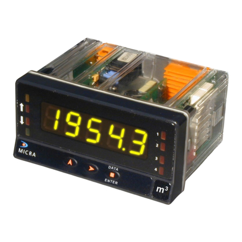
Fig. 70.1: Logic inputs
configuration module
TARE RESET LIMIT MAX/MIN DATA
ESC ENTER
M
A
X
M
I
N
HOLD
TARE
1
2
3
4

71
71
The instrument is supplied with all software programming
parameters accessible to operator's modifications. Afte
r
completing the software configuration, it is recommended to
take the following steps:
1. Lockout programming parameters to prevent from
accidental or unauthorized modifications.
2. Lockout the tare key operation.
3.
T
he lockout can be applied to everything or to specific
menus or parameters. If some parameters should be
reprogrammed frequently, make a partial lock leaving
such parameters accessible. If no subsequent adjus
t
must be made, make a total lock.
4.
T
he access to the lockout routine is allowed by entering
a safety code. At fabrication this code is set to 0000. We
recommend to change this code and to write it down and
keep safe.
5. Prior to configure the meter, it is recommended to
organize all data and keep a record s manual.
6. PARAMETER LOCKOUTS
TOTAL LOCKOUT
T
he access to the programming routines to read data is
allowed even if all parameters are locked out, but it won’t
be possible to enter or modify data. In this case, when
entering in the programming mode, the second display shows
the indication -dAtA- instead of -Pro-.
SELECTIVE LOCKOUT
When only some parameters are locked out, all configuration
data can be read but only non-protected parameters can
be modified. In such case, when entering in the
programming mode, the second display shows the indication
-Pro-.
Selective lock-outs include the following groups:
•Setpoint 1 configuration (menu 31).
•Setpoint 2 configuration (menu 32).
•Setpoint 3 configuration (menu 33).
•Setpoint 4 configuration (menu 34).
•Input configuration (module 10).
•Scaling (menus 21/22, 23 and 27).
•Display options and filtering (menus 24, 25 and 26).
•Analog output configuration (module 40).
•Serial output configuration (module 50).
•Logic inputs configuration (module 60).
•Direct access to the programming of the setpoint values
Those that refer to optional outputs only appear if the
corresponding option is installed.
T
he instrument is supplied with all software programming
parameters accessible to operator's modifications. Afte
r
completing the software configuration, it is recommended to
take the following steps:
1. Lockout programming parameters to prevent from
accidental or unauthorized modifications.
2. Lockout the tare key operation.
3.
T
he lockout can be applied to everything or to specific
menus or parameters. If some parameters should be
reprogrammed frequently, make a partial lock leaving
such parameters accessible. If no subsequent adjus
t
must be made, make a total lock.
4.
T
he access to the lockout routine is allowed by entering
a safety code. At fabrication this code is set to 0000. We
recommend to change this code and to write it down and
keep safe.
5. Prior to configure the meter, it is recommended to
organize all data and keep a record s manual.
6. PARAMETER LOCKOUTS
TOTAL LOCKOUT
T
he access to the programming routines to read data is
allowed even if all parameters are locked out, but it won’t
be possible to enter or modify data. In this case, when
entering in the programming mode, the second display shows
the indication -dAtA- instead of -Pro-.
SELECTIVE LOCKOUT
When only some parameters are locked out, all configuration
data can be read but only non-protected parameters can
be modified. In such case, when entering in the
programming mode, the second display shows the indication
-Pro-.
Selective lock-outs include the following groups:
•Setpoint 1 configuration (menu 31).
•Setpoint 2 configuration (menu 32).
•Setpoint 3 configuration (menu 33).
•Setpoint 4 configuration (menu 34).
•Input configuration (module 10).
•Scaling (menus 21/22, 23 and 27).
•Display options and filtering (menus 24, 25 and 26).
•Analog output configuration (module 40).
•Serial output configuration (module 50).
•Logic inputs configuration (module 60).
•Direct access to the programming of the setpoint values
Those that refer to optional outputs only appear if the
corresponding option is installed.

72
72
6.1 - Lockout programming routine
The lock-out programming routine is entered by depressing
the ENTER key for 3 seconds and introducing a security code.
T
his gives access to either the parameter list or to change the
code if desired.
If the user opts for changing the code, the unit asks for the
new one and returns to the normal operation. The old code is
replaced with the user selected one, that will be asked next
time this routine is entered.
When the user enters the parameter list, each parameter is
indicated in the second display, while in the first one a
blinking digit allows setting a ‘1’ to lock this item, or a ‘0’ to
free it.
There are two ways to lock-out the program; One is to lock
everything, which is accomplished by setting a ‘1’ in the ‘tot-
LC’ parameter (the remaining parameters are skipped except
the tare key lock).
The second is to individually lock some parts of the program
menus leaving free those parts which are more liable to have
changes during normal operation.
88888
3s?
----
CodE
-YES-
CHAnG
-no-
CHAnGE
0
tot-LC
tot-LC?
0
tArE
0
SEt1
0
SEt2
0
SEt3
0
SEt4
0
InPu
t
0
SCAL
0
FILt
0
A
nAou
t
0
rs coM
0
LoGInP
0
SP VAL
----
CodE
code O
K
1
0
yes
no
yes

73
73
Output options with instructions manual edited before
December 1999, work properly with new versions o
f
Beta-M but some new features may not be described in
the options manual.
If you are using an older output card connected to a
new Beta-M and you want to take benefit of the ne
w
functions (see page 60), please call for an updated
edition of the options manual.
Optionally, model BETA-M can incorporate one or several
output options for communications or control including :
COMMUNICATION
RS2 Serial RS232C
RS4 Serial RS485
BCD BCD 24V/TTL
CONTROL
ANA Analogue 4-20 mA, 0-10 V
2RE 2 SPDT relays 8 A
4RE 4 SPST relays 5 A
4OP 4 open-collector NPN outputs
4OPP 4 open-collector PNP outputs
A
ll options are optoisolated with respect to the input signal.
T
he options are supplied with a specific instructions manual
describing characteristics, installation, connections and
programming. The output cards are easily installed on the
meter's main board by means of plug-in connectors and each
one activates its own programming module that provides
complete software-configuration.
A
dditional capabilities of the unit with output options :
•Control and processing of limit values via ON/OFF logic
outputs (2 relays, 4 relays, 4 NPN outputs or 4 PNP
outputs) or proportional output (4-20 mA or 0-10 V).
•Communication, data transmission and remote
programming via serial interface.
For more detailed information on characteristics, applications,
mounting and programming, please refer to the specific
manual supplied with each option.
7. OUTPUT OPTIONS

74
74
The figure shows the main circuit board locations of the
available output options. Each plug-in location can
accept only one card from a particular function type.
The options 2RE, 4RE, 4OP and 4OPP are for setpoint
control and only one of them can be installed in the M5
location.
The options RS2 and RS4 are for communication and
only one of them can be installed in the M1 location.
The ANA option provides selectable 0-10V and 20mA
analog output and is installed in the M4 location.
Up to three output options can be present at a time and
operate simultaneously:
- ANALOGUE, 0-10V or 4-20mA
- RS232C or RS485 (one of them),
- 2 RELAYS, 4 RELAYS or 4 NPN or 4 PNP outputs
(one of them).
T
he BCD output is exclusive and it does not allow any of
the others. This option is attached to the main circuit
board by means of a 18-pin FLAT cable.

75
75
Temperature input
•Cold junction compensation...................-10 ºC to +60 ºC
•Cold junction ..............................±(0.05 ºC/ ºC +0.1 ºC)
•Pt100 excitation current ................................ < 1 mA DC
•Max. cable resistance...................40 Ω/ cable (balanced)
•Temperature coefficient ..............................100 ppm/ ºC
Input Ran
g
e (0.1 º) Accuracy (0.1º) Ran
g
e (1º) Accuracy (1º)
TC J
-200.0 to
+1100.0 ºC 0.4% L ±0.6 ºC -200 to
+1100 ºC 0.4% L ±1 º C
-328.0 to
+2012.0 ºF 0.4% L ±1 ºF -328 to
+1472 ºF 0.4% L ±2 º F
TC K
-200.0 to
+1200.0 ºC 0.4% L ±0.6 ºC -200 to
+1200 ºC 0.4% L ±1 º C
-328.0 to
+2192.0 ºF 0.4% L ±1 ºF -328 to
+2192 ºF 0.4% L ±2 º F
TC T
-150.0 to
+400.0 ºC 0.4% L ±0.6 ºC -150 to
+400 ºC 0.4% L ±1 º C
-302.0 to
+752.0 ºF 0.4% L ±1 ºF -302 to
+752 ºF 0.4% L ±2 º F
TC R
-50.0 to
1700.0 ºC 0.5% L ±2 ºC -50 to
1700 ºC 0.5% L ±4 º C
-58.0 to
+3092.0 ºF 0.5% L ±4 ºF -58 to
+3092 ºF 0.5% L ±7 º F
TC S
-50,0 to
1700,0 ºC 0.5% L ±2 ºC -50 to
1700 ºC 0.5% L ±4 º C
-58.0 to
+3092.0 ºF 0.5% L ±4 ºF -58 to
+3092 ºF 0.5% L ±7 º F
TC E
-200.0 to
1000.0 ºC 0.4% L ±1 ºC -200 to
1000 ºC 0.4% L ±2 ºC
-328.0 to
+1832.0 ºF 0.4% L ±2 ºF -328 to
+1832 ºF 0.4% L ±4 ºF
Pt100
-100.0 to
+800.0 ºC 0.2% L ±0.6 ºC -100 to
+800 ºC 0.2% L ±1 ºC
-148.0 to
+1472.0 ºF 0.2% L ±1 ºF -148 to
+1472 ºF 0.2% L ±2 ºF
8. TECHNICAL SPECIFICATIONS
INPUT SIGNAL
•Configuration ......................... differential asymmetrical
Process input Voltage Current
•Voltage...............................±10V DC......... ±20mA DC
•Max. resolution........................0.1mV....................1µA
•Input impedance ....................... 1MΩ................... 15Ω
•Excitation........................24V (30mA), 10/ 5V (120mA)
•Max error..................± (0.1% of the reading +3 digits)
•Temperature coefficient........................... 100 ppm/ ºC
Load cell input
•Voltage................................................... ±300 mV DC
•Max. resolution................................................0.15 µV
•Input impedance .............................................100 MΩ
•Excitation...........................................10/ 5V (120 mA)
•Max error..................± (0.1% of the reading +6 digits)
•Temperature coefficient........................... 100 ppm/ ºC
Potentiometer input
•Voltage.........................................................±10V DC
•Input impedance ................................................. 1MΩ
•Display resolution............................................0.001%
•Max error..................± (0.1% of the reading +3 digits)
•Temperature coefficient........................... 100 ppm/ ºC
Temperature input
•Cold junction compensation...................-10 ºC to +60 ºC
•Cold junction ..............................±(0.05 ºC/ ºC +0.1 ºC)
•Pt100 excitation current ................................ < 1 mA DC
•Max. cable resistance...................40 Ω/ cable (balanced)
•Temperature coefficient ..............................100 ppm/ ºC
Input Ran
g
e (0.1 º) Accuracy (0.1º) Ran
g
e (1º) Accuracy (1º)
TC J
-200.0 to
+1100.0 ºC 0.4% L ±0.6 ºC -200 to
+1100 ºC 0.4% L ±1 º C
-328.0 to
+2012.0 ºF 0.4% L ±1 ºF -328 to
+1472 ºF 0.4% L ±2 º F
TC K
-200.0 to
+1200.0 ºC 0.4% L ±0.6 ºC -200 to
+1200 ºC 0.4% L ±1 º C
-328.0 to
+2192.0 ºF 0.4% L ±1 ºF -328 to
+2192 ºF 0.4% L ±2 º F
TC T
-150.0 to
+400.0 ºC 0.4% L ±0.6 ºC -150 to
+400 ºC 0.4% L ±1 º C
-302.0 to
+752.0 ºF 0.4% L ±1 ºF -302 to
+752 ºF 0.4% L ±2 º F
TC R
-50.0 to
1700.0 ºC 0.5% L ±2 ºC -50 to
1700 ºC 0.5% L ±4 º C
-58.0 to
+3092.0 ºF 0.5% L ±4 ºF -58 to
+3092 ºF 0.5% L ±7 º F
TC S
-50,0 to
1700,0 ºC 0.5% L ±2 ºC -50 to
1700 ºC 0.5% L ±4 º C
-58.0 to
+3092.0 ºF 0.5% L ±4 ºF -58 to
+3092 ºF 0.5% L ±7 º F
TC E
-200.0 to
1000.0 ºC 0.4% L ±1 ºC -200 to
1000 ºC 0.4% L ±2 ºC
-328.0 to
+1832.0 ºF 0.4% L ±2 ºF -328 to
+1832 ºF 0.4% L ±4 ºF
Pt100
-100.0 to
+800.0 ºC 0.2% L ±0.6 ºC -100 to
+800 ºC 0.2% L ±1 ºC
-148.0 to
+1472.0 ºF 0.2% L ±1 ºF -148 to
+1472 ºF 0.2% L ±2 ºF
8. TECHNICAL SPECIFICATIONS
INPUT SIGNAL
•Configuration ......................... differential asymmetrical
Process input Voltage Current
•Voltage...............................±10V DC......... ±20mA DC
•Max. resolution........................0.1mV....................1µA
•Input impedance ....................... 1MΩ................... 15Ω
•Excitation........................24V (30mA), 10/ 5V (120mA)
•Max error..................± (0.1% of the reading +3 digits)
•Temperature coefficient............................100 ppm/ ºC
Load cell input
•Voltage................................................... ±300 mV DC
•Max. resolution................................................0.15 µV
•Input impedance .............................................100 MΩ
•Excitation...........................................10/ 5V (120 mA)
•Max error..................± (0.1% of the reading +6 digits)
•Temperature coefficient............................100 ppm/ ºC
Potentiometer input
•Voltage.........................................................±10V DC
•Input impedance ..................................................1MΩ
•Display resolution............................................0.001%
•Max error..................± (0.1% of the reading +3 digits)
•Temperature coefficient............................100 ppm/ ºC

76
76
ENVIRONMENTAL
(indoor use)
•Operating temperature.......................-10 ºC to +60 ºC
•Storage temperature..........................-25 ºC to +85 ºC
•Relative humidity.................................<95 % at 40 ºC
•Max. altitude ............................................2000 meters
MECHANICAL
•Dimensions ..........................................96x48x120 mm
•Panel cutout................................................92x45 mm
•Weight...............................................................600 g
•Case material ................UL 94 V-0 rated polycarbonate
ELECTRICAL SAFETY
•Installation category.................................................II
•Degree of pollution....................................................2
FUSES (DIN 41661) - Not supplied
•Beta-M (230/115V AC)..........................F 0.2 A / 250 V
•Beta-M2 (24/48V AC)............................F 0.5 A / 250 V
A
/D CONVERSION
•Technique.................................................Sigma-Delta
•Resolution........................................................(24 bit)
•Rate ....................................................................18/s
A
CCURACY at 23º ± 5º C
•Temperature coefficient............................100 ppm/ ºC
•Warm-up time.................................................. 10 min
POWER SUPPLY
•AC voltages....230/115 V, 24/48 V (±10%) 50/60 Hz AC
•Consumption.............5W (without options), 10W (max)
DISPLAY
•Main..............-99999/ +99999, 6 digits red LED 14 mm
•Secondary..............................6 digits green LED 8 mm
•Auxiliary.................................2 digits green LED 8 mm
•Decimal point........................................programmable
•LEDs............................ 4 functions and 4 output status
•Reading rate ...............................55.5 ms/ 250 ms/ 1 s
•Positive overrange..............................................oVFLo
•Negative overrange .......................................... -oVFLo
•Sensor Break.....................................................“------“
ENVIRONMENTAL
(indoor use)
•Operating temperature.......................-10 ºC to +60 ºC
•Storage temperature..........................-25 ºC to +85 ºC
•Relative humidity.................................<95 % at 40 ºC
•Max. altitude ............................................2000 meters
MECHANICAL
•Dimensions ..........................................96x48x120 mm
•Panel cutout................................................92x45 mm
•Weight...............................................................600 g
•Case material ................ UL 94 V-0 rated polycarbonate
ELECTRICAL SAFETY
•Installation category.................................................II
•Degree of pollution....................................................2
FUSES (DIN 41661) - Not supplied
•Beta-M (230/115V AC)..........................F 0.2 A / 250 V
•Beta-M2 (24/48V AC)............................F 0.5 A / 250 V
A
/D CONVERSION
•Technique.................................................Sigma-Delta
•Resolution........................................................(24 bit)
•Rate ....................................................................18/s
A
CCURACY at 23º ± 5º C
•Temperature coefficient............................100 ppm/ ºC
•Warm-up time.................................................. 10 min
POWER SUPPLY
•AC voltages....230/115 V, 24/48 V (±10%) 50/60 Hz AC
•Consumption.............5W (without options), 10W (max)
DISPLAY
•Main..............-99999/ +99999, 6 digits red LED 14 mm
•Secondary..............................6 digits green LED 8 mm
•Auxiliary.................................2 digits green LED 8 mm
•Decimal point........................................programmable
•LEDs............................ 4 functions and 4 output status
•Reading rate ...............................55.5 ms/ 250 ms/ 1 s
•Positive overrange..............................................oVFLo
•Negative overrange .......................................... -oVFLo
•Sensor Break.....................................................“------“

77
77
8.1 - Dimensions and mounting
To mount the instrument into the panel, make a cutout of
92x45mm. Slide the sealing gasket over the instrument's
case to the bezel and insert the instrument through the
panel cutout from the front.
PANEL CUTOUT
92 mm
45 mm
Place the fixing clips on both sides of the case and push
them over the rear until they touch the panel.
A
pply pressure to engage the tabs on the fixing clips to
the slots of the case.
To remove the instrument from the panel, pull outwards
the fixing clips from the rear tabs to disengage and slide
them back over the case.
CLEANING: The font cover should be cleaned
only with a soft cloth soaked in neutral soap
products. DO NOT USE SOLVENTS
SEALING GASKET
PANEL
FIXING CLIPS

78
78
The instruments are warranted against defective materials and workmanship for a period of
three years from date of delivery.
If a product appears to have a defect or fails during the normal use within the warranty
period, please contact the distributor from which you purchased the product.
This warranty does not apply to defects resulting from action of the buyer such as
mishandling or improper interfacing.
The liability under this warranty shall extend only to the repair of the instrument. No
responsibility is assumed by the manufacturer for any damage which may result from its
use.
All the DITEL products benefit from an unlimited and unconditional warranty of THREE (3)
years from the date of their purchase. Now you can extend this period of warranty up to
FIVE (5) years from the product commissioning, only by fulfilling the corresponding form.
Fill up the form in our website at:
http://www.ditel.es/warranty

79
79

10. DECLARATION OF CONFORMIT
Y
Manufacturer :
DITEL - Diseños y Tecnología S.A.
Address :
Polígono Industrial Les Guixeres
C/ Xarol 8 C
08915 BADALONA-SPAIN
Declares, that the product :
Description : Digital panel multifunction meter
Model : BETA-M
Conforms with the directives : EMC 2004/108/CEE
LVD 2006/95/CEE
Applicable Standars :
EN50081-1 Generic emission
EN55022/CISPR22 Class B
Applicable Standars :
EN50082-1 Generic immunity
IEC1000-4-2 Level 3 Criteria B
Air Discharge 8kV
Contact Discharge 6kV
IEC1000-4-3 Level 2 Criteria A
3V/m 80..1000MHz
IEC1000-4-4 Level 2 Criteria B
1kV Power Lines
0.5kV Signal Lines
Applicable Standars :
EN61010-1 Generic Safety
IEC1010-1 Installation Category II
Transient Voltages <2.5kV
Pollution Degree 2
Conductive pollution excluded
Insulation Type
Enclosure : Double
Inputs/Outputs : Basic
Date: 20 July 2010
Signed: José M. Edo
Position: Technical Manager
80
80
Table of contents
Other Ditel Measuring Instrument manuals

Ditel
Ditel Kosmos series User manual

Ditel
Ditel JUNIOR JR-D User manual

Ditel
Ditel KOSMOS MICRA-D User manual

Ditel
Ditel KOSMOS MICRA-X User manual

Ditel
Ditel DINOS DT Series User manual

Ditel
Ditel MICRA-D User manual

Ditel
Ditel MICRA-NE6 User manual

Ditel
Ditel BETA-D User manual

Ditel
Ditel JUNIOR JR-C User manual

Ditel
Ditel KOSMOS PICA-T User manual

Ditel
Ditel MICRA-M User manual

Ditel
Ditel Kosmos series User manual

Ditel
Ditel MICRA-NE User manual

Ditel
Ditel JUNIOR JR20-P User manual

Ditel
Ditel ALPHA-D User manual

Ditel
Ditel DN119/NN User manual

Ditel
Ditel DINOS DT110/NE User manual

Ditel
Ditel DINOS DN189/P User manual

Ditel
Ditel JUNIOR JR-E User manual

Ditel
Ditel DINOS DN Series User manual