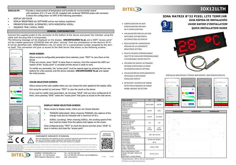
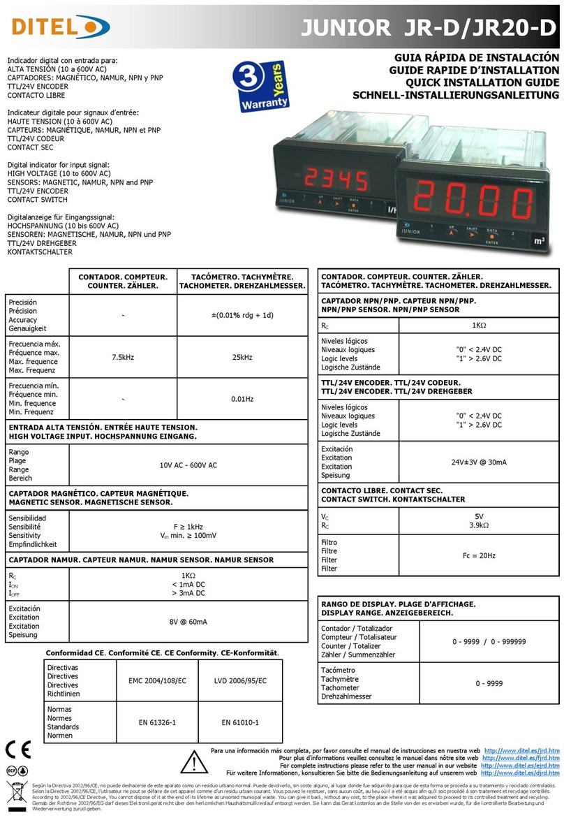
Orificio en panel
Orifice dans le pannea
Panel cutout
Schalttafel-Ausschnitt
92 x 45 mm
Estanqueidad frontal
Étanchéité du frontal
Frontal protection degree
Frontplatte Schutzart
IP65
Dimensiones y montaje
Dimensions et montage
Dimensions and mounting
Abmessungen und Montage
CN2 CN3
CN1
CN7 CN5 CN4
CN6
CN2 INPUT SIGNAL PROCES
PIN 1 = -EXC [excitation output (-)]
PIN 2 = +EXC [excitation output +24V (+)]
PIN 3 = +EXC [excitation output +5V or 10V (+)]
PIN 4 = N/C [no connection]
PIN 5 = +IN [input mA (+)]
PIN 6 = +IN [input V (+)]
PIN 7 = N/C [no connection]
PIN 8 = -IN [input V (-), mA(-)]
WIRING and POWER SUPPLY RANGE
MICRA-M
85 V – 265 V AC 50/ 60 Hz to 100 – 300 V DC
MICRA-M6
22 – 53 V AC 50/ 60 Hz to 10,5 - 70 V DC
PIN 1: Phase / VDC PIN 2: Neutral / VDC
Recommended fuse : MICRA-M (0.5A)
MICRA-M6 (2A)
NOTE: When DC power supply polarity
in connector CN1 is indistinct.
1 2 1 8 1 4
CN2 INPUT SIGNAL STRAIN GAUGE
PIN 1 = -EXC [excitation output (-)]
PIN 2 = N/C [no connection]
PIN 3 = +EXC [excitation output +5V or 10V (+)]
PIN 4 = N/C [no connection]
PIN 5 = N/C [no connection]
PIN 6 = N/C [no connecon]
PIN 7 = +IN [input mV (+)]
PIN 8 = -IN [input mV (-)]
CN2 INPUT SIGNAL TEMPERATURE
PIN 1 = N/C [no connection
PIN 2 N/C [no connection]
PIN 3 = N/C [no connection]
PIN 4 = Pt100 Common
PIN 5 = N/C [no connection]
PIN 6 = N/C [no connection]
PIN 7 = Pt100 / +TC
PIN 8 = Pt100 / -TC
PIN (INPUT) Function Number
PIN 1 COMMON
PIN 2 (INP-1) TARE Function nº 1
PIN 3 (INP-2) RESET TARE Function nº 2
PIN 4 (INP-3) HOLD Function nº 6
CN3 DIGITAL INPUTS (Factory Configuration)
41
52
63
1
2
CN4 ANALOG OUTPUT SIGNAL
4-20mA (OPTION)
PIN 1 = (-) [4-20 mA]
PIN 2 (+) [4-20 mA]
0-10V (OPTION)
PIN 1 = (-) [0-10V]
PIN 2 = (+) [0-10V]
CN6 / CN7 RELAIS OUTPUT
2RE OPTION 4RE OPTION 4OP/4OPP OPTION
PIN 1 = NO1
PIN 2= COMM1
PIN 3 = NC1
PIN 4 = NO2
PIN 5 = COMM2
PIN 6 = NC2
PIN 1 = RL1
PIN 2= RL2
PIN 3 = RL3
PIN 4 = RL4
PIN 5 = N/C
PIN 6 = COMMON
PIN 1 = OPTO1
PIN 2 = OPTO2
PIN 3 = OPTO3
PIN 4 = OPTO4
PIN 5 = N/C
PIN 6 = COMMON
Fusible Relé recomendado :
Fusible Relais recommandé :
Recommended Relais fuse :
Empfohlene Sicherungrelais :
** IMPORTANTE! / IMPORTANT! / WICHTIG!
Para garantizar la seguridad eléctrica de acuerdo con EN
61010-1 deberá instalarse como medida de protección un
fusible externo.
Pour garantir le sécurité électrique selon EN 61010-1 il faut
installer un fusible externe de protection.
To guarantee electrical safety according to EN 61010-1 a
protective external fuse must be installed.
Um die elektrische Sicherheit nach EN 61010-1 zu
garantieren, muss eine externe Sicherung installiert werden.
20230210
DISEÑOS Y TECNOLOGÍA, S.A.
Xarol, 6B P.I. Les Guixeres
08915 Badalona (Barcelona) - Spain
Tel. +34 933 394 758
Fax +34 934 903 145
Nota: Para obtener información adicional sobre el cableado,
descargue el manual completo de nuestro sio web
Remarque: Pour plus d'informaons sur le câblage, téléchar-
gez le manuel complet sur notre site Web
Note: For addional wiring informaon download complete
manual from our website
Hinweis: Für zusätzliche Informaonen zur Verkabelung laden
Sie das vollständige Handbuch von unserer Website herunter
