Feature
ScootTMis d sign d for small indoor
applications and allows you to
prot ct almost any ar a of your
hous . Applications includ
prot cting your furnitur , drap s,
carp ts, window sills, count rtops,
stairways, b ds, cribs, tc.
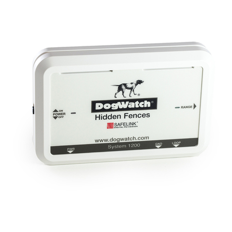
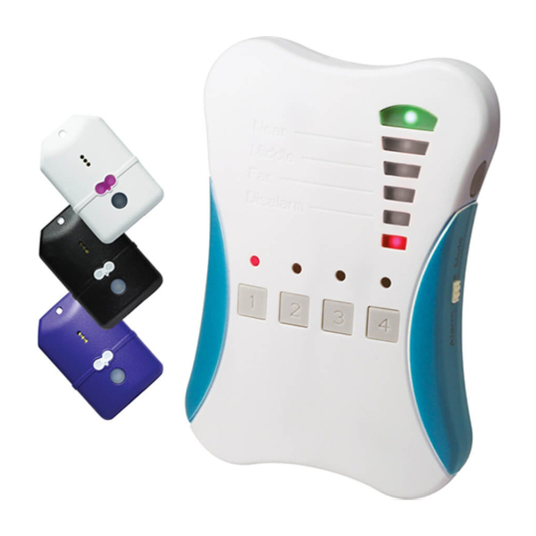
Power Simply plug th pow r
supply into th transmitt r jack.
I dicator Light A gr n light l ts
you know that both th transmitt r
and boundary wir ar functioning
prop rly. A r d light l ts you know
that your boundary wir is not
conn ct d prop rly or has a br ak.
Ra ge Th transmitt r mits a
cod d radio signal through up to 25 f t of boundary wir . You can
adjust th distanc th signal radiat s off th boundary wir by
using th l ft switch on th back of Scoot. Wh n th switch is s t to
th “HIGH” position, th rang will b approximat ly two f t off th
wir . Wh n th switch is s t to th “LOW” position, th rang will b
approximat ly on foot off th wir . Always t st th signal fi ld
b for allowing your p t n ar th avoidanc ar a. N v r adjust th
transmitt r whil your p t is w aring th r c iv r collar.
Termi al Co ectio s Strip and conn ct on nd of th boundary
wir to on of th t rminal conn ctions. This is th b ginning of
your boundary wir syst m. Onc you hav compl t d your
boundary, strip and conn ct th oth r nd of your boundary wir to
th oth r t rminal. Th boundary wir must mak a compl t loop.
If th gr n pow r light turns to r d it m ans that your boundary
wir is not conn ct d prop rly or that th r is a br ak in th wir .
Adju ting the Collar
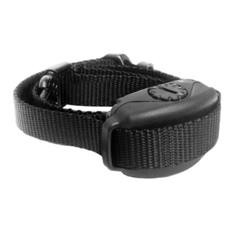
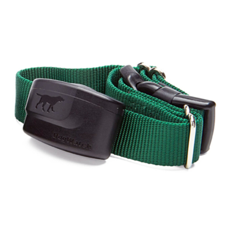
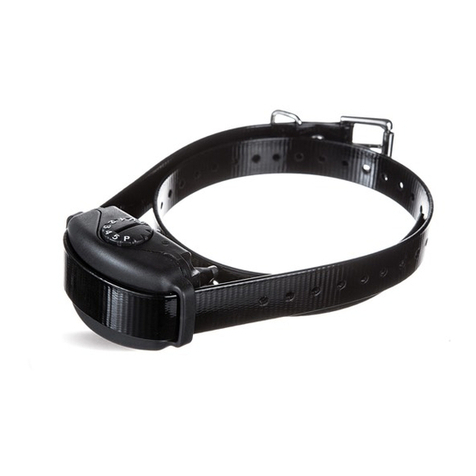
Collar tightn ss is critical. All contact points must touch your dog’s
skin in ord r to r c iv a corr ction. A loos collar will also allow th
contact posts to rub back and forth on th skin, possibly causing
irritation. Us car as ov r-tight ning th contact posts could caus
damag to th r c iv r.
W r comm nd that th r c iv r collar b r mov d ach day to
allow your dog’s skin to gradually condition its lf to th contact
posts and avoid pot ntial skin irritation and possibl inf ctions.
In tallation
To cr at a signal fi ld using th boundary wir , you n d to
s parat th two strips of wir . Th rang of th signal will d p nd
upon th distanc th two strips of wir ar from on anoth r. Wh n
th two strips ar n xt to on anoth r, th r is no signal fi ld. As th
two strips ar s parat d, th signal fi ld will incr as (see Figure 1).
Th boundary wir must form a continuous loop for th r to b a
signal fi ld. To accomplish this, you must splic th final nds of th
boundary wir tog th r.
Th boundary wir carri s a harml ss radio signal. You do not n d
to worry about an l ctrical shock wh n s parating and splicing th
boundary wir . Th pow r indicator light will b “r d” if you hav not
clos d th boundary loop or if you hav a brok n boundary wir .
32
Note: On th back of Scoot th r ar two small switch s. Th right
switch s ts your transmitt r to th corr ct broadcast fr qu ncy.
Your d al r will s t this right switch for your syst m.
Do NOT cha ge these setti gs. They are for DEALER USE ONLY.
Smaller Sig al Field
Larger Sig al Field
Splice The E ds Together
Figure 1


