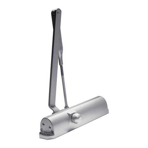
Dormakaba SVI 2 Series Training manual
Other Dormakaba Door Opening System manuals
Dormakaba
Dormakaba ED100 User manual
Dormakaba
Dormakaba TSG-H User manual

Dormakaba
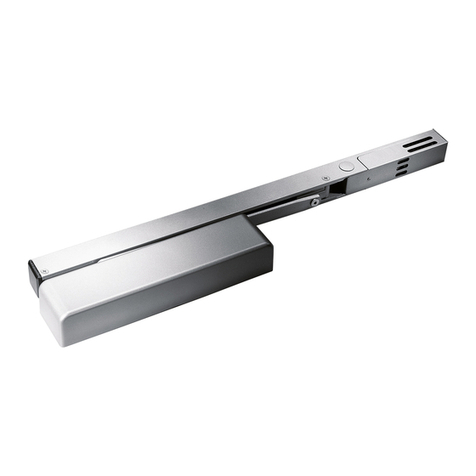
Dormakaba TS 98 XEA User manual
Dormakaba
Dormakaba G-SR EMR Series Manual
Dormakaba
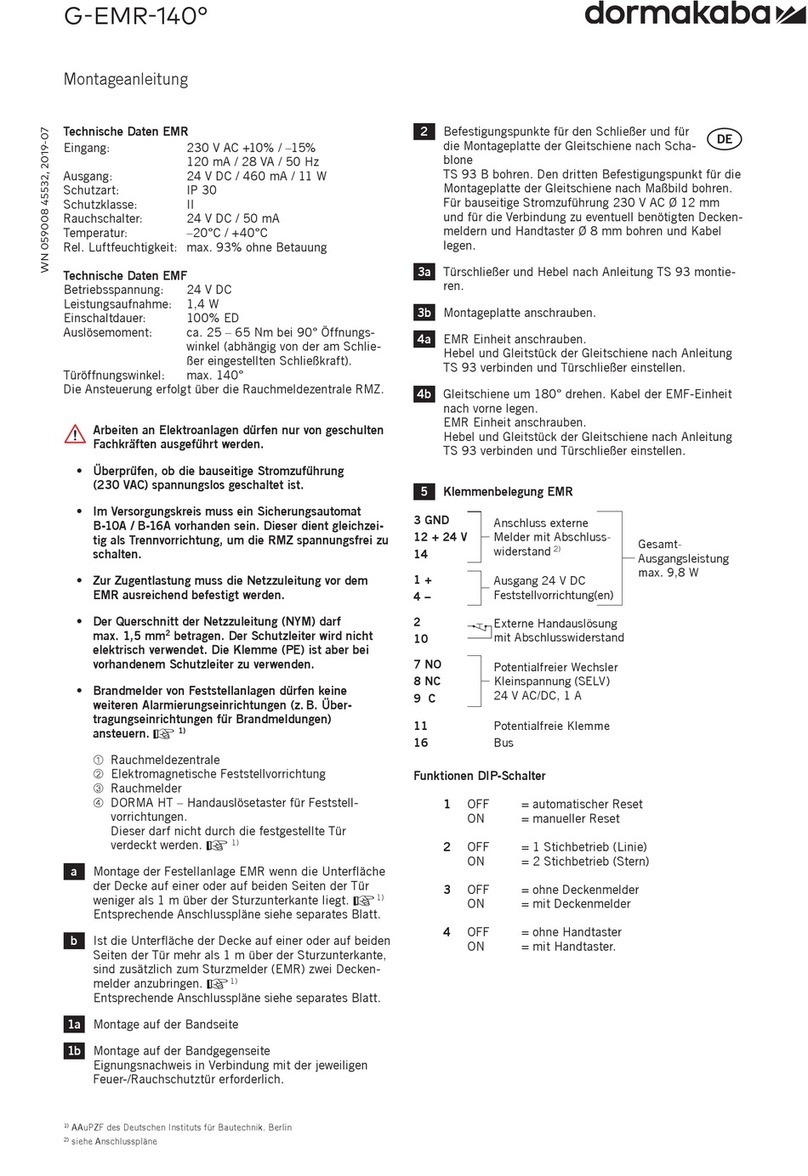
Dormakaba G-EMR-140 Manual

Dormakaba
Dormakaba ED50LE User manual
Dormakaba
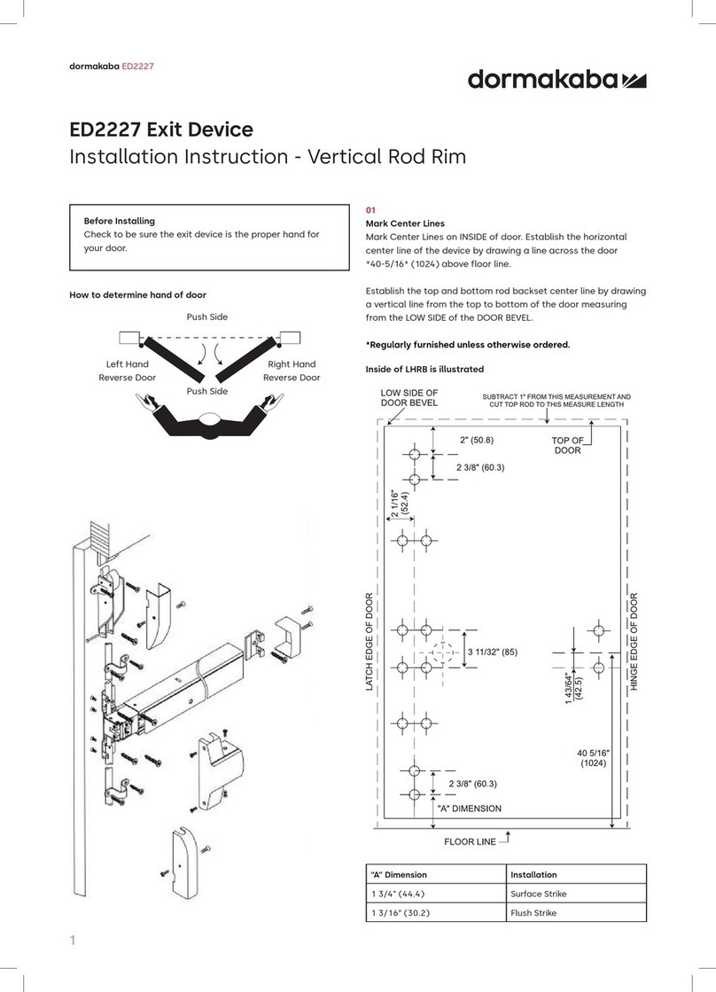
Dormakaba ED2227 User manual
Dormakaba
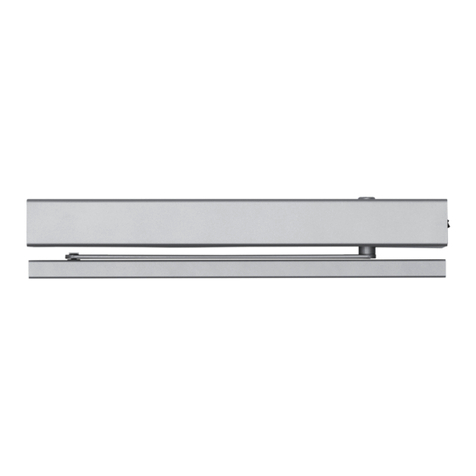
Dormakaba 8600T EMR User manual
Dormakaba
Dormakaba ED900 Guide

Dormakaba
Dormakaba ED900 User manual

Dormakaba
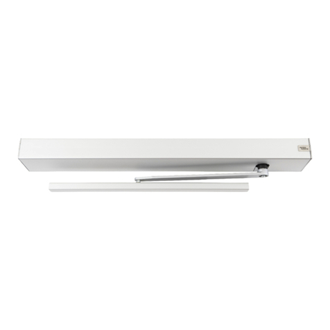
Dormakaba 8900 TDE User manual
Dormakaba
Dormakaba ED50LE User manual

Dormakaba
Dormakaba CS 80 MAGNEO User manual
Dormakaba
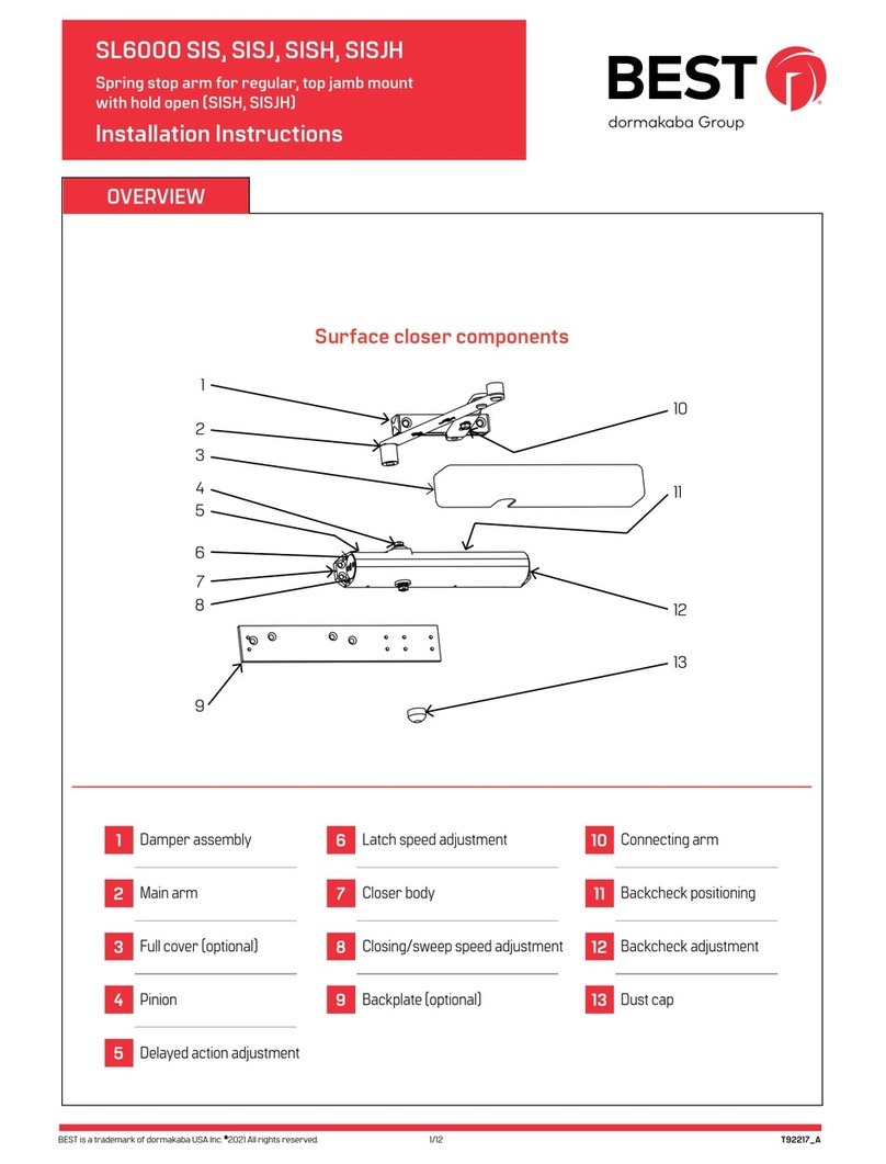
Dormakaba Best SL6000 SIS User manual

Dormakaba
Dormakaba ORACODE 480 Series User manual

Dormakaba
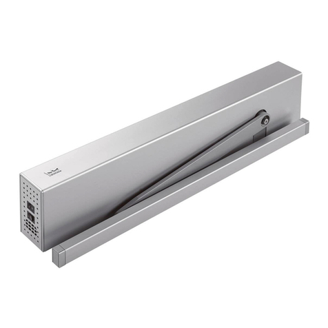
Dormakaba ED100 Installation and operation manual
Dormakaba
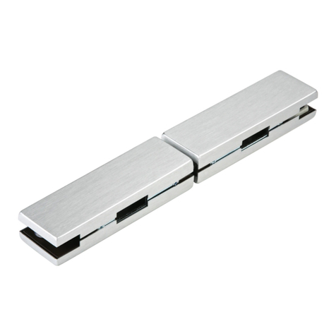
Dormakaba ED50 User manual
Dormakaba
Dormakaba UNIVERSAL GK 20 User manual

Dormakaba
Dormakaba TS93 Series User manual
Dormakaba
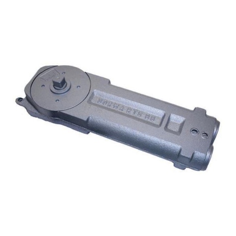
Dormakaba RTS88 User manual
Popular Door Opening System manuals by other brands

Besam
Besam Swingmaster MP Installation, adjustment and maintenance instructions

Assa Abloy
Assa Abloy SARGENT 1431 Series instructions

GAL
GAL MOVFR Quick setup

Häfele
Häfele Finetta T 70 VF manual

AGS
AGS D-PL Instructions for fitting, operating and maintenance

Stanley
Stanley MA900ñ Installation and owner's manual

WITTUR
WITTUR Hydra Plus UD300 Instruction handbook

Alutech
Alutech TR-3019-230E-ICU Assembly and operation manual

Pamex
Pamex KT-INP35 Installation instruction

MPC
MPC ATD ACTUATOR 50 ATD-313186 Operating and OPERATING AND INSTALLATION Manual

Chamberlain
Chamberlain T user guide

Dorma
Dorma MUTO COMFORT M DORMOTION 50 Mounting instruction

