manuals.online logo
Brands
  1. Home
  2. •
  3. Brands
  4. •
  5. Dräger Medical
  6. •
  7. Medical Equipment
  8. •
  9. Dräger Medical NM6000 User manual

Dräger Medical NM6000 User manual

Service
Procedure
Field
Date: 28 March 2003
© 2003 Draeger Medical, Inc.
Part Number: SP00244
Rev: B
NM6000 Auxiliary Video Installation
RETURN TO CD-ROM TABLE OF CONTENTS
RETURN TO SERVICE PROCEDURE TABLE OF CONTENTS
RETURN TO CD-ROM TABLE OF CONTENTS
RETURN TO SERVICE PROCEDURE TABLE OF CONTENTS
1
NM6000 Auxiliary Video Installation
Installation Procedure
1.0 Installing the Video Splitter:
NOTE: Machine must be equipped with a flat panel display (not CRT type). If applicable,
refer to Flat Panel Upgrade kit, P/N 4116805.
1.1 Turn the System power switch to STANDBY.
1.2 Remove AC power from the machine.
1.3 Wait at least 3.5 minutes, then after the green LED on the Vitalbus HUB has turned
off, pull all circuit breakers to their ‘out’ position.
WARNING: Before servicing, ensure the AC power is removed from the machine and all
circuit breakers are disengaged (pulled out). Failure to observe this
precaution may cause injury by electric shock.
CAUTION: Use ESD precuations when handling any electronic assemblies. These
assemblies contain static sensative componenets.
1.4 Pull all circuit breakers to their ‘out’ position.
1.5 Remove and discard the upper rear cover from the machine.
1.6 Remove the table lamp panel (with strip chart recorder if machine is so equipped) at
the front of the machine to provide access to the underside of the chassis.
1.7 Remove the existing flat-panel power PCB from its mounting plate. This PCB will be
re-mounted to the new plate (4117796). See Figure 1.
1.8 Remove the existing PCB mounting plate from the machine.
1.9 Attach the video splitter assembly (4117803) to the remote display mounting plate
with four 6-32 Kep nuts as shown in Figure 1.
1.10 Reinstall the existing flat-panel power PCB on the new mounting plate with the
hardware that was previously removed.
1.11 Install the new aux video power PCB (4117521) on the new mounting plate as shown
in Figure 1. Use four 4-40 x 3/8 in. btn hd skt screws and #4 lock washers.
RETURN TO CD-ROM TABLE OF CONTENTS
RETURN TO SERVICE PROCEDURE TABLE OF CONTENTS
2
FIGURE 1. Video Splitter Installation
SP24401
8-32 X 3/8 IN.
BTN HD SCREW (3X)
#8 LOCK
WASHER (3X)
#8 FLAT
WASHER (3X)
AUX POWER
PCB CABLE
HD15 F-F
ADAPTER
FLAT PANEL POWER PCB
(EXISTING)
EXISTING
VIDEO CABLE
EXISTING
POWER
CABLE
VIDEO
SPLITTER
POWER
CABLE
4-40 X 3/8 IN.
BTN HD SCREW
& LOCK WASHER (4X)
AUX VIDEO
POWER PCB (NEW)
VIDEO CABLE (3X)
(NEW)
VIDEO CABLE
(NEW)
VIDEO
SPLITTER
6-32 KEP
NUT (4X)
REMOTE
DISPLAY
MOUNTING
PLATE
(NEW)
A
J2
J1
BCD
VIDEO 1
E
VIDEO 3
VIDEO 2
Installation Procedure (continued)
RETURN TO CD-ROM TABLE OF CONTENTS
RETURN TO SERVICE PROCEDURE TABLE OF CONTENTS
3
1.12 Install the new remote display mounting plate in the chassis with three 8-32 x 3/8 in.
btn hd skt screws, #8 int-t lock washers, and #8 flat washers. Thread these screws up
through the chassis and into the inserts in the mounting plate.
1.13 Connect the video splitter power cable (4117804) from J2 on the aux video power PCB
to the video splitter as shown in Figure 1.
1.14 Locate the existing un-used two-conductor power cable at the side of the chassis. Join
this power cable to one end of the aux power PCB cable (4117805). Connect the other
end of the aux power PCB cable to J1 on the aux video power PCB. See Figure 1.
1.15 Remove the female stud from the female-to-female HD15 adapter (4117784) and
install it into Port Aon the video splitter. See Figure 1.
1.16 Disconnect the existing video cable from the flat panel display, and connect it to the
adapter in Port Aof the video splitter.
1.17 Connect the video cable (4117782) from Port Bto the flat panel display. Coil the
excess cable length and tie-wrap as shown in Figure 1.
1.18 Connect the three remote video cables (4117783) to Ports C, Dand Eon the video
splitter. Coil the excess length on each cable, and tie-wrap as shown in Figure 1.
1.19 Apply the new label (4117780) on the cover where shown in Figure 2.
NOTE: The next step is for NM6400 machines ONLY. Skip step and discard label (P/N
4118305) when installing Auxiliary Video in other NM6000 Series machines.
1.20 Apply label (P/N 4118305) on the rear cover as shown in Figure 2. Apply label so that
the indicated area of silkscreen is covered.
1.21 Position the new rear cover (4117794) at the back of the machine (see Figure 2);
provide temporary support for the cover to prevent damage to the cables installed in
the next step.
1.22 Remove the thumb screws from the female end of the remote video cables that will be
installed at the back panel, and install the outboard end of the remote video cables as
follows:
Cable from Install at
Port CVideo 3 on rear cover
Port DVideo 2 on rear cover
Port EVideo 1 on rear cover
Secure each connector with two threaded spacers (4110589-036); use Loctite #425 on
the threads.
Installation Procedure (continued)
RETURN TO CD-ROM TABLE OF CONTENTS
RETURN TO SERVICE PROCEDURE TABLE OF CONTENTS
4
FIGURE 2. New Rear Cover, Label and Connectors Installation
1.23 Install a dust cap (4117861) on each of the three video connectors.
NOTE: Skip the next step if you are installing a machine-mounted display option at this
time.
1.24 Install the new cover (4117794) on the rear of the machine.
SP24402a
THREADED SPACE
R
(2X PER CONNECTOR
)
VIDEO 1
VIDEO 2
VIDEO 3
NEW REAR COVER
NEW REAR COVER
IF NARKOMED 6400,
APPLY LABEL 4118305
OVER THIS AREA OF
SILKSCREEN
4 7/16
"
NEW LABE
L
5 3/16"
Installation Procedure (continued)
RETURN TO CD-ROM TABLE OF CONTENTS
RETURN TO SERVICE PROCEDURE TABLE OF CONTENTS
5
2.0 Installing the Battery Shield and Drawer Ground:
2.1 Pull the drawer all the way out and remove it from its tracks by pulling up on both
black retaining clips.
2.2 Remove the drawer housing from the machine. It is retained by two screws at the
front and two Kep nuts at the back as shown in Figure 3.
2.3 Insert the battery shield up through the bottom of the drawer housing - oriented as
shown in Figure 3.
2.4 Place the drawer housing and shield on the machine - so that the studs in the back
wall of the machine project through the holes in the drawer housing and battery
shield.
Secure the left rear corner of the shield and housing with a 10-32 Kep nut and #10
flat washer.
Secure the front of the shield and housing with two 10-32 x 3/4 in. btn hd skt screws,
#10 int-t lock washers, and #10 flat washers. Thread these screws into the existing
tapped holes in the frame of the machine.
FIGURE 3. Battery Shield Installation
SP24403
BATTERY
SHIELD
10-32 KEP NUT
AND #10 FLAT
WASHER
10-32 X 3/4 IN.
BTN HD SCREWS
#10 INT-T LOCK WASHERS
#10 FLAT WASHERS
DRAWER
HOUSING
MOUNTING
SCREWS
KEP NUTS
Installation Procedure (continued)
RETURN TO CD-ROM TABLE OF CONTENTS
RETURN TO SERVICE PROCEDURE TABLE OF CONTENTS
6
2.5 Place the ground clamp (4117792) on the rear edge of the drawer - oriented as shown
in Figure 4, and mark its location.
2.6 Remove the paint from the drawer where the clamp set screws will contact bare
metal when the clamp is installed.
2.7 Install the clamp and tighten the set screws; use Loctite #222 on the threads.
FIGURE 4. Ground Clamp Installation
2.8 Attach one end of the ground strap assembly to the right rear stud projecting through
the battery shield, and secure it with a 10-32 Kep nut. See Figure 6.
2.9 Attach the other end of the ground strap assembly to the ground strap bracket as
shown in Figure 5. Secure it with a 10-32 Kep nut.
2.10 Pull the drawer tracks out. While holding the drawer in position, attach the ground
strap bracket (4117791) to the ground clamp with two 6-32 x 1/4 in. btn hd skt screws
and #6 int-t lock washers. See Figure 5.
SP24404 DRAWER
SET SCREWS
GROUND CLAMP
1 1/4"±1/16"
INSIDE
DRAWER
FACE
Installation Procedure (continued)
RETURN TO CD-ROM TABLE OF CONTENTS
RETURN TO SERVICE PROCEDURE TABLE OF CONTENTS
7
2.11 Reinstall the drawer on the tracks. Make sure it operates properly without binding.
NOTE: Proceed to Section 3 or Section 4 if you are installing a display unit at this time.
This completes the NM6000 auxiliary video installation.
2.12 Restore power to the machine and perform the PHASE adjustment on the flat panel
display as given in Section 5.7A of the Narkomed 6000 Technical Service manual.
2.13 Reinstall the table lamp panel at the front of the machine.
2.14 Verify the machine’s self-diagnostics, flat panel display, remote display, aux lamp and
strip chart recorder (if fitted) are working properly.
2.15 Perform electrical safety and battery tests; refer to Section 6 in the Narkomed 6000
Technical Service Manual.
2.16 Locate the Operator’s Manual binder assembly and insert Supplement (4117816),
Auxiliary Video Output Option, behind the supplement tab.
FIGURE 5. Ground Strap and Bracket Installation
SP24405
GROUND STRAP ASSEMBLY10-32 KEP NUT
GROUND CLAMP
6-32 X 1/4 IN.
BTN HD SKT SCREWS
AND #6 INT-T
LOCKWASHERS
GROUND STRAP
BRACKET
Installation Procedure (continued)
RETURN TO CD-ROM TABLE OF CONTENTS
RETURN TO SERVICE PROCEDURE TABLE OF CONTENTS
8
FIGURE 6. Ground Strap Installation
SP24406
GROUND STRAP ASSEMBLY
10-32 KEP NUT
Installation Procedure (continued)
RETURN TO CD-ROM TABLE OF CONTENTS
RETURN TO SERVICE PROCEDURE TABLE OF CONTENTS
9
3.0 Installing the Machine-Mounted Display Option:
NOTE: Skip to the next section if your installation includes a wall-mounted display option.
3.1 Remove the IPM pod if the machine is so equipped.
3.2 Remove the top cover from the machine and install the GCX top shelf channel & base
plate (4117786) in accordance with instructions supplied by GCX.
3.3 Install the GCX counter top arm (4117787) and display unit in accordance with
instructions supplied by GCX.
NOTE: If machine is fitted with an electrical outlet strip, remove this device and relocate it
to the back panel as shown in Figure 7.
3.4 Install the 12 in. GCX rail (4117788) on the back of the machine using the hardware
supplied by GCX. See Figure 7.
3.5 Install the GCX transformer mounting plate (4117798) in the 12 in. GCX rail.
3.6 Attach the isolation transformer (4114985), oriented as shown in Figure 7, to the
transformer mounting plate with four 10-32 Kep nuts.
3.7 Reinstall the IPM pod - if applicable.
3.8 Install the new cover on the rear of the machine.
3.9 Apply the new label (4117780) on the cover where shown in Figure 2.
3.10 Connect video cable (4117781-005) from the display unit to the Video 1, Video 2, or
Video 3 connector on the back of the machine as shown in Figure 7.
3.11 Verify there is a dust cap (4117861) on each of the unused video connectors.
3.12 Connect the display power cord (4113389) from the display unit to the isolation
transformer as shown in Figure 7.
3.13 Connect the 15 ft. power cord (4109600) to the isolation transformer as shown in
Figure 7. Connect the other end of the cord to a hospital AC wall outlet.
CAUTION: Do Not plug the other end of the power cord into the convenience outlet on
the machine.
This completes the NM6000 auxiliary video installation with machine-mounted remote
display option.
Installation Procedure (continued)
RETURN TO CD-ROM TABLE OF CONTENTS
RETURN TO SERVICE PROCEDURE TABLE OF CONTENTS
10
3.14 Restore power to the machine and perform the PHASE adjustment on the flat panel
display as given in Section 5.7A of the Narkomed 6000 Technical Service manual.
3.15 Reinstall the table lamp panel at the front of the machine.
3.16 Verify the machine’s self-diagnostics, flat panel display, remote display, aux lamp,
strip chart recorder and IPM (if fitted) are working properly.
3.17 Perform electrical safety and battery tests; refer to Section 6 in the Narkomed 6000
Technical Service Manual.
3.18 Locate the Operator’s Manual binder assembly and insert Supplement (4117816),
Auxiliary Video Output Option, behind the operator’s manual.
Installation Procedure (continued)
RETURN TO CD-ROM TABLE OF CONTENTS
RETURN TO SERVICE PROCEDURE TABLE OF CONTENTS
11
FIGURE 7. Machine-Mounted Display Installation
SP24407
POWER
CORD
4109600
ISOLATION
TRANSFORMER
GCX
TRANSFORMER
MOUNTING
PLATE
10-32 KEP
NUT (4X)
12 IN. GCX RAIL
GCX COUNTER TOP ARM
GCX TOP SHELF CHANNEL
& BASE PLATE
DISPLAY UNIT
DISPLAY POWER
CORD
VIDEO CABLE
AUXILIARY OUTLET
STRIP MOUNTING
CLIP RELOCATION
DUST CAP
Installation Procedure (continued)
RETURN TO CD-ROM TABLE OF CONTENTS
RETURN TO SERVICE PROCEDURE TABLE OF CONTENTS
12
4.0 Installing the Wall-Mounted Display Option:
WARNING: Refer wall channel installation to qualified personnel. Failure to follow
manufacturer’s instructions may result in serious injury.
For additional information contact:
GCX Corporation
3875 Cypress Drive
Petaluma, CA 94954-5635
Phone: 707 773-1100
Fax: 707 773-1180
Web: www.gcx.com
4.1 Attach the 19 in. GCX rail (4117778) to the wall at the desired height and location,
using the hardware supplied by GCX. See Figure 8.
4.2 Install the GCX pivot arm (4117777) and display unit in accordance with instructions
supplied by GCX.
4.3 Install the GCX transformer mounting plate (4117798) in the GCX rail.
4.4 Attach the isolation transformer (4114985), oriented as shown in Figure 8, to the
transformer mounting plate with four 10-32 Kep nuts.
4.5 Connect video cable from the display unit to the Video 1, Video 2, or Video 3 connector
on the back of the machine as shown in Figure 8.
4.6 Verify there is a dust cap (4117861) on each of the unused video connectors.
4.7 Connect the display power cord (4113389) from the display unit to the isolation
transformer as shown in Figure 8.
4.8 Connect the 15 ft. power cord (4109600) to the isolation transformer as shown in
Figure 8. Connect the other end of the cord to a hospital AC wall outlet.
CAUTION: Do Not plug the other end of the power cord into the convenience outlet on
the machine.
This completes the NM6000 auxiliary video installation with wall-mounted remote display
option.
4.9 Restore power to the machine and perform the PHASE adjustment on the flat panel
display as given in Section 5.7A of the Narkomed 6000 Technical Service manual.
4.10 Reinstall the table lamp panel at the front of the machine.
Installation Procedure (continued)
RETURN TO CD-ROM TABLE OF CONTENTS
RETURN TO SERVICE PROCEDURE TABLE OF CONTENTS
13
4.11 Verify the machine’s self-diagnostics, flat panel display, remote display, auxiliary
lamp and strip chart recorder (if fitted) are working properly.
4.12 Perform electrical safety and battery tests; refer to Section 6 in the Narkomed 6000
Technical Service Manual.
4.13 Locate the Operator’s Manual binder assembly and insert Supplement (4117816),
Auxiliary Video Output Option, behind the operator’s manual.
Installation Procedure (continued)
RETURN TO CD-ROM TABLE OF CONTENTS
RETURN TO SERVICE PROCEDURE TABLE OF CONTENTS
14
FIGURE 8. Wall-Mounted Display Installation
SP24408
POWER
CORD
ISOLATION
TRANSFORMER
GCX
TRANSFORMER
MOUNTING
PLATE
10-32 KEP
NUT (4X)
19 IN.
GCX RAIL
GCX PIVOT ARM
DISPLAY UNIT
DISPLAY POWER CORD
VIDEO CABLE
DUST
CAP
Installation Procedure (continued)
RETURN TO CD-ROM TABLE OF CONTENTS
RETURN TO SERVICE PROCEDURE TABLE OF CONTENTS
RETURN TO CD-ROM TABLE OF CONTENTS
RETURN TO SERVICE PROCEDURE TABLE OF CONTENTS
DrägerService is a division of
Draeger Medical, Inc.
3122 Commerce Drive
Telford, PA 18969
Tel: (215) 721-5402
(800) 543-5047
Fax: (215) 721-5784
Web: www.draegermedical.com
Printed in the U.S.A.
RETURN TO CD-ROM TABLE OF CONTENTS
RETURN TO SERVICE PROCEDURE TABLE OF CONTENTS

Other Dräger Medical Medical Equipment manuals
Dräger Medical CF 800 Guide

Dräger Medical

Dräger Medical CF 800 Guide

Dräger Medical Evita 4 DC Operating instructions

Dräger Medical

Dräger Medical Evita 4 DC Operating instructions

Dräger Medical JM-103 User manual

Dräger Medical

Dräger Medical JM-103 User manual

Dräger Medical Babytherm 8004 Guide

Dräger Medical

Dräger Medical Babytherm 8004 Guide

Dräger Medical GCX User manual

Dräger Medical

Dräger Medical GCX User manual

Dräger Medical Fabius Guide

Dräger Medical

Dräger Medical Fabius Guide

Dräger Medical Caleo User manual

Dräger Medical

Dräger Medical Caleo User manual

Dräger Medical Resuscitaire WBR82 Operating manual

Dräger Medical

Dräger Medical Resuscitaire WBR82 Operating manual

Dräger Medical Fabius Tiro Manual

Dräger Medical

Dräger Medical Fabius Tiro Manual

Dräger Medical Narkomed 6400 User manual

Dräger Medical

Dräger Medical Narkomed 6400 User manual

Dräger Medical Savina 5664.900 User manual

Dräger Medical

Dräger Medical Savina 5664.900 User manual

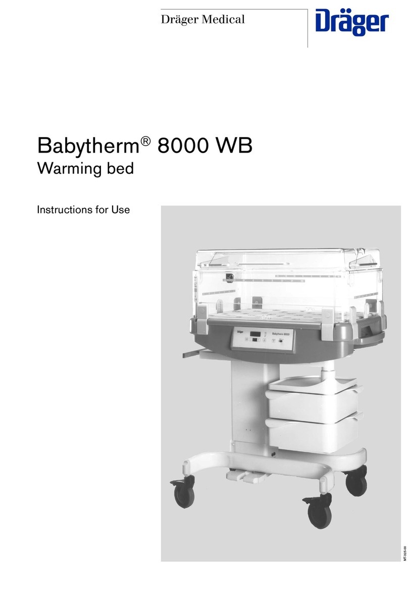
Dräger Medical Babytherm 8000 WB User manual

Dräger Medical

Dräger Medical Babytherm 8000 WB User manual

Dräger Medical Fabius GS Operating manual

Dräger Medical

Dräger Medical Fabius GS Operating manual

Dräger Medical Narkomed MRI-2 Assembly instructions

Dräger Medical

Dräger Medical Narkomed MRI-2 Assembly instructions

Dräger Medical Savina User manual

Dräger Medical

Dräger Medical Savina User manual

Dräger Medical Narkomed Mobile Assembly instructions

Dräger Medical

Dräger Medical Narkomed Mobile Assembly instructions

Dräger Medical Fabius GS Instruction Manual

Dräger Medical

Dräger Medical Fabius GS Instruction Manual

Dräger Medical Vapor 2000 User manual

Dräger Medical

Dräger Medical Vapor 2000 User manual

Dräger Medical Savina User manual

Dräger Medical

Dräger Medical Savina User manual

Dräger Medical RespiCare SC User manual

Dräger Medical

Dräger Medical RespiCare SC User manual

Dräger Medical Narkomed MRI Assembly instructions

Dräger Medical

Dräger Medical Narkomed MRI Assembly instructions

Dräger Medical Titus User manual

Dräger Medical

Dräger Medical Titus User manual

Dräger Medical Vamos Guide

Dräger Medical

Dräger Medical Vamos Guide

Dräger Medical Babytherm 8004 User manual

Dräger Medical

Dräger Medical Babytherm 8004 User manual

Popular Medical Equipment manuals by other brands

rayence 1012WCA user manual

rayence

rayence 1012WCA user manual

Bircher CareMat Ax1T T868.8 manual

Bircher

Bircher CareMat Ax1T T868.8 manual

Hewi 950 Mounting instructions

Hewi

Hewi 950 Mounting instructions

EMS AIRFLOW Prophylaxis Master Instructions for use

EMS

EMS AIRFLOW Prophylaxis Master Instructions for use

A&D UP-200 instruction manual

A&D

A&D UP-200 instruction manual

HEINE DELTA 20 Instructions for use

HEINE

HEINE DELTA 20 Instructions for use

Otto Bock 8320 Patella Pro Instructions for use

Otto Bock

Otto Bock 8320 Patella Pro Instructions for use

Merivaara PRACTICO Maintenance manual

Merivaara

Merivaara PRACTICO Maintenance manual

RoMedic hygienesling user manual

RoMedic

RoMedic hygienesling user manual

EKOM MEMBRANE DRYER Instructions for use

EKOM

EKOM MEMBRANE DRYER Instructions for use

Nasco Life/form LF01008U instruction manual

Nasco

Nasco Life/form LF01008U instruction manual

Gima Otoscope manual

Gima

Gima Otoscope manual

Welch Allyn Spot VS100 In-Service - Quick Reference Guide

Welch Allyn

Welch Allyn Spot VS100 In-Service - Quick Reference Guide

QT Medical QT ECG Recorder Troubleshooting

QT Medical

QT Medical QT ECG Recorder Troubleshooting

Mopec BD093 user manual

Mopec

Mopec BD093 user manual

Ambu AuraGain Instructions for use

Ambu

Ambu AuraGain Instructions for use

Defibtech Lifeline/ReviveR AUTO DDU-120 user manual

Defibtech

Defibtech Lifeline/ReviveR AUTO DDU-120 user manual

bort medical 103 301 quick guide

bort medical

bort medical 103 301 quick guide

manuals.online logo
manuals.online logoBrands
  • About & Mission
  • Contact us
  • Privacy Policy
  • Terms and Conditions

Copyright 2025 Manuals.Online. All Rights Reserved.