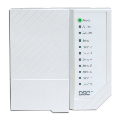
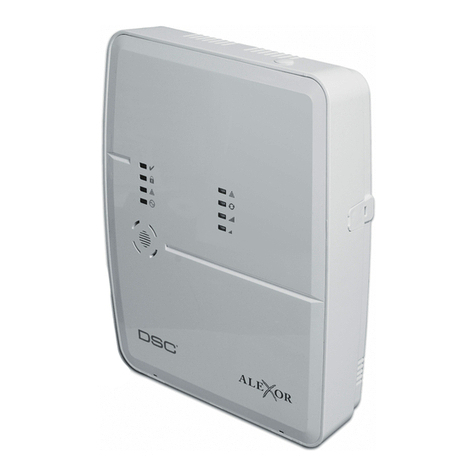
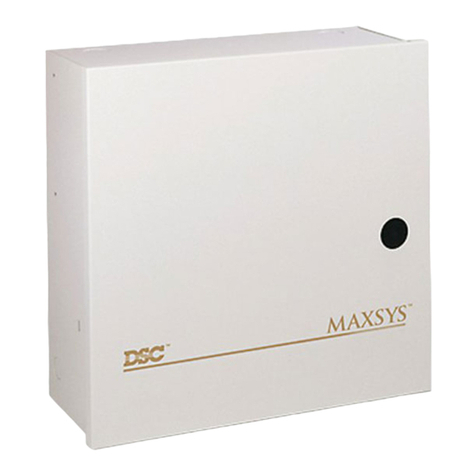
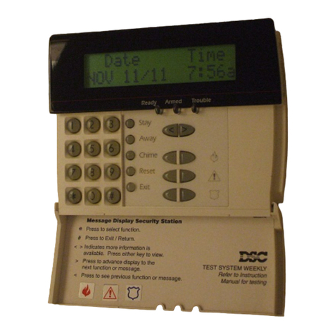
DSC PC2585 User manual

Installation
Manual
PC2585
• W A R N I N G •
This manual contains information on limitations regarding product use
and function and information on the limitations as to liability of the
manufacturer. The entire manual should be carefully read.
Software Version 1.1R
DLS-1 V6.2KR and up

LIMITED WARRANTY
Digital Security Controls Ltd. warrants the original purchaser that for a period of twelve
months from the date of purchase, the product shall be free of defects in materials and
workmanship under normal use. During the warranty period, Digital Security Controls
Ltd. shall, at its option, repair or replace any defective product upon return of the product
to its factory, at no charge for labour and materials. Any replacement and/or repaired
parts are warranted for the remainder of the original warranty or ninety (90) days, which-
ever is longer. The original owner must promptly notify Digital Security Controls Ltd. in
writing that there is defect in material or workmanship, such written notice to be received
in all events prior to expiration of the warranty period.
International Warranty
The warranty for international customers is the same as for any customer within Canada
and the United States, with the exception that Digital Security Controls Ltd. shall not be
responsible for any customs fees, taxes, or VAT that may be due.
Warranty Procedure
To obtain service under this warranty, please return the item(s) in question to the point of
purchase. All authorized distributors and dealers have a warranty program. Anyone re-
turning goods to Digital Security Controls Ltd. must first obtain an authorization num-
ber. Digital Security Controls Ltd. will not accept any shipment whatsoever for which
prior authorization has not been obtained.
Conditions to Void Warranty
This warranty applies only to defects in parts and workmanship relating to normal use. It
does not cover:
• damage incurred in shipping or handling;
• damage caused by disaster such as fire, flood, wind, earthquake or lightning;
• damage due to causes beyond the control of Digital Security Controls Ltd. such as
excessive voltage, mechanical shock or water damage;
• damage caused by unauthorized attachment, alterations, modifications or foreign objects;
• damage caused by peripherals (unless such peripherals were supplied by Digital Secu-
rity Controls Ltd.);
• defects caused by failure to provide a suitable installation environment for the prod-
ucts;
• damage caused by use of the products for purposes other than those for which it was
designed;
• damage from improper maintenance;
• damage arising out of any other abuse, mishandling or improper application of the
products.
Digital Security Controls Ltd.’s liability for failure to repair the product under this war-
ranty after a reasonable number of attempts will be limited to a replacement of the prod-
uct, as the exclusive remedy for breach of warranty. Under no circumstances shall Digital
Security Controls Ltd. be liable for any special, incidental, or consequential damages
based upon breach of warranty, breach of contract, negligence, strict liability, or any
other legal theory. Such damages include, but are not limited to, loss of profits, loss of
the product or any associated equipment, cost of capital, cost of substitute or replace-
ment equipment, facilities or services, down time, purchaser’s time, the claims of third
parties, including customers, and injury to property.
Disclaimer of Warranties
This warranty contains the entire warranty and shall be in lieu of any and all other
warranties, whether expressed or implied (including all implied warranties of mer-
chantability or fitness for a particular purpose) And of all other obligations or li-
abilities on the part of Digital Security Controls Ltd. Digital Security Controls Ltd.
neither assumes nor authorizes any other person purporting to act on its behalf to
modify or to change this warranty, nor to assume for it any other warranty or liabil-
ity concerning this product.
This disclaimer of warranties and limited warranty are governed by the laws of the
province of Ontario, Canada.
WARNING: Digital Security Controls Ltd. recommends that the entire system be com-
pletely tested on a regular basis. However, despite frequent testing, and due to, but not
limited to, criminal tampering or electrical disruption, it is possible for this product to
fail to perform as expected.
Installer’s Lockout
Any products returned to DSC which have the Installer’s Lockout option enabled and
exhibit no other problems will be subject to a service charge.
Out of Warranty Repairs
Digital Security Controls Ltd. will at its option repair or replace out-of-warranty prod-
ucts which are returned to its factory according to the following conditions. Anyone
returning goods to Digital Security Controls Ltd. must first obtain an authorization num-
ber. Digital Security Controls Ltd. will not accept any shipment whatsoever for which
prior authorization has not been obtained.
Products which Digital Security Controls Ltd. determines to be repairable will be repaired
and returned. A set fee which Digital Security Controls Ltd. has predetermined and which
may be revised from time to time, will be charged for each unit repaired.
Products which Digital Security Controls Ltd. determines not to be repairable will be
replaced by the nearest equivalent product available at that time. The current market
price of the replacement product will be charged for each replacement unit.
WARNING Please Read Carefully
Note to Installers
This warning contains vital information.As the only individual in contact with system users, it is your
responsibility to bring each item in this warning to the attention of the users of this system.
System Failures
This system has been carefully designed to be as effective as possible. There are circumstances, how-
ever, involving fire, burglary, or other types of emergencies where it may not provide protection. Any
alarm system of any type may be compromised deliberately or may fail to operate as expected for a
variety of reasons. Some but not all of these reasons may be:
nn
nn
nInadequate Installation
A security system must be installed properly in order to provide adequate protection. Every installation
should be evaluated by a security professional to ensure that all access points and areas are covered.
Locks and latches on windows and doors must be secure and operate as intended. Windows, doors,
walls, ceilings and other building materials must be of sufficient strength and construction to provide
the level of protection expected.A reevaluation must be done during and after any construction activity.
An evaluation by the fire and/or police department is highly recommended if this service is available.
nn
nn
nCriminal Knowledge
This system contains security features which were known to be effective at the time of manufacture. It
is possible for persons with criminal intent to develop techniques which reduce the effectiveness of
these features. It is important that a security system be reviewed periodically to ensure that its features
remain effective and that it be updated or replaced if it is found that it does not provide the protection
expected.
nn
nn
nAccess by Intruders
Intruders may enter through an unprotected access point, circumvent a sensing device, evade detection
by moving through an area of insufficient coverage, disconnect a warning device, or interfere with or
prevent the proper operation of the system.
nn
nn
nPower Failure
Control units, intrusion detectors, smoke detectors and many other security devices require an adequate
power supply for proper operation. If a device operates from batteries, it is possible for the batteries to fail.
Even if the batteries have not failed, they must be charged, in good condition and installed correctly. If a
device operates only by AC power, any interruption, however brief, will render that device inoperative
while it does not have power. Power interruptions of any length are often accompanied by voltage fluctua-
tions which may damage electronic equipment such as a security system. After a power interruption has
occurred, immediately conduct a complete system test to ensure that the system operates as intended.
nn
nn
nFailure of Replaceable Batteries
This system’s wireless transmitters have been designed to provide several years of battery life under normal
conditions. The expected battery life is a function of the device environment, usage and type. Ambient
conditions such as high humidity, high or low temperatures, or large temperature fluctuations may reduce the
expected battery life. While each transmitting device has a low battery monitor which identifies when the
batteries need to be replaced, this monitor may fail to operate as expected. Regular testing and maintenance
will keep the system in good operating condition.
nn
nn
nCompromise of Radio Frequency (Wireless) Devices
Signals may not reach the receiver under all circumstances which could include metal objects placed on or
near the radio path or deliberate jamming or other inadvertent radio signal interference.
nn
nn
nSystem Users
A user may not be able to operate a panic or emergency switch possibly due to permanent or temporary
physical disability, inability to reach the device in time, or unfamiliarity with the correct operation. It is
important that all system users be trained in the correct operation of the alarm system and that they
know how to respond when the system indicates an alarm.
nn
nn
nSmoke Detectors
Smoke detectors that are a part of this system may not properly alert occupants of a fire for a number of
reasons, some of which follow. The smoke detectors may have been improperly installed or positioned.
Smoke may not be able to reach the smoke detectors, such as when the fire is in a chimney, walls or roofs,
or on the other side of closed doors. Smoke detectors may not detect smoke from fires on another level of
the residence or building.
Every fire is different in the amount of smoke produced and the rate of burning. Smoke detectors cannot
sense all types of fires equally well. Smoke detectors may not provide timely warning of fires caused by
carelessness or safety hazards such as smoking in bed, violent explosions, escaping gas, improper storage
of flammable materials, overloaded electrical circuits, children playing with matches or arson.
Even if the smoke detector operates as intended, there may be circumstances when there is insufficient
warning to allow all occupants to escape in time to avoid injury or death.
nn
nn
nMotion Detectors
Motion detectors can only detect motion within the designated areas as shown in their respective installa-
tion instructions. They cannot discriminate between intruders and intended occupants. Motion detectors
do not provide volumetric area protection. They have multiple beams of detection and motion can only be
detected in unobstructed areas covered by these beams.They cannot detect motion which occurs behind
walls, ceilings, floor, closed doors, glass partitions, glass doors or windows. Any type of tampering whether
intentional or unintentional such as masking, painting, or spraying of any material on the lenses, mirrors,
windows or any other part of the detection system will impair its proper operation.
Passive infrared motion detectors operate by sensing changes in temperature. However their effective-
ness can be reduced when the ambient temperature rises near or above body temperature or if there are
intentional or unintentional sources of heat in or near the detection area. Some of these heat sources
could be heaters, radiators, stoves, barbeques, fireplaces, sunlight, steam vents, lighting and so on.
nn
nn
nWarning Devices
Warning devices such as sirens, bells, horns, or strobes may not warn people or waken someone sleeping if
there is an intervening wall or door. If warning devices are located on a different level of the residence or
premise, then it is less likely that the occupants will be alerted or awakened. Audible warning devices may be
interfered with by other noise sources such as stereos, radios, televisions, air conditioners or other appliances,
or passing traffic. Audible warning devices, however loud, may not be heard by a hearing-impaired person.
nn
nn
nTelephone Lines
If telephone lines are used to transmit alarms, they may be out of service or busy for certain periods of
time. Also an intruder may cut the telephone line or defeat its operation by more sophisticated means
which may be difficult to detect.
nn
nn
nInsufficient Time
There may be circumstances when the system will operate as intended, yet the occupants will not be
protected from the emergency due to their inability to respond to the warnings in a timely manner. If the
system is monitored, the response may not occur in time to protect the occupants or their belongings.
nn
nn
nComponent Failure
Although every effort has been made to make this system as reliable as possible, the system may fail to
function as intended due to the failure of a component.
nn
nn
nInadequate Testing
Most problems that would prevent an alarm system from operating as intended can be found by regular
testing and maintenance. The complete system should be tested weekly and immediately after a break-
in, an attempted break-in, a fire, a storm, an earthquake, an accident, or any kind of construction
activity inside or outside the premises. The testing should include all sensing devices, keypads, con-
soles, alarm indicating devices and any other operational devices that are part of the system.
nn
nn
nSecurity and Insurance
Regardless of its capabilities, an alarm system is not a substitute for property or life insurance. An alarm
system also is not a substitute for property owners, renters, or other occupants to act prudently to prevent
or minimize the harmful effects of an emergency situation.

55
TABLE OF CONTENTS
i
SPECIFICATIONS 1
FEATURES 2
INSTALLATION 3
Bench Testing ........................................................................................................................................................ 3
Zone Connections for Bench Testing .................................................................................................................... 3
Mounting the Panel ................................................................................................................................................ 4
Hook-up Procedure................................................................................................................................................ 4
Terminal Connections ............................................................................................................................................ 4
Keypad Installation ................................................................................................................................................ 6
Power-up Procedure .............................................................................................................................................. 6
Testing The System................................................................................................................................................ 6
Instructing End-User .............................................................................................................................................. 6
GUIDELINES FOR LOCATING SMOKE DETECTORS 7
KEYPAD FUNCTIONS 8
Introduction ............................................................................................................................................................ 8
Master Code........................................................................................................................................................... 8
Second Master Code ............................................................................................................................................. 8
Installer’s Programming Code ...............................................................................................................................8
Arming.................................................................................................................................................................... 8
Disarming ............................................................................................................................................................... 8
Auto Bypass/Home Away Arming.......................................................................................................................... 8
Bypass Zones ..................................... [Q]+[1] ..................................................................................................... 9
Display Trouble Conditions................. [Q]+[2] ..................................................................................................... 9
Alarm Memory Display........................ [Q]+[3] ................................................................................................... 10
Switched Auxiliary Supply Control...... [Q]+[Hold Down 4] ................................................................................ 10
User Programming Command ............ [Q]+[5]+[Master Code].......................................................................... 10
User Functions Command .................. [Q]+[6]+[Master Code].......................................................................... 11
Setting the Clock ........................... [Q]+[6]+[Master Code]+[1]................................................................... 12
Auto-Arm Time of Day ................... [Q]+[6]+[Master Code]+[2]................................................................... 12
Auto Disarm Time of Day............... [Q]+[6]+[Master Code]+[3]................................................................... 12
Quick-Arm ..................................... [Q]+[6]+[Master Code]+[4]................................................................... 12
Auto-Arm Enable ........................... [Q]+[6]+[Master Code]+[5]................................................................... 12
Door Chime ................................... [Q]+[6]+[Master Code]+[6]................................................................... 12
Arm / Disarm Memory.................... [Q]+[6]+[Master Code]+[7]................................................................... 12
System Test ................................... [Q]+[6]+[Master Code]+[8]................................................................... 12
User Call-up .................................. [Q]+[6]+[Master Code]+[9]................................................................... 12
Utility Output Command ................ [Q]+[7]+[1 or 2]+[Access Code] .......................................................... 13
Installer’s Programming Command .... [Q]+[8]+[Installer’s Code] ..................................................................... 13
At-Home Arming.................................. [Q]+[9]+[Access Code]......................................................................... 13
Quick-Arm Command ......................... [Q]+[0] ................................................................................................... 13
Quick Exit Command .......................... [Q]+[0] When Armed ............................................................................. 13
Keypad Zones...................................................................................................................................................... 13
PRINTER SET-UP 14
Compatible Printers ............................................................................................................................................. 14
Configuring the Printer ......................................................................................................................................... 14
Programming the Panel for Use with a Printer..................................................................................................... 15
DOWNLOADING 16
PROGRAMMING GUIDE 17
Introduction .......................................................................................................................................................... 17
Programming........................................................................................................................................................ 17
Reviewing Programmed Data .............................................................................................................................. 17
Sections [20] through [26], [44] and [49] ............................................................................................................ 17
Binary Data Display ............................................................................................................................................. 17
HEX Data Programming ....................................................................................................................................... 17
[00] Binary Programming..................................................................................................................................... 18
[01] First Telephone Number ...............................................................................................................................18
[02] First Account Code.......................................................................................................................................18

56ii
[03] Second Telephone Number ......................................................................................................................... 18
[04] Second Account Code ................................................................................................................................. 18
[05] Third Telephone Number..............................................................................................................................18
[06] Third Account Code .....................................................................................................................................18
[07] to [17] Reporting Code Explanation............................................................................................................. 18
[07] Alarm Reporting Codes, Zones 1 - 8............................................................................................................ 19
[08] Restoral Reporting Codes, Zones 1 - 8........................................................................................................ 20
[09] Tamper Alarm Reporting Codes, Zones 1 - 8 .............................................................................................. 20
[10] Tamper Restoral Reporting Codes, Zones 1 - 8 ..........................................................................................20
[11] Closing Reporting Codes, Access Codes 1 - 8 ........................................................................................... 20
[12] Closing Reporting Codes, Access Codes 9 - 16 ......................................................................................... 20
[13] Opening Reporting Codes, Access Codes 1 - 8 .........................................................................................20
[14] Opening Reporting Codes, Access Codes 9 - 16 .......................................................................................20
[15] Priority Alarm and Restoral Reporting Codes .............................................................................................. 21
[16] Maintenance Alarm Reporting Codes .......................................................................................................... 21
[17] Maintenance Restoral Reporting Codes ...................................................................................................... 21
[18] Zone Definitions............................................................................................................................................22
[19] System Times ............................................................................................................................................... 23
[20] First System Option Code.............................................................................................................................23
[21] Second System Option Code .......................................................................................................................24
[22] Third System Option Code ........................................................................................................................... 24
[23] Fourth System Option Code ......................................................................................................................... 25
[24] Fifth System Option Code.............................................................................................................................25
[25] Sixth System Option Code............................................................................................................................26
[26] Seventh System Option Code ......................................................................................................................27
[27] Maximum Dialing Attempts per Buffer..........................................................................................................27
[28] Swinger Shutdown and Transmission Delay / Bell Delay............................................................................. 28
[29] Communications Format...............................................................................................................................28
[30] Communicator Call Direction Options.......................................................................................................... 31
[31] PO1, PO2 and AUX-IN Input Options........................................................................................................... 31
[32] System Clock Times ..................................................................................................................................... 32
[33] Master Code ................................................................................................................................................. 32
[34] Second Master Code.................................................................................................................................... 32
[35] Installer’s Code.............................................................................................................................................32
[36] Bypass Mask, Zones 1 - 8 ............................................................................................................................33
[37] Access Code Bypass Mask, Access Codes 1 - 8 .......................................................................................33
[38] Access Code Bypass Mask, Access Codes 9 -16 ......................................................................................33
[39] Keypad Lockout Options..............................................................................................................................33
[40] - [43] Split Arming......................................................................................................................................... 33
[40] Group A Zone Assignment ...........................................................................................................................33
[41] Group B Zone Assignment ...........................................................................................................................33
[42] Group A Access Code Assignment .............................................................................................................33
[43] Group B Access Code Assignment .............................................................................................................33
[44] Number of Rings Before Answer and Downloading Configuration.............................................................. 34
[45] Double Call Timer ......................................................................................................................................... 34
[46] Panel Identification Code .............................................................................................................................34
[47] Downloading Access Code.......................................................................................................................... 34
[48] Downloading Telephone Number ................................................................................................................ 35
[49] Printer Configuration.....................................................................................................................................35
[50] Printer Language Option .............................................................................................................................. 35
[89] Print Event Buffer .......................................................................................................................................... 35
[90] Installer Lockout Enable ............................................................................................................................... 36
[91] Installer Lockout Disable .............................................................................................................................. 36
[99] Factory Default ............................................................................................................................................. 36
FOR THE RECORD 37
PROGRAMMING WORKSHEETS 38
KEYPAD AND FIRE CIRCUIT WIRING INFORMATION 49
HOOK-UP DIAGRAM 50

1
SPECIFICATIONS
Control Panel Specifications
12 zones including:
•8fullyprogrammablesupervisedzones(EOLresistors)
including Fire Zone capability
•1 auxiliary normally open zone
•3 keypad activated zones
Audible alarm output:
•Bell output
•700 mA, fused at 5 Amps, 12 VDC
•Steady or pulsed output
•Normal or inverted output
EEPROM memory:
•Does not lose codes or system status on complete AC
and battery failure
4 Programmable outputs:
•Transistor switch sinks 50 mA to ground. Operation
controllable through program options
•Powerful 1.5 amp regulated power supply:
•400 mA auxiliary supply, 12 VDC
•Separately fused for battery, keypad/auxiliary supply
and bell output
•Supervision for loss of AC power, low battery
•Internal clock locked to AC power frequency
Switched Smoke Detector Supply Output:
•Controlled from keypad [Q][4] command
Battery required:
•12 volt 4 Ah minimum rechargeable gel-cell or sealed
lead-acid battery
Transformer required:
•16.5 VAC, 40VA
Dimensions:
•11" × 11.8" × 3.3" deep (279 × 300 × 84 mm)
Weight:
•6.5 lbs (3 kg)
Remote Keypad Specifications
(PC2550RK)
•Four wire (QUAD) hook-up
•Nominal current draw: 60 mA
•Upto3keypadspersystem(recommended).Maximum
5keypads per system;refertoKeypad and FireCircuit
Wiring Information
•Built-in piezoelectric buzzer
•Full annunciation of zones and system status
•Dimensions 5.5" × 4.5" × 1" deep
(140 × 114 × 25 mm)
Output Voltage Specification
Typically, with normal AC in and a fully charged battery,
the output voltage will be 13.8 VDC. With AC off and a
discharged battery, the voltage will go to 10 volts.
Devicesthatrequirepowerfromthecontrolpanelshould
be capable of normal operation over the voltage range
of 10 to 14 VDC.
Digital Communicator Specifications
•92 reporting codes
•Transmits all 10 BPS and 20 BPS single line and
extended formats
•Radionics Rounds and Radionics Parity formats
•DTMF fast slot format
•4/3 DTMF with Parity
•Pager Format
•Sescoa Superspeed formats
•Private Line format
•3/1, 4/2 and hexadecimal numbers
•DTMF and Pulse dialing
•DPDT line seizure
•True dial tone detection
•Anti-jam feature
•3 telephone numbers and 3 account codes
•Split reporting of selected transmissions to each
telephone number

2
FEATURES
Keypad Programming
The PC2585 comes with a default program so it is
operational with a minimum of programming. It is
completely programmable from the keypad. The panel
usesEEPROMmemorysothatallinformationisretained
even if the panel loses both AC and battery power.
Multiple Level Static/Lightning
Protection
The PC2585 has been carefully designed and tested to
provide reliable service. It is built to take static and
lightning induced surges and keep on working. Multiple
level surge filters are on all zone inputs, the power
supply, the keypad connections, the bell output, the
auxiliary power supply and the telephone interface. A
special“ZAP-TRAC”circuitboardconfigurationcatches
high voltage impulses right at the wiring terminals.
Protective ground planes surround sensitive areas
preventing the spread of damaging voltage surges.
Metal Oxide Varistors (MOV’s) are placed in all the
critical areas to further reduce impulses to safe levels.
“Watchdog Monitor” Circuit
Even when all precautions are taken so that voltage
surges do not cause damage to the control panel, it is
possible to cause temporary disruption to the operation
of the microprocessor causing it to lose track of the
program sequence. The PC2585 is equipped with an
external “Watchdog Monitor” circuit which continually
checks the microprocessor program execution.
System Supervision Features
ThePC2585continuouslymonitorsanumberofpossible
trouble conditions including:
•Double end-of-line resistor zone supervision to allow
for both tamper and alarm detection
•An active battery supervision circuit that periodically
tests the battery under load.
•Keypad Tamper Supervision (with LED625T or
LCD600T keypads)
•A loss of the AC power supply.
•A supervised circuit trouble condition.
•A telephone line monitoring circuit.
•A bell circuit failure indicates open circuit or fuse
failure.
•A test code feature which transmits a communicator
test code to the monitoring station at a selected time
during the day. The test code can be sent at intervals
from 1 to 99 days. It can also be sent every hour on the
hour, or every 15 minutes.
•A bell/siren/communicator test feature which can be
activated from the keypad.
•TelephoneLineMonitoring(TLM)restoraltransmission.
•128-event Event Buffer
Zones Bypassed During Programming
•After entering the Installer‘s Programming Mode, all
zoneswillbebypasseduntilanAccessCodeisentered.
This feature allows all zone wiring to be completed
before the zones are activated.
Advanced Features
The PC2585 has many advanced features. Features
which provide the security system design flexibility and
selling advantage necessary to win those demanding
jobs and make them profitable.
Some of these features include:
•EEPROM memory retains all data even on complete
AC and battery failure. Panel powers up in last armed
or disarmed state before power loss.
•All programmable zones may be selected as one of 10
differenttypesincluding;delay,auxiliarydelay,instant,
interior, interior delay, interior with Home Away, delay
with Home Away, and 3 types of 24-hour emergency
and supervisory circuits.
•Keypad programming of up to 17 Access Codes.
•Zone bypassing from the keypad.
•Individual zone and system function indicators on
keypad.
•2keypadactivatedutilityoutputfunctionsforoperating
lights, door openers, cameras or other devices.
•Optional keypad LED status timeout as an energy
saver.
AlthoughthePC2585hasmanyfeatures,itisnotdifficult
touse.Allkeypadcommandsaresimilarandareassisted
by audible and visual cues.

3
INSTALLATION
Bench Testing
The PC2585 contains a factory default program. Any additional programming required can be done through the
keypad. For many applications all that will be required is to enter the telephone number and alarm codes with keypad
entries that are as straight forward as dialing a telephone number. If you need help talk to your DSC equipment
distributor.
The following items are required for bench testing:
•1 Single Pole Single Throw (SPST) switch,
•1 Single Pole Double Throw Centre-off (SPDT) switch
•2 5600Ωresistors.
Bench Testing Set-up
•One of the outer leads (A) of the SPST switch is connected to the “COM” terminal closest to the zone you are
working on.
•The common lead of the SPST (B) is shorted to the outer lead (D) of the SPDT switch.
•One 5600Ωresistor is connected between the two outer leads of the SPDT switch (D to F).
•The other 5600Ωresistor is connected from the common lead to the outer lead of the SPDT (E to F).
•The common lead of the SPDT switch (E) goes to the zone terminal you are working on.
The normal condition exists when the SPST switch is shorting leads A to B and the SPDT switch is shorting leads
E to F. These are the zone status conditions and switch settings:
•Switch 1 on AB and switch 2 on EF is a restoral condition (5600 Ohms).
•Switch 1 on AB and switch 2 on EE is an Alarm condition (11200 Ohms).
•Switch 1 on BC is a Tamper condition (open).
•Switch 2 on DE is a Tamper condition (short).
Zone Connections for Bench Testing
Connect the four keypad wires to the control panel as shown in the Hook-up Diagram in the back of this manual.
To completely test the PC2585 including the communicator data, it is necessary to connect the panel to a digital
receiver through a telephone line connection or by connecting the telephone terminals on the PC2585 to a digital
communicator test set such as the DSC DTS-1. The DSC DTS-1 digital communicator test set is an inexpensive unit
which can simulate the telephone system dial tone and the receiver hand shake and kiss-off tones as well as display
thedatasentoutbyadigitalcommunicator.Also,theDTS-1hasa“listen-in”featurewhichmakesitidealformonitoring
the transmission between communicator and receiver when the PC2585 is connected to the telephone line.
If you are using a DTS-1, connect the red and green telephone clips to the “A” and “B” terminals and connect the red
and black power clips to the “AUX [+]” and “AUX [-]” terminals on the PC2585. When power is applied to the panel
press the red local-line button on the DTS-1 and observe the display window area. The “local-line” indicator should
be in the local position.
For testing purposes, so that the sound level is not too loud, connect a small buzzer to the “BELL [+]” and
“BELL [-]” terminals to indicate when the panel is in alarm.
Connect a 16.5 VAC, 40 VA transformer to the “AC” terminals. Before plugging in the transformer be sure the circuit
board is not resting on anything metallic which may cause a short.
NOTE: THE PC2585 WILL NOT START UP IF “AC” IS OFF.

4
Whenthetransformerispluggedinthereshouldbelightsonthekeypadandthebuzzerconnectedtothebellterminals
maygoONfor afewseconds.The“Armed” lightmaybeONor OFFthefirsttimethe panelispowered.Thelast armed/
disarmed condition is stored in the EEPROM memory so the panel will always power up in the last armed/disarmed
state. If the “Armed” light is ON, enter the default Master Code [1234] to disarm the panel. If the keypad is not active,
check for the presence of AC power at the “AC” terminals, check the keypad connections and check the panel fuses.
If all the zones are properly connected with double end of line resistors all of the Zone Lights will be OFF. Note that
the panel will arm only if all zones are properly connected with double end of line resistors so that the “Ready” light
is ON. NOTE: The Fire Zone only requires a single end-of-line resistor. The keypad should beep several times to
indicate acceptance of the Master Code. Enter the Master Code to arm or disarm the panel.
Read the “Keypad Functions” section of this manual or the “End User’s Manual” and enter commands on the keypad
to become familiar with the different commands.
Turn to the “Programming Guide” in this manual and enter a sample program into the panel through the keypad to
become familiar with the programming commands.
Mounting the Panel
Select a dry location close to an unswitched AC source, close to a ground connection and close to the telephone
connection.
Removeprintedcircuitboard, mountinghardwareand keypadfromcardboard retainerinsidepanel.Beforeattaching
cabinet to wall, press the five white nylon printed circuit board mounting studs and the ground connection screw into
cabinet from the back.
Pull all cables into cabinet and prepare them for connection before mounting the circuit board to the back of the
cabinet. Press circuit board down onto mounting studs.
Hook-up Procedure
DO NOT connect transformer or battery until all other wiring has been connected. See power-up procedure.
Connecta ground cable from the cabinet groundconnectionbytheshortestandmost direct route to a grounding rod.
Connect zone cables to zone inputs and put double end of line resistors on any unused zones. Connect power wires
for motion detectors to the auxiliary supply.
Install keypads and connect wires to keypad terminals on panel. Connect RJ31-X cord to telephone terminals. Do not
insert plug into RJ31-X jack.
Connect bell or siren to “BELL [+]” and “BELL [-]” terminals. Observe correct polarity for sirens and polarized bells.
Connect 1000Ω½W resistor across terminals to eliminate trouble condition if bell circuit is not being used.
Terminal Connections
AC Power Terminals
Use a 16.5 VAC transformer with a minimum 40 VA rating to supply AC power to the PC2585. The transformer should
notbeconnectedtoanoutletthatiscontrolledbyaswitch.IfACfailureoccursitisdisplayedasatroubleonthekeypad
(see “Keypad Functions, [Q][2] Trouble Conditions”). It can also be transmitted to the monitoring station as a trouble
condition (see “Programming Guide [Q][8]” sections [16] and [17] for alarm and restoral codes and Section [19] for
AC transmission delay).
Auxiliary Power Terminals: AUX+ and AUX-
Two “AUX” terminals are provided to ease wiring congestion at these terminals. The auxiliary power supply can be
used to power motion detectors and other devices requiring 12 VDC. 400mA 12 VDC is available from the “AUX+”
(positive) and “AUX-” (negative) terminals when the PC2585 is used with one keypad. For each additional keypad the
auxiliary supply rating must be reduced by 60mA. The auxiliary supply is fused with the keypad supply at 1 amp.
Auxiliary fuse failure can be transmitted (see [Q][8] sections [16] and [17]).
Switched Auxiliary Power Terminals: SW AUX and AUX-
Theswitched auxiliary supply can be switched off momentarily from the keypad (see “Keypad Functions [Q][4]”). The
“SW AUX” terminal is positive and the “AUX-” terminal negative. The 400 mA auxiliarysupply rating must be reduced
by any current taken from the switched auxiliary supply. The switched supply shares the same fuse as the auxiliary
supply.
Bell/Siren Terminals BELL [+] and BELL [-]
These terminals are for powering bells or other devices requiring a steady output voltage on alarm. The bell output
isfusedfor5amps.Whenconnectingsirens(speakerswithsirendriveralreadybuilt-in),besuretoobservethecorrect
polarity. Connect the positive lead to the BELL [+] terminal and the negative lead to the BELL [-] terminal.

5
Ifnosirenorbellisused,connecta1000Ωresistor between BELL [+] to BELL[-].Thebell/sirenalarmoutputispulsed
(1 second ON 1 second OFF) when an alarm is created by the [F] keypad zone, by the FIRE zone, or when the Bell
Pulse option is enabled in Section [21] Zone Light 6. The Bell output can also be programmed to be inverted; refer
to Programming Section [21] Zone Light 7.
Keypad Terminals: RED, BLK, YEL and GRN
Connectthefourcoloredwiresfromthekeypadstotheseterminals.Whenconnectingmorethanonekeypad,connect
inparallelacrossthekeypadterminalsatthecontrolpanel(i.e.allredstogether,allblackstogether,allyellowstogether
and all greens together). The keypad red and black power supply terminals are fused through the auxiliary fuse.
Programmable Outputs: PO1, PO2, PO3 and PO4
ThePC2585provides4programmableoutputs.TheoperationofPO1andPO2dependsuponwhichoptionisselected
in the programming table. See the Programming Section [31]. PO3 and PO4 can be programmed for different
operations in the “Third System Option Code” Section [22]. Terminals PO1 to PO4 are 50mA maximum switches to
ground.A100Ohmcurrentlimitingresistorisconnectedinseries.Asmallrelay,abuzzerorotherDCoperateddevice
may be connected between the 12VDC “AUX+” (positive) terminal and any one of the “PO” (switched negative)
terminal on the main board.
Auxiliary Input Terminal: AUX IN (also Key Arming)
The “AUX IN” input terminal is a normally open 24-hour zone. It can be programmed from the keypad to be silent or
audible.Thereisnodisplayonthekeypadforthe“AUXIN”input.Analarmonthisinputiscreatedbyapplyingapositive
voltage or by closing a contact between the “AUX IN” terminal and the positive auxiliary supply. See “Programming
Guide [Q][8]” Section [15] for programming the alarm and restoral codes.
The “AUX IN” terminal can also be used as a momentary key arming/disarming input. See “Programming Guide”
Section [31] for a list of options for the “AUX IN” terminal.
Zone Input Terminals Z1 to Z8
Zone inputs Z1 to Z8 are supervised Double End Of Line resistor circuits. Double E.O.L resistor circuits give zones
the capability to detect tamper conditions. A tamper condition can be either a short or open on a zone. The normal
condition is 5600 Ohms. The Alarm condition is 11200 Ohms. The tamper resistor is placed between the tamper
contact and the alarm contact. This configuration will allow the panel to detect zone tampers (zone open or shorted),
zones in alarm (alarm condition of 11200 Ohms), and restored zones (normal condition of 5600 Ohms). See the
Hook-up Diagram for normally closed and normally open contact connections.
Telephone Terminals: A, B, C, D, and EGND
The wires from the RJ31-X telephone jack are connected to these terminals in the following way.
A Red wire from RJ31-X cord Incoming line from
B Green wire from RJ31-X cord telephone company
C Grey wire from RJ31-X cord Outgoing line to
D Brown wire from RJ31-X cord house telephone(s)
Battery Connections
Do not connect the battery or the transformer until the wiring is complete. Connect the red battery lead to the positive
battery terminal and the black lead to the negative battery terminal. If the connection is made in reverse the battery
fuse will blow. The battery charging voltage is factory set and normally needs no adjustment.

6
Keypad Installation
Mount the keypads near the exit-entry doors. The PC2550RK keypad has a red, a black, a green and a yellow wire
on the back. Connect these four wires to the four keypad terminals on the control panel using four conductor (quad)
telephone wire. Up to three keypads may be connected to one PC2585. Connect all green wires from the keypads to
the“GRN” terminalonthepanel.Connectallyellowwiresfromthekeypadstothe“YEL”terminalonthepanel.Connect
all red wires from the keypads to the “RED” terminal. Connect all black wires from the keypads to the “BLK” terminal.
The following DSC keypads are also compatible with the PC2585:
• LED625
• LED625T
• LCD600
• LCD600T
Consult your DSC dealer for information regarding these keypads and required software versions.
Power-up Procedure
If the keypads are located a distance from the panel, install an extra keypad temporarily at the panel during power
up testing. An extra keypad with a short length of cable and alligator clips attached is helpful for testing and
programming PC2585 systems.
Connect the transformer and wait approximately 5 seconds.
Enter a few keypad commands and open a zone to be sure that the panel and keypad are responding to signals. If
the keypad does not respond and there are no indicators ON, check for AC voltage at the “AC” terminals. If there is
16 VAC present, check that the keypad wiring is correct and check the keypad/auxiliary supply fuse. If the keypad/
auxiliary supply fuse is blown check for a short between the keypad red and black wires before replacing the fuse.
If the keypad is responding normally, connect the battery. The red battery lead attaches to the positive battery post
and the black battery lead attaches to the negative battery post.
NOTE: THE PC2585 WILL NOT START UP IF ‘AC’ IS OFF.
Testing The System
SeeInstaller’stest,[Q][6][MasterCode][0],ordothefollowing.Contactthemonitoringstationtorequestatransmission
test. Plug the telephone cord into the RJ31-X jack. If a DTS-1 is being used to monitor communicator transmissions,
connect as described in “Bench Testing” section and place the DTS-1 in the line mode by pressing the red “LINE/
LOCAL” button. Arm the panel, wait for the exit delay to expire and trip a detector on an instant circuit. Wait for the
communication to complete. Disarm panel and check with the monitoring station to confirm the transmission. Perform
additional transmissions required by the monitoring station.
Check the “Trouble” light; if it is ON, press [Q] then [2] to determine if there is a system trouble. The “Trouble Display”
section in “Keypad Commands” gives a description of the different trouble conditions.
Instructing End-User
Fill out the system reference guide in the PC2585 End User’s manual. Check off sections in the manual which apply
to the user’s system and make additional notes if necessary.
Describe the system to an authorised user. Describe arming and disarming procedures. Describe the basic keypad
functions. Assist the user in working through examples of each type of command.
Providetheuser(s)withtheinstructionmanualandinstructthemtoreadthemanualtobecomefamiliarwiththesystem
operation.
Instruct the user to test the system on a regular basis as described in the user manual. The Master Code should be
changed from the default setting and recorded in the End User Manual.

7
Bedroom Bedroom
Bedroom
Living RoomKitchen
Family Room
Bedroom
Living
Room
Dining
Room
Kitchen
Bedroom
Bedroom
Bedroom Bedroom
Basement
Living
Room Dining
Room
NEVER
HERE
Acceptable
here
Top of detector
acceptable here
12"
(0.3m)
Max.
4"
(0.1m)
Max.
4"
(0.1m)
Ceiling
Wall
NOTE: Measurements shown are to
the closest edge of the detector.
GUIDELINES FOR LOCATING SMOKE DETECTORS
Experiencehasshownthatallhostilefiresinfamilyliving
units generate smoke to a greater or lesser extent.
Experiments using typical fires in family living units
indicate that detectable quantities of smoke precede
detectable levels of heat in most cases. For these
reasons,smoke detectors should beinstalledoutsideof
each sleeping area and on each additional story of the
family unit.
The following information is for general guidance only
and it is recommended that the smoke detector
manufacturer'sliteraturebeusedfordetailedinstallation
instructions.
It is recommended that additional smoke detectors
beyond those required be installed for increased
protection. The added areas include: basement,
bedrooms, dining rooms, furnace room, utility room and
hallways not protected by the required detectors.
Figure 1: A smoke detector should be located between
the sleeping area and the rest of the family unit.
Figure 2: In family living units with more than one
sleeping area, a smoke detector should be located to
protect each sleeping area.
Figure 3: A smoke detector should be located on
each story of the living unit.
Figure 4: Smoke Detector mounting and “Dead” Air
Space. The smoke from a fire generally rises to the
ceiling, spreads out across the ceiling surface and
begins to bank down from the ceiling. The corner
where the ceiling and wall meet is an air space into
which the smoke may have difficulty penetrating. In
most fires, this “dead” air space measures about 4 in.
(0.1m) along the ceiling from the corner and about 4 in.
(0.1m) down the wall as shown in Figure 4. Detectors
should not be placed in the “dead” air space.

8
KEYPAD FUNCTIONS
Introduction
ThePC2550RKremotekeypadprovides completeinformationand controlofthe PC2585controlpanel. Thepanelcan
be fully programmed from the keypad. The 8 Zone Lights and the “Fire” light provide alarm and status indication for
the alarm circuits. The 6 function lights guide the user in operating the system. The built-in buzzer lets the user hear
correctkeyentriesandotheralertsignals.The12digitkeypadisusedforcodeentryandotherprogrammingfunctions.
All keypad entries are made by pressing one key at a time.
The keypad is normally resting in the arm-disarm mode. In this condition the Zone Lights are indicating the opening
and closing of zones.The Ready LIGHT comes ONwhen allzones are closed. Thesystem can bedirected to perform
other functions such as zone bypassing, displaying trouble conditions, displaying alarm memory and programming
by entering one of the various [Q] commands described below. Pressing the [#] key or not making any key entry for
2 minutes returns the keypad to the arm-disarm mode.
Master Code
A default Master Code “1234” is programmed into the PC2585 at the factory. The Master Code is used for arming and
disarming the control panel, for programming up to fifteen additional Access Codes using the [Q][5] command and
for entering other userfunctions using the [Q][6] command.The Master Codecan bereprogrammed by the userif the
installerprograms itthat way(Section [23]Zone Light5). ThePC2585 usesEEPROM memoryand thecodesand other
data are retained even after complete AC and battery failure.
Second Master Code
A second Master Code can be programmed into the PC2585; in the default setting, the Second Master Code is not
programmed. This code can be changed by the installer only. The Second Master Code is useful where there are
multiplepanelsina complex,wherethe codecanbe usedasa“masterkey”. Notethatthe sameClosingand Opening
Codes are transmitted for both the Second Master Code and the regular Master Code.
Installer’s Programming Code
A default installer’s programming code “2585” is programmed into the PC2585. This code is used with the [Q][8]
command by the installer to gain access to the system in order to enter panel or communicator program information.
The installer’s program code may be changed by the installer.
Arming
Check to see if the “Trouble” or “Bypass” light is ON before arming the PC2585. Close all protected doors and
windows and stop movement in areas covered by motion detectors. Check to see that the “Ready” light is ON (all
zones are closed). The system cannot be armed unless the “Ready” light is ON. Enter a [4 Digit Access Code]. As
eachdigit is entered thekeypadbuzzerwill beep. If theAccessCodewasentered incorrectly, the sounderwillbeep
steadily for 2 seconds. If the code was entered correctly but the “Ready” light was not ON, the keypad will beep
quicklyfollowedbyasteadytone.Whenthecorrectcodeisentered,the“Armed”lightwillcomeONand the keypad
buzzerwill beepquickly.Exit thepremisesthrough the designatedexit-entrydoor. Attheend oftheallowedexit time
all lights on the keypad will go out except the “Armed” light. See Programming Section [19] for instructions on how
to change the exit time. Also see “Quick-Arm” and “At Home Arming”.
Disarming
Enter the premises through the designated exit-entry door; the keypad buzzer will be sounding a steady tone. Go
to the keypad and enter the [4 digit Access Code]. If an error is made entering the code, press the [#] key and enter
the code again. The “Armed” light will go out and the keypad sounder will stop. The correct Access Code must be
enteredbeforethe allowed entry time expires. Tochange the entry time, refer tothe Programming Guide. If an alarm
occurred while the panel was armed, the “Memory” light and the Zone Light which caused the alarm will start to
FLASH and continue flashing for 2 minutes when the panel is disarmed. Pressing the [#] key returns the panel to the
normal arm-disarm mode.
Auto Bypass/Home Away Arming
Ifacorrect Access Code is entered, andyou do not exit the premises,the system will, at the endofthe Exit delay time,
armwithinteriorzonesautomaticallybypassedifthoseinteriorzoneshavebeenprogrammedas“HomeAway”zones.
The “Bypass” light will come ON immediately following the arming code being entered until a delay zone is tripped
or [Q][1] is entered to reactivate bypassed Home Away zones (see Programming Section [18] Zone Definitions for
programming zones as “Home Away”).
This is a convenience feature for the user who wishes to remain at home with the system armed. The user does not
have to manually bypass the Home Away zones. To reactivate the Home Away zones that have been automatically
bypassed, press [Q][1]. The “Bypass” light will go out. This command is a quick method of fully arming the system
before retiring for the night.

9
Bypass Zones: [
Q
]+[1]
A bypassed zone will not cause an alarm; note that Tamper Alarms cannot be bypassed. If a zone is bypassed, the
systemmaybearmed (“Ready”lightwill beON)even ifthezoneisopen. Usezonebypassing whenaccessis needed
to part of the protected area.
To bypass zones, enter [Q][1] and the zone number(s) to be bypassed. Press [#] to return to “Ready” (arm-disarm
mode). When bypassing zones, one digit must be entered for each zone number(s) to be bypassed (for example,
[Q][1][1 to 8]). To remove all bypasses, enter [Q][1][0][#]. The Zone Lights which are ON while the “Bypass” light
is flashing indicate the bypassed zones. Remember that if no keypad entry is made for more than 2 minutes the
keypad will return to the arm-disarm mode. Then, in order to bypass a zone the complete command must be re-
entered. Once the bypass command is entered, pressing [9] recalls the last zone or group of zones which was
bypassed. If the same group of zones is bypassed each time, this bypass recall feature can be used instead of
having to bypass zones individually.
Whenthe PC2585 is programmed, the ability to bypass certainzones may be eliminated.In this case, the ZoneLights
for those zones will not come ON in response to the bypass command. Refer to Programming Section [36] for
instructions on programming the Bypass Mask. If the “Bypass” light is ON before arming the system, the [Q][1]
command should be used to see which zones are bypassed so that zones are not unintentionally bypassed. Zone
bypasses are automatically cancelled when the panel is disarmed.
IfZoneLight4 inSection[23]isON thenacodemustbe enteredwith[Q][1] tobypasszones.Onlythe zonesassigned
tothesamesideofthesystemastheAccessCodecanbebypassed.TheabilitytobypassusingcertainAccessCodes
can be eliminated. See the “Access Bypass Mask” instructions in Programming Sections [37] and [38].
NOTE: At no time can any armed zone be bypassed.
Display Trouble Conditions: [
Q
]+[2]
The PC2585 continuously monitors a number of possible trouble conditions. If one of these conditions occurs, the
“Trouble” light will come ON and the audible indication will sound (two short beeps every 10 seconds). When the
[#] key is pressed the audible indication will stop but the “Trouble” light will remain ON until the trouble is cleared.
Trouble conditions can also be transmitted to the monitoring station (see Programming Sections [16] and [17] for
alarmand restoral trouble codes). Press the [Q] then[2] keys to display thetype of trouble. The Zone Lightsindicate
the type of trouble condition:
1Low standby battery
2AC power failure
3Keypad Tamper trouble
4Telephone line trouble
5Unsuccessful communication attempt with monitoring station
6Bell circuit failure
7Smoke detector zone trouble
8Loss of time on internal clock
Press [#] to return to “Ready”.
1 Low Battery:
A battery trouble will be displayed and can be reported if the battery is weak, disconnected or the
battery fuse is blown. The low battery trouble display is latching and can only be cleared by correcting the low
battery condition and then entering an Access Code.
2 AC Power Failure: There is no audible annunciation onACpowerfailure.Thesystem“Trouble” light will come ON
but the audible indication will not sound until there is a low battery condition. An AC Failure Transmission Delay
can be programmed for 1 to 255 minutes. See “Programming Guide” Section [19].
3 KeypadTamperTrouble:TheKeypadTamperfunctionisenabledinSection[26]withZoneLight4.IftheLED625T
or LCD600T keypads are removed from their wall mounts, a keypad tamper will be annunciated and displayed on
thekeypad,andthe LCD600Twilldisplay themessage“Service RequiredCallInstaller”.Ifprogrammed inSection
[16], a Keypad Tamper Reporting Code will be transmitted. When a keypad tamper trouble is initiated, the system
may be disarmed but not armed. The “Ready” light will remain OFF until all keypads are returned to their mounting
plates and the [Q][8][Installer’s Code][#] command is entered to reset the system. Keypad Tampers will be
indicated with Zone Light 3, but Keypad Tampers will not be stored in the Trouble Memory. NOTE:NOTE:
NOTE:NOTE:
NOTE: The bell and
keypad sounder will not sound for Keypad Tampers.
4 Telephone Line Trouble: Atelephoneline trouble is generated when the linevoltagedropsbelow3voltsfor more
than30seconds.Itgeneratesakeypadtroublewhenthesystemisdisarmedandringsalocalalarmwhenthepanel
is armed. See Section [21] for options.

10
5 Unsuccessful Communication:
If the digital communicator is unsuccessful communicating with the monitoring
stationafter the maximumnumber of attemptsto each telephonenumber that isto be tried,a trouble isgenerated.
Ifa later attemptto communicate issuccessful the troubleis cleared. Thistrouble can alsobe cleared bypressing
the[#]keytoexitthetroubleviewmode.InSection[22]ZoneLight5,thetroublecanbeprogrammedtobeaudible
(bell will sound) or silent (bell will not sound)
6 Bell Circuit Failure:Ifthe bell fuse isblown or the bellcircuit is open, a keypad trouble and a trouble transmission
are generated.
7 Smoke Detector Zone Trouble: If a FIRE zone is open circuit, a keypad trouble and a trouble transmission are
generated.A trouble on theFIRE zone will unconditionally initiate an audible indication on the keypad. This means
that even if any other previous trouble has been silenced, a FIRE zone trouble will restart the keypad buzzer.
8 Loss of Internal Time:
When the PC2585 is powered up or reset, the internal time of day clock needs to be set
tothecorrecttime.Thistroubleisclearedwhenthetroubledisplayisviewedandexitedorwhenanattemptismade
to reset the internal time of day clock. See “[Q][6] User’s Function Commands” for resetting time of day clock.
If[9] is pressed while in the troubledisplaymodethemostrecenttrouble will be displayed on the ZoneLights.This
trouble memory feature is useful as a diagnostic aid when installing and servicing the PC2585.
Alarm Memory Display: [
Q
]+[3]
Press [Q] then [3] to enter the alarm memory mode. The “Memory” light will FLASH and any alarm caused during the
last armed period will be displayed on the Zone Lights. In addition to the last alarm memory there are 2 history levels.
After entering the memory mode (pressing [Q] then [3]), pressing [9] will cause the keypad to display the two other
levels of alarm history. Each time [9] is pressed the keypad will beep 1, 2 or 3 times to indicate which level of history
isbeing viewed. When the panel is armed, the last alarmmemory is cleared and the contents moves to the firsthistory
level. The “Memory” light will only be ON when there was an alarm during the last armed period. Press [#] to return
to “Ready”.
Switched Auxiliary Supply Control: [
Q
]+[Hold Down 4]
To interrupt the switched auxiliary power supply press [Q] then hold down [4] for the desired interrupt time. When the
[4] is released the system returns to the ready mode and the switched auxiliary supply is restored.
User Programming Command: [
Q
]+[5]+[Master Code]
The [Q][5] user’s programming commands are used to program additional Access Codes. Up to 16 user arm-disarm
codes may be programmed. The first code is the Master Code (factory default [1234]). The 16th code is optionally a
“One Time Use”. The 16th code may be changed from a “One Time Use” code to a regular code using an installer’s
programming command (Section [23] Zone Light 6). Remember if no keypad entry is made for more than 2 minutes
the keypad will return to the normal arm-disarm display and the complete command will have to be re-entered to
program a new Access Code.
Programming Additional Access Codes
11
11
1 Press the [Q] and [5] keys then enter the Master code (default [1234]) to enter the additional code programming
mode. The “Program” light and Zone Light 1 will be ON to show that the first code (the Master Code) is already
programmed with the factory default code [1234]. The Master Code may be changed but do not try to erase the
Master Code. The installer can disable user changing of the Master Code by turning Zone Light 5 in Section [23]
ON.
22
22
2 Seven additional codes may be programmed. The Zone Lights are used to indicate which of these codes are
alreadyprogrammed (zone ON steady) andtheonewhichis currently being programmed (ZoneLightisflashing).
33
33
3 To program the second code, press [2] and Zone Light 2 will FLASH. Then enter a 4 digit code and the buzzer will
beep three times and Zone Light 2 will come ON steady indicating a programmed code.
44
44
4 Toremovethesecondcode,press[2]-thebuzzerwillbeepthreetimesandZoneLight2willFLASH.Enter[QQQQ],
the buzzer will beep three times and Zone Light 2 will go out to show that the code has been removed.
55
55
5 Follow the instructions in 3 or 4 for programming or removing any of the other additional codes from 2 to 8.
66
66
6 To program Access Codes 9 to 16, press 9 to toggle into the upper code region. Zone Lights 1 to 8 now represent
Access Codes 9 to 16 (Zone Light 1 is code 9, Zone Light 8 is code 16). The ready and armed LED’s should flash
to indicate that the user is in the upper programming region. Program or remove Access Codes 9 to 16 as stated
in 3 and 4 above. Press 9 again to toggle back down to the lower region (Access Codes 1 to 8).

11
77
77
7 Do not try to remove the Master Code (first code). The Master Code may be changed but it must not be removed.
Whenchanging theMasterCode besureto enter avalid4 digitnumber(use onlynumberkeys0 to9).Do notenter
[#] or [Q] as one of the digits. If the Master Code is forgotten and the panel is left disarmed, program a new Master
Code using the [Q][8][Installer’s Code][33] command. If the Master Code is forgotten and the panel is left armed,
then the entire programming can be reset to factory default by using the Hardware Reset method described in
Programming Section [99].
88
88
8 To successfully program or remove additional codes, the panel must be put into the code program mode by
following step 1 followed by steps 3 or 4. Note that if no key entry is made for 2 minutes the panel will go back to
the normal arm/disarm mode, after which step 1 must be repeated to get back into the code program mode.
99
99
9 To exit the Access Code programming mode, press [#].
Programming a new Access Code:
[Q][5][Master Code][1 to 8][4 digit code]
or
[Q][5][Master Code][9][1 to 8][4 digit code]
Eliminating an existing Access Code:
[Q][5][Master Code][2 to 8][QQQQ]
or
[Q][5][Master Code][9][1 to 8][QQQQ].
NOTE: The Access Code numbers must be entered as one digit, that is, as [2], [3], [4], and so on.
User Functions Command: [
Q
]+[6]+[Master Code]
Thiscommandisusedtosetthesystemclocktimeanddate,andtosettheAuto-ArmandAuto-Disarm times. It is also
used to turn ON and OFF a number of system functions. The command is used by entering [Q][6][Master Code] then
a number from the following list to select the item to be changed:
[0] Installer’s test
[1] System 24-hour clock (enter HH:MM and DD/MM/YY)
[2] Auto-Arming time (enter HH:MM)
[3] Auto Disarm Time (HH:MM)
[4] Quick-Arm enable/disable
[5] Auto-Arm enable/disable
[6] Door Chime
[7] Arm / Disarm Memory
[8] System Test
[9] User Initiated Call-up
NOTE: Enter the time in the 24-hour clock format. Enter 00 to 23 for the hour, and 00 to 59 for the minute.
For the date, enter 01 to 31 for the day, 01 to 12 for the month, and 00 to 99 for the year. .
Items [1], [2] and [3] are time setting functions. Enter 4 digits representing the time in hours and minutes (HH:MM) in
the 24-hour clock format. Always enter a leading zero where only one digit is required, 8:05 am would be entered as
0805, 1:30 pm would be entered as 1330. Items [0], [4], [5] and [6] turn ON and OFF various features. When the item
key is pressed, the feature is turned ON if the keypad beeps quickly 3 times. The feature is turned OFF if the keypad
sounds one long beep. Pressing item [8] gives a 2 second bell and keypad light test. Pressing [9] makes the panel
call the Downloading computer if the User Initiated Call-Up Feature is enabled in Section [44].
Installer’s Test: [Q]+[6]+[Master Code]+[0]
This feature is designed to assist the installer in testing the system. In this mode, the bell or siren will operate for 2
seconds each time a device indicates an alarm condition. If the device indicates a tamper condition, the keypad
sounderwillbeactivatedfor2seconds.Inbothcases,theeventwillberecordedinthefirstlevelofmemory.Thefeature
isautomaticallydisabledwhenthe panelisarmed anddisarmed,or ifthe[Q][6][MasterCode][0]command isentered
again.Eachtimeazoneistrippedorrestoredinthismode,asignal,ifprogrammed,willbetransmittedtothemonitoring
station. If this is not desired, it is possible to disable the communicator during the test (see Section [20] “First System
Option Code”). A printer, if attached, will not function if the communicator is disabled.
NOTE: Do not use the PC16OUT module during the installer’s test.
Do not use the installer's test when the panel is partially armed.

12
Setting the Clock: [Q]+[6]+[Master Code]+[1]
Setting the “System 24-hour Clock” (item [1]) tells the system the correct time of day. If the system is without battery
andACpoweritcannotcontinuetokeeptime.Thereforewhenthepanelisfirstpowereduporwhenithasbeenwithout
AC power long enough to completely discharge the standby battery, the “System 24-hour Clock” must be reset. If the
timeneedstobereset,aTroubleconditionwillbeindicatedwithZoneLight8(see[Q][2]“SystemTroubleCommand”).
Setting the clock must include the day, month and year (e.g. HH : MM : DD : MM : YY).
Auto-Arm Time of Day: [Q]+[6]+[Master Code]+[2]
ThePC2585canbeprogrammedtoarmatthesametimeeachday.Programmingitem[2]setsthistimeandthefeature
must be enabled as shown in item [5] (see Auto-Arm Enable below).
The keypad will sound for one minute before the system auto-arms. At the end of the one-minute warning period, the
systemwillbearmed;notethattherewillbenoExitDelay.Auto-Armingmaybecancelledusingthefollowingmethods:
•Auto-Arm Abort: Any one key can be pressed to abort the Auto-Arm sequence and silence the keypad during the
oneminute pre-alert (this isthedefaultcondition). If Section [23]ZoneLight3is ON, then avalid4digit Access Code
is required to abort the Auto-Arm sequence. The Auto-Arm will be attempted at the same time the following day.
•Auto-Arm Abort with Transmission: Any time an Auto-Arm is aborted using one of the above methods, the Auto-Arm
abort reporting code programmed in Section [12] will be transmitted to the central station.
When the panel does arm by Auto-Arming, any open zones will be “Force-armed”. If Zone Light 2 in Section [23] is
ON, the panel will send a partial closing code to let the central station know zones were bypassed. If Section [23]
Zone Light 1 is ON, the zones that were bypassed will be identified by transmitting their alarm code along with the
partial closing code.
Auto Disarm Time of Day: [Q]+[6]+[Master Code]+[3]
The PC2585 can be programmed to disarm at the same time each day. In order for the panel to automatically disarm
at the time entered, program a valid time. To disable Auto Disarming, program an invalid time such as “9999”.
Quick-Arm:[Q]+[6]+[Master Code]+[4]
The “Quick-Arm” feature is enabled by pressing the [4] key while in the “User’s Function Commands” section. When
enabled (enabled 3 beeps....disabled one long beep) the panel can be armed by entering [Q][0]. The closing code
transmitted for “Quick-Arm” is the same as the code which is programmed for the Master Code.
Auto-Arm Enable: [Q]+[6]+[Master Code]+[5]
Entering [Q][6][Master Code][5] will enable/disable the Auto-Arming feature. When the feature is being Enabled, the
keypad buzzer will sound 3 beeps and when being Disabled the buzzer will sound one long beep.
Door Chime: [Q]+[6]+[Master Code]+[6]
The “Door Chime” feature is enabled by pressing the [6] key while in the “User’s Function Commands” section. When
enabledthekeypadbuzzerwillbeepquickly5timeseachtimeanyzoneprogrammedasaDoorChimetypeinSection
[18] opensor closes.The “Door Chime” featuredoes notoperate on otherzone definitions. Zonebypass maybe used
to eliminate “beeping” on doors where it is not wanted. This feature operates only while the panel is disarmed.
Arm / Disarm Memory: [Q]+[6]+[Master Code]+[7]
TheArm / DisarmMemory command displaysthe last AccessCode to armor disarm thesystem. When thecommand
is entered, the Access Codes are displayed on the Zone Lights. If more than one Zone Light is ON, add the zone
numbers to determine the Access Code (for example, if Zone Lights 2 and 8 are ON, Access Code 10 is indicated).
If Split Arming is disabled: the zone lights will display the last Access Code used to disarm the system. Press [9] to
display the last Access Code used to arm the system.
IfSplitArmingisenabled:thezonelightswilldisplaythelastAccessCodeenteredonthekeypad.Press[9]todisplay
the second last Access Code entered on the keypad.
System Test: [Q]+[6]+[Master Code]+[8]
The system test feature sounds the bell or siren, lights the keypad indicators and beeps the keypad buzzer for 2
seconds. If a Test Transmission Reporting Code is programmed in Section [17], it will be transmitted during the
System Test.
User Call-up:[Q]+[6]+[Master Code]+[9]
This function is enabled in Section [44]. When activated, the panel will call the downloading computer. The
downloading computer must be waiting for the panel to call before downloading can be performed.

13
Utility Output Command: [Q]+[7]+[1 or 2]+[Access Code]
The PC2585 can control two utility outputs (PO1 and PO2) from the keypad. These outputs can be used for operating
other devices such as; garage door openers, special lighting or door strikes. The programmable outputs must be
selected for keypad utility using the [Q][8][Installer’s Code][31] command and programming a [1].
To enable PO1, enter [Q][7][1][Access Code]; to enable PO2, enter [Q][7][2][Access Code]. When the command is
entered, the keypad sounder and the programmable output are activated for 5 seconds.
Installer’s Programming Command: [
Q
]+[8]+[Installer’s Code]
The PC2585 is completely programmable from the keypad by using commands in the [Q][8] section. The commands
are described in detail in the Programming Section of this manual.
At-Home Arming: [
Q
]+[9]+[Access Code]
Entering[Q][9]beforethearmingcode,armsthepanelwithoutanyentrydelayonthedelayzonesandbypasseszones
thataredefinedas“HomeAway”.Thiscommandisusedforarmingthesystemwhileathome.Whenthepanelisarmed
using [Q][9], the “Armed” light will FLASH and the “Bypass” light will be ON to indicate that the “Home Away” zones
are bypassed. Once the panel is Armed in this mode, using [Q][1] will remove the bypass from those zones defined
as “Home Away” if they have not been manually bypassed. The [Q][1] command used here, only removes the bypass
from zones that have been Automatically bypassed with the [Q][9] command.
Quick-Arm Command: [
Q
]+[0]
Entering [Q][0] is accepted as a valid arming code when the “Quick-Arm” feature is activated. This command is often
used when individuals are only required to ARM the system. These individuals will not be able to disarm the system.
This could be used with home visitors in the case of a residential alarm or junior employees and maintenance staff in
the case of a commercial alarm. See instructions in the “[Q][6] User’s Function Commands” section for activating the
“Quick-Arm”feature.ThisfeatureshouldnotbeenablediftheOneTimeUseCodeisenabled.TheOneTimeUseCode
must be used for arming before it is erased.
Quick Exit Command: [
Q
]+[0] When Armed
Entering[Q][0] whenthesystem isfullyarmed willallowthe user2minutes toexitthe premisesthroughany delayzone
without altering the status of the system if the quick exit feature is enabled. The quick exit feature can be enabled by
turning ON Zone Light 7 in Section [23]. After [Q][0] is entered into an armed system, one and only one delay zone
may be tripped. Any additional activity on any other active zone will cause that zone to begin its alarm sequence.
[Q][0] for Quick Exit on a partially armed system is not supported.
Quick Exit must not be used when auxiliary delay zones are force armed. Turn Zone Light 4 in Section [24] OFF to
ensure proper operation.
Keypad Zones
IMPORTANTNOTE: Whilethe Installer’s ProgrammingMode is active,the [F], [A]and [P]keyswill bebypassed
until the Programming Mode is exited and an Access Code is entered.
There are three zones which can be activated from the keypad. The alarm and restoral codes for keypad zones are
programmed using the [Q][8] command.
Pressing the [F] key or the [1] and [3] keys for 2 seconds activates a fire alarm. The fire alarm sounds the siren/bell
in a pulsed mode and is annunciated as a memory condition. The Fire key can be turned OFF in Section [24].
Pressing the [A] key or the [4] and [6] keys for 2 seconds activates an auxiliary keypad zone. If a reporting attempt
is made to an alarm receiver and it is successful the PC2585 will acknowledge the transmission with a short series of
beeps from the keypad.
Pressing the [P] key or the [Q] and [#] keys for 2 seconds activates the Police (or Panic) alarm. The panic alarm can
be programmed for audible or silent operation (see Programming Section [24]).
There is no light annunciation from the keypad for the last two keypad zones, however, the keypad buzzer beeps 3
times to confirm activation on any of the keypad zones.
See Section [15] for alarm and restoral codes for all three keypad zones.
NOTE: Pressing two keys simultaneously to activate a keypad zone will only function with the PC2550RK
keypad. This function will not work on other keypad models.

14
PRINTER SET-UP
The PC2585 software is capable of sending data to a local printer. The printer must be capable of serial (RS-232)
communication. The PC2585 should work with most serial printers, however the printers on the following list are
strongly recommended:
Compatible Printers
1 Brother M-1109
2 Brother M-1809
3 Star DP 40
4 Epson EP 40
5 C - Itoh model 8510 B
6 Citizen 120-D with serial card
7 Citizen 180-D with serial card
8 Roland DG PR 1112 with serial card
9 Panasonic KX P1091 I with serial card
10 Mannesman Tally MT81 with serial card
11 Raven 9101 with serial card
Configuring the Printer
1 Serial interface
2 Baud rate = 1200 (other baud rates may be used but Section [49] must be changed accordingly)
3 Parity = None
4 Character length = 8 bits
5 Auto line feed = Off
6 American/Canadian character set
To hook up the printer, start by fully powering down the panel and the printer. Using A DB-25 connector, connect the
printer to the panel as shown below. The maximum cable length should be 6 feet.
NOTE: If SRTS is not available, turn ON Zone Light 6 in Section [49] and attach yellow to 4 (RTS) or 20 (DTR).
1
4
3
11
720
BLK BLK RED GRN YEL
RED
GRN
YEL
RTS
DTR
SRTS
QUAD CABLE
6ft (1.8 m) MAX.
PO2 AUX-
KEYPAD
RED AUX IN
4700Ω

15
Programming the Panel for Use with a Printer
Sections [31] and [49] must be programmed to enable the printer function. Power up the panel and program it as
described below.
Enter the Installer’s Programming Section and edit the following sections.
Section Printer Only Monitored and Printer
[01] Do not program Program normally
[02] Program normally Program normally
[03] Do not program Program normally
[04] Program normally Program normally
[05] Do not program Program (see Section [49] Zone Light 5)
[06] Do not program Program normally
[07] to [17] Program everything you wish printed Program everything you wish printed
[18] to [29] Program normally Program normally
[30] Program all locations as “1” Program normally
[31] Program with “XX00” Program with “XX00”
[32] to [48] Program normally Program normally
[49] Printer setup Printer setup
[50] Select Language Select Language
[90] and [91] Program normally Program normally
NOTES
••
••
•The time of day, date, month and year must be programmed into the panel using the [Q][6][Master Code][1]
command.
•Do not program Private Line Format in Section [29] when the printer is enabled.
Plug in the printer, insert paper and put the printer on-line. The printer is now ready to use.
The following is a sample of a printout:
07:33 04\01\95 STATION 2 ACC. # 5678
CLOSING ACCESS 1
12:57 04\01\95 STATION 1 ACC. # 1234
ALARM ZONE 2
ALARM ZONE 12
13:01 04\01\95 STATION 1 ACC. # 1234
RESTORE ZONE 2
RESTORE ZONE 12
18:01 04\01\95 STATION 2 ACC. # 5678
OPENING AFTER ALARM
OPENING ACCESS 1
NOTE:
Station 0 is for a local-only printer.
Station 1 is Communications Buffer 1.
Station 2 is Communications Buffer 2.

16
DOWNLOADING
The PC2585 supports DSC’s DLS-1 Downloading Software. Refer to the downloading software manual for complete
downloading instructions. The following Programming Sections must be programmed before attempting to download.
Section [16]: Lead-In Code
When the system calls the downloading computer during User Initiated Call-up or Callback functions, the Lead-In
Code will be transmitted to the monitoring station before the downloading computer is called.
Section [16]: Lead-Out Code
When the system hangs up the line to the downloading computer, the Lead-Out Code will be transmitted to the
monitoring station.
Section [21]: User DLS Window
The User DLS Window feature is enabled by turning ON Zone Light 8 in Section [21]. When enabled, pressing and
holding the [9] key for approximately three seconds will cause the system to wait for 60 minutes for the downloading
computer to call.
Section [22]: Downloading Annunciation
DownloadingAnnunciationisenabledbyturningONZoneLight6inSection[22].Whenenabled,thekeypadwillbeep
eight times every ten seconds after downloading has been completed, or after a failed attempt at downloading. The
downloading annunciation tone may be silenced by pressing any key on the keypad.
Section [44]: Number of Rings Before Answer and Downloading Configuration
Zone Lights [1] to [4] are programmed to set the number of rings the panel will look for before it answers a call from
the downloading computer.
Zone Light [5] is programmed to enable or disable the control panel for downloading. If downloading is disabled, all
other Programming Sections relating to downloading need not be programmed.
Zone Light [6] enables or disables User Initiated Call-up to the downloading computer.
Zone Light [7] enables or disables the answering machine override option. (Double Call)
Zone Light [8] enables or disables the Call-Back option
Section [46]: Panel Identification Code
Afourdigitcodemustbeprogrammedintothissectiontoallowthedownloadingcomputertoidentifythecontrolpanel.
Every system should have a unique Panel Identification Code.
Section [47]: Downloading Access Code
A4-digitcodemustbeprogrammedintothissectiontoallowaccesstothecontrolpanelbythedownloadingcomputer.
Section [48]: Downloading Computer Telephone Number
If Callback or User-Initiated Call-up is enabled in Section [44], then this section must be programmed with the
telephone number of the downloading computer.
Downloading and Answering Machine
The PC2585 software provides a means to handle downloading when an answering machine is also connected to the
telephone line. In Section [44], if Zone Light 7 is OFF, it is assumed that there is no answering machine connected to
the telephone line and the panel will capture the line after the set number of rings.
If Zone Light 7 is OFF and an answering machine is connected and it is set to answer before the panel, the panel will
be unable to receive a call from a downloading computer. If the panel is set to answer before the answering machine,
the answering machine will be unable to receive incoming messages.
If Zone Light 7 is ON and the panel is called for 1 or 2 rings only and then called again within a variable time of 1 to
255 seconds (set in Section [45]), the panel will then answer the second call on the first ring (Double Call).
Once the panel is connected to a downloading computer, no [Q] functions can be performed. If the [Q] key is pressed
whilethepanelis connectedtoadownloadingcomputer, thekeypadbuzzerwillsound onelongtonetoindicate anerror.
Zone Light [8] is programmed to enable or disable callback. If callback is disabled, the downloading computer will
haveimmediate access to the control panel. The disabled mode is useful iftherearemultipledownloadingcomputers
(atdifferenttelephonenumbers).Ifcallbackisenabledthedownloadingcomputerwillcall,requestaccessthenhang
up and wait for the control panel to call. After the control panel has called back and the downloading computer and
the control panel accept each other as valid, downloading operations are enabled.
Section [45]: Answering Machine Double Call Timer
This timer sets the amount of time that can be taken between calls when using the answering machine over-ride (see
Section [44] Zone Light 7). Valid entries are from 001 to 255 seconds, with the default being 060.
Table of contents
Other DSC Control Panel manuals

DSC
DSC PC3OOO User manual

DSC
DSC PC4020 - 2 User manual

DSC
DSC neo HS2016 User manual

DSC
DSC PC1580BABT User manual

DSC
DSC Classic PC1565 User manual

DSC
DSC PowerSeries PC1616 User manual

DSC
DSC MAXSYS PC4020NK User guide

DSC
DSC PowerSeries Neo User manual

DSC
DSC WP8033 Assembly instructions

DSC
DSC Power632 DSCPC1555RKW User manual

DSC
DSC PC2550 User manual

DSC
DSC PowerSeries PC1616 User manual

DSC
DSC PowerSeries PC1616 User manual

DSC
DSC CFP-102 User manual

DSC
DSC PC3000 User manual

DSC
DSC PowerSeries PC1616 User manual

DSC
DSC MAXSYS PC4612 Service manual

DSC
DSC PC2000 User manual

DSC
DSC WP8010 Assembly instructions

DSC
DSC PC560 User manual